EP4385942A2 - Pistolet de soutirage - Google Patents
Pistolet de soutirage Download PDFInfo
- Publication number
- EP4385942A2 EP4385942A2 EP24173233.8A EP24173233A EP4385942A2 EP 4385942 A2 EP4385942 A2 EP 4385942A2 EP 24173233 A EP24173233 A EP 24173233A EP 4385942 A2 EP4385942 A2 EP 4385942A2
- Authority
- EP
- European Patent Office
- Prior art keywords
- channel
- valve
- flow
- volume flow
- main
- Prior art date
- Legal status (The legal status is an assumption and is not a legal conclusion. Google has not performed a legal analysis and makes no representation as to the accuracy of the status listed.)
- Pending
Links
Images


Classifications
-
- B—PERFORMING OPERATIONS; TRANSPORTING
- B67—OPENING, CLOSING OR CLEANING BOTTLES, JARS OR SIMILAR CONTAINERS; LIQUID HANDLING
- B67D—DISPENSING, DELIVERING OR TRANSFERRING LIQUIDS, NOT OTHERWISE PROVIDED FOR
- B67D7/00—Apparatus or devices for transferring liquids from bulk storage containers or reservoirs into vehicles or into portable containers, e.g. for retail sale purposes
- B67D7/06—Details or accessories
- B67D7/42—Filling nozzles
- B67D7/44—Filling nozzles automatically closing
- B67D7/46—Filling nozzles automatically closing when liquid in container to be filled reaches a predetermined level
- B67D7/48—Filling nozzles automatically closing when liquid in container to be filled reaches a predetermined level by making use of air suction through an opening closed by the rising liquid
-
- B—PERFORMING OPERATIONS; TRANSPORTING
- B67—OPENING, CLOSING OR CLEANING BOTTLES, JARS OR SIMILAR CONTAINERS; LIQUID HANDLING
- B67D—DISPENSING, DELIVERING OR TRANSFERRING LIQUIDS, NOT OTHERWISE PROVIDED FOR
- B67D7/00—Apparatus or devices for transferring liquids from bulk storage containers or reservoirs into vehicles or into portable containers, e.g. for retail sale purposes
- B67D7/02—Apparatus or devices for transferring liquids from bulk storage containers or reservoirs into vehicles or into portable containers, e.g. for retail sale purposes for transferring liquids other than fuel or lubricants
-
- B—PERFORMING OPERATIONS; TRANSPORTING
- B67—OPENING, CLOSING OR CLEANING BOTTLES, JARS OR SIMILAR CONTAINERS; LIQUID HANDLING
- B67D—DISPENSING, DELIVERING OR TRANSFERRING LIQUIDS, NOT OTHERWISE PROVIDED FOR
- B67D7/00—Apparatus or devices for transferring liquids from bulk storage containers or reservoirs into vehicles or into portable containers, e.g. for retail sale purposes
- B67D7/06—Details or accessories
- B67D7/42—Filling nozzles
- B67D7/44—Filling nozzles automatically closing
- B67D7/52—Filling nozzles automatically closing and provided with additional flow-controlling valve means
Definitions
- the present invention relates to a nozzle for dispensing a fluid.
- the nozzle comprises an inlet for connecting a fluid supply line and a main channel that connects the inlet to an outlet of the nozzle.
- the nozzle comprises a main valve for controlling a total volume flow through the main channel and a vacuum line that opens into the main channel.
- a vacuum is generated by utilizing the Venturi effect with the help of the vacuum line that opens into the main channel.
- a decrease in the relative proportion of the total volume flow that flows through the partial channel means that with larger total volume flows (for example from 5 l/min) the bridging channel(s) are also used to absorb part of the total volume flow.
- the bridging channel(s) are also used to absorb part of the total volume flow.
- the vacuum generated by the taper also changes less as the total volume flow increases or can even be kept constant over large operating ranges.
- an automatic shutdown device connected to the vacuum line experiences a constant vacuum over large operating ranges, so that the shutdown device can ensure automatic shutdown over a large flow range with a structurally simple design.
- a fluid pressure prevailing upstream is converted into a larger force due to the larger surface, so that the overflow valve with the larger front surface opens first and the overflow valve with the smaller front surface only opens when the first overflow valve is closed. a higher fluid pressure.
- the dispensing valve comprises an automatic shut-off device for actuating the main valve, wherein the vacuum line is connected to the automatic shut-off device.
- an automatic shut-off device for actuating the main valve, wherein the vacuum line is connected to the automatic shut-off device.
- the adjustable flow restrictor is designed separately from the main valve. This means that the flow restrictor can be set to the first or second maximum volume flow regardless of the state of the main valve.
- the flow restrictor can be arranged at a distance from the main valve upstream or downstream of the main valve.
- the flow restrictor is arranged downstream of the main valve.
- the flow restrictor is preferably arranged in an outlet pipe of the nozzle.
- the outlet pipe can be replaced as a separate unit, so that in the event of a malfunction, it can be easily repaired. It is also possible to retrofit nozzles with the flow restrictor according to the invention by replacing the outlet pipe.
- the first adjustable maximum volume flow can be less than 15 l/min, preferably it is between 5 l/min and 15 l/min, more preferably between 5 l/min and 10 l/min. Additionally or alternatively, the second adjustable maximum volume flow can be less than 50 l/min, preferably it is between 10 l/min and 50 l/min, more preferably between 20 l/min and 40 l/min.
- the flow limiter is set to the first adjustable maximum volume flow as standard, with the second adjustable maximum volume flow only being set when the actuating device detects the signal element.
- the detection of the signal element can take place in particular through the interaction between the actuating device and the signal element.
- the actuating device is designed to interact with a ring magnet of a filler neck according to ISO 22241-4.
- the signal element can therefore comprise a ring magnet of a filler neck according to ISO 22241-4.
- the flow limiter can be actuated to selectively set the first or second maximum volume flow magnetically and/or mechanically (for example by means of spring elements) and/or pneumatically (for example by means of compressed air) and/or electrically (for example by means of a servomotor).
- the actuating device has a displaceably arranged magnetic element which is designed for mechanical actuation of the flow limiter. A magnetic force generated between the magnetic element and the ring magnet can be mechanically transmitted to the flow limiter in order to actuate it.
- the magnetic element can be connected to the flow limiter by a mechanical signal transmission device, for example by a transmission rod.
- the flow restrictor can have a throttle valve body, wherein the mechanical signal transmission device or the transmission rod is preferably connected to the throttle valve body.
- the magnetic force can be transmitted to the throttle valve body via the transmission rod in order to to open or close the flow restrictor.
- the throttle valve body is preferably movable in a first direction when the flow restrictor is actuated by the signal transmission device.
- a return element connected to the throttle valve body is also provided, which can in particular be designed to urge the throttle valve body in a direction opposite to the first direction.
- the flow limiter can also have a throttle valve seat, wherein the throttle valve body can preferably be moved downstream into a closed position in which it rests against the throttle valve seat.
- the flow limiter can also be referred to as a throttle valve in this embodiment. It is preferably provided that the throttle valve body can be moved into the closed position for optionally limiting the fluid flow to the first maximum volume flow and into an open position for optionally limiting the fluid flow to the second maximum volume flow.
- the movement into the open position can be carried out by the transmission of the magnetic force by means of the signal transmission device to the throttle valve body.
- the movement of the throttle valve body into the closed position can be carried out by the return element or be supported by it, for example.
- the movement of the throttle valve body into the closed position can also be achieved by the throttle valve body being pushed into the closed position by the fluid pressure when the nozzle is inserted into a filler neck without a ring magnet.
- the above-mentioned standard setting of the flow restrictor to the first maximum volume flow can be achieved by the movement of the throttle valve body into the closed position generated by the return element or by the fluid pressure. can be achieved.
- a magnetic force acts between the ring magnet and the magnetic element.
- the magnetic force acting between the ring magnet and the magnetic element is designed to bring the throttle valve body into the open position against a closing force generated by the fluid pressure and by the return element, if present, and to hold it there against the closing forces generated by the fluid pressure.
- a flow guide device is arranged upstream of the throttle valve body, which is designed to reduce a closing force exerted by the flowing fluid on the throttle valve body.
- the flow guide device can, in particular, have guide surfaces that are inclined relative to an axial direction of the throttle valve body.
- the guide surfaces can also be designed to divert the fluid flow from an upstream-facing rear surface of the throttle valve body in the radial direction (i.e. perpendicular to the axial direction of the throttle valve body), so that preferably at least part of the fluid flow is guided past the rear surface.
- the guide surfaces are designed to divert the fluid flow radially outwards from an axis running centrally through the throttle valve body. This can ensure a lateral flow onto the throttle valve body, which reduces the closing forces generated by the fluid.
- the mobility of the throttle valve body can be limited in the upstream direction by a stop. By limiting the mobility of the throttle valve body, it assumes a defined position in the open position.
- a bypass channel is provided that bridges the flow restrictor. Due to the bypass channel, the flow restrictor does not completely prevent the fluid flow through the nozzle valve, but merely reduces the fluid flow.
- the bypass channel is designed to allow the first maximum volume flow to pass when the flow restrictor is closed.
- the bypass channel can have a through opening for the fluid flow that extends through the throttle valve body.
- the bypass channel can also have a secondary arm that is spaced apart from the flow restrictor and runs parallel to a fluid flow that passes through the open flow restrictor.
- the nozzle can have a safety valve arranged downstream of the flow limiter, which is forced into a closed position downstream by a return element, wherein the safety valve can be moved into an open position by interaction with a filler neck of the tank.
- a safety valve is known, for example, from EP 2 733 113 A1
- the nozzle also has an automatic shut-off device that automatically interrupts the filling process when the tank is full.
- a sensor line can be provided that extends to the outlet end of the nozzle and is in pneumatic connection with the automatic shut-off device.
- the safety valve serves as an anti-drip valve to prevent the unwanted leakage of residual amounts of fluid, for example when the main valve is closed.
- the actuating device relative to a valve stem of the safety valve is designed to be displaceable, wherein the valve stem of the safety valve preferably has a cavity in which the magnetic element of the actuating device is arranged displaceably. It has been shown that the arrangement of the magnetic element within the valve stem of the safety valve enables a particularly space-saving construction. If the actuating device has a transmission rod, this can be guided through a through opening in a rear wall of the valve stem.
- the present invention further relates to a method for dispensing a fluid with the aid of a dispensing valve according to the invention, in which a first portion of the fluid flow is passed through the partial channel and a second portion of the fluid flow is passed through the at least one bridging channel, wherein the portion of the fluid flow passed through the partial channel is used to generate a vacuum.
- the at least one bridging channel has an overflow valve, wherein the overflow valve is used to adjust the proportion of the fluid flow flowing through the partial channel.
- the method according to the invention can be further developed by further features already described above in connection with the nozzle valve according to the invention.
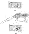
- the nozzle comprises a housing 1 with an inlet 2 to which a supply line for supplying a fluid is connected. (not shown).
- a discharge pipe 3 is inserted, at the front end of which an outlet 25 is located.
- the outlet 25 can, for example, be inserted into a filler neck 22, 26 of a vehicle (see Figures 5 and 7 ).
- a main channel 16 extends from the inlet 2 to the outlet 25, in which a main valve 5 is arranged to control the total volume flow.
- the main valve 5 comprises a main valve body 6 (see Figure 2 ), which can be moved against a main valve seat 27 to close the main valve 5.
- the valve body 6 is coupled to a switching lever 4 and to an automatic shut-off device 30 via a valve stem 15 in a basically known manner.
- the valve stem 15 has an outer sleeve 24, which holds the valve body 6 in the closed position (see Figures 1 and 2 ) with a large closing force against the valve seat 27.
- the valve stem 15 also comprises an inner piston 12 which is designed to be movable relative to the outer sleeve 24 and which is urged upstream by a return element 13 (see Figure 2 ).
- the valve body 6 is connected to the inner piston 12.
- the switching lever 4 When the switching lever 4 is operated by a user, the outer sleeve 24 of the valve stem 15 is moved downstream and thereby lifted off the valve body 6.
- the valve body 6 is now pressed into the closed position only by the restoring force of the restoring element 13 (see also Figure 4 ).
- the restoring force of the restoring element 13 is so small that the valve body 6 together with the inner piston 12 can be moved into the open position by a normal fluid pressure.
- the automatic shut-off device 30 is designed to move the main valve 5 into a closed position regardless of the position of the switching lever 4.
- the functioning of the automatic shut-off device is basically known (see for example EP 2 386 520 A1 ) and will not be explained in more detail here.
- the nozzle is designed to optionally deliver a first maximum volume flow or a second maximum volume flow.
- the nozzle comprises a throttle valve arranged in the outlet pipe, which is designed to optionally limit the fluid flow to the first or second maximum volume flow.
- the throttle valve is actuated by interaction with a ring magnet of a filler neck according to ISO 22241-4. By default, i.e. if there is no ring magnet, the nozzle is set to deliver the first maximum volume flow. If the outlet pipe 3 is inserted into a filler neck without a ring magnet, the first maximum volume flow can be delivered by operating the switch lever 4.
- the first maximum volume flow is 9 l/min in this case.
- the nozzle can deliver the second maximum volume flow, which is 20 l/min in this case.
- the functionality of the throttle valve is explained in conjunction with the Figures 9 to 11 explained in more detail.
- the functioning of the automatic shutdown device 30 requires that it be subjected to a vacuum.
- the vacuum is generated as described below.
- the main channel 16 merges downstream of the main valve 5 in the area 14 into a sub-channel 10 and into five parallel bridging channels 20a to 20e (see Figure 3 ).
- the partial channel 10 is delimited by a wall 31.
- the partial channel 10 has an opening 32 defined by the wall 31 and a section 33 tapering conically from the opening 32 in the direction of flow (see Figure 2 ). In the area of section 33 there is an inlet 8 of a vacuum line 9 into the partial channel 10. Due to the tapering section 33, the flow speed of the fluid in the partial channel 10 increases, so that the static pressure drops.
- the bridging channels 20a to 20e each have a means for prioritizing the fluid flow, which in the present case is designed as an overflow valve 21a to 21e, whereby the overflow valves 21d and 21e are not visible in the sectional view shown.
- the Figure 2 The overflow valve 21c shown in FIG. 1 is described. It comprises a shaft 19 and a closing body 17, which is tensioned upstream into a closed position by a return element 18. In the Figures 1 to 3 the main valve 5 is closed so that no fluid flows through the main channel 16. The closing body 17 of the overflow valve 21c is held in the closed position by the return element 18. The other overflow valves are also in the Figures 1 to 3 accordingly in their closed position.
- the return elements 18 of the overflow valves 21a to 21e have different return forces, so that different fluid pressures are required to open the overflow valves 21a to 21e. This will be explained below in connection with the Figures 5 to 8 explained in more detail.
- valve stem 15 By operating the control lever 4, the valve stem 15 is moved downstream so that the outer sleeve 24 of the valve stem 15 is released from the valve body 6 (see Figure 4 ). If no fluid is supplied to the inlet 2, the valve body 6 initially remains in the closed position, as already explained above, in which it is pressed against the valve seat 27 by the return element 13. This is in the Figure 4 illustrated.
- the valve body 6 Only when a fluid with a certain fluid pressure is supplied to the inlet 2, the valve body 6 gives way to the opening pressure and moves against the force of the return element 13 into an opening position. This is shown in the Figures 5 and 6 shown.
- the fluid can now enter from the inlet 2 into the area 14 in front of the partial channel 10 and the bridging channels 20a - 20e. Part of the fluid flows into the partial channel 10 and another part of the fluid in the direction of the overflow valves 21a to 21e. Since the overflow valves 21a to 21e are initially forced into the closed position by the return elements 18, a larger proportion of the fluid initially flows through the partial channel 10, so that a flow occurs there shortly after the main valve 5 opens and a vacuum is generated.
- a fluid pressure builds up on the upstream-facing front surfaces of the closing bodies 17 of the overflow valves 21a to 21e, which depends on the supply pressure of the fluid, the opening position of the main valve and the available flow cross-sections within the nozzle downstream of the overflow valves 21a to 21e.
- the nozzle according to the invention is shown after the outlet pipe has been inserted into a filler neck 22 of a vehicle and the main valve has been opened.
- the filler neck 22 is designed in accordance with ISO 22241-5 and does not have a ring magnet. Accordingly, the throttle valve located in the outlet pipe 3 is in the closed position and allows a maximum flow through the outlet pipe 3 of approximately 9 l/min.
- the restoring forces of the overflow valves are set in particular so that the resulting fluid flow through the partial channel 10 assumes an optimal value for vacuum generation.
- the overflow valves 21d and 21e which cannot be seen in this view, also have a greater restoring force than the overflow valve 21b and therefore remain closed.
- FIGS. 7 and 8 show the nozzle according to the invention after it has been inserted into a filler neck 26 according to ISO 22241-4 with ring magnet 23.
- the ring magnet 23 actuates the throttle valve in a manner explained in more detail below, so that the nozzle can now deliver a maximum volume flow of 20 l/min. Due to the increased maximum volume flow, there is a higher fluid pressure in the area 14 in front of the partial channel 10 and the bridging channels 20a-20e, so that all overflow valves 21a-21e open (see Figure 8). By opening all overflow valves, the volume flow flowing through the partial channel 10 can be increased compared to the volume flow in the
- Figures 5 and 6 shown state can be kept almost the same.
- the vacuum generated by the partial channel 10 is thus essentially constant, regardless of whether the first maximum volume flow of approximately 9 l/min or the second maximum volume flow of approximately 20 l/min is delivered with the dispensing valve. Even with other volume flows, which can be set in particular with the aid of the hand lever and an opening position of the main valve corresponding to the hand lever position, the overflow valves according to the invention lead to an equalization of the vacuum generated.
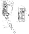
- Figure 9 shows a side sectional view through the outlet pipe 3 of the nozzle according to the invention.
- the sensor line 34 can be seen, which is in pneumatic connection with the automatic shut-off device 30.
- an accompanying pressure change leads to a triggering of the automatic shut-off device 30 and thus to a closing of the main valve 5.
- a safety valve 7 is also provided, which has a valve stem 35 and which closes downstream against a valve seat 36 (please refer Figure 10 ).
- the upstream end of the valve stem 35 is provided with a magnet 37.
- the outlet pipe 3 also has a sleeve 39 which can be displaced along its axial direction and which is moved by a spring 40 into the Figure 9
- a ring-shaped magnet 41 is arranged on the sleeve 39, which moves the valve stem 35 and the safety valve into the position shown in the Figure 9 shown closed position.
- the sensor line 34 has a sensor line valve 38 arranged at the outlet end with a valve stem 42, which closes against a valve seat with its outlet end.
- the valve stem 42 comprises an actuating magnet 43 at the opposite end, which holds the valve stem 42 in the closed position by interacting with the active magnet 41.
- the throttle valve 49 has a valve body 50, which is connected to a magnetic element 52 by means of a transmission rod 51.
- the magnetic element 52 is arranged in a cavity 53 within the valve stem 35 of the safety valve 7 and is displaceable relative to the valve stem 35 in the axial direction of the outlet pipe 3.
- the transmission rod 51 is also displaceable relative to the valve stem 35 and passes through a through opening located in an upstream-facing rear wall of the valve stem 35.
- the magnetic element 52 and the transmission rod 51 together form an actuating device for the throttle valve 49.
- the valve body 50 In the Figure 9 In the state shown, the valve body 50 is in a closed position in which it rests downstream against a valve seat 54 of the throttle valve 49. The valve body 50 is pushed downstream relative to the valve stem 35 by a return element 55 and is thereby clamped into the valve seat 54.
- the functioning of the actuating device 51, 52 and the setting of the throttle valve 49 to the second maximum volume flow is carried out in conjunction with the Figures 10 and 11 explained.
- the Figure 10 shows the outlet pipe 3 after it has been inserted into a filler neck 22 of a vehicle tank.
- the main valve 5 was moved into an open position by actuating the shift lever 4.
- the filler neck 22 in this case is the filler neck of a urea tank of a passenger car according to ISO 22241-5 without a ring magnet.
- the filler neck 22 is in a basically known manner (see EP 3 369 700 A1 ) is designed to move the sleeve 39 upstream of the outlet pipe 3 relative to the sleeve 39 when inserting the outlet pipe 3.
- Figure 9 shown blocking position into an open position.
- the associated magnet 41 also moves upstream relative to the outlet pipe 3, whereby it is guided by magnetic Interaction takes along the magnet 37 fixed to the valve stem 35 and the actuating magnet 43 fixed to the valve stem 42 and thus opens the sensor line valve 38 and the safety valve 7.
- the magnetic element 52 is sufficiently far away from the active magnet 41 so that it is not influenced by the displacement of the active magnet 41 or only in a negligible way. Since the magnetic element 52, the transmission rod 51 and the valve body 50 connected to it are movable relative to the valve stem 35 and are pushed into the closed position by the return element 55, the valve body 50 remains in the closed position. In the sectional view of the Figures 9 to 11 not visible through holes through which a certain volume flow can pass through the outlet pipe 3 even when the valve body 50 is in the closed position. This certain volume flow is at most as large as the first maximum volume flow of the throttle valve, which in this case is 9 l/min.
- the volume flow passing through the opening of the main valve 5 is therefore limited by the closed throttle valve 49 to the first maximum volume flow of the nozzle valve.
- through holes in the valve seat 54 through holes can also be provided in the valve body 50 in an alternative embodiment.
- the Figure 11 shows the outlet pipe after it has been inserted into a filler neck 26, which, in contrast to the filler neck 22 of the Figure 10 is the filler neck of a urea tank of a passenger car according to ISO 22241-4 with ring magnet 23.
- the main valve 5 is in an open position.
- the sleeve 39 When inserting the outlet pipe, the sleeve 39, as already described in connection with the Figure 10 described, is displaced relative to the outlet pipe 3 through the filler neck 26, so that both the sensor line valve 38 and the safety valve 7 are opened by the interaction between the active magnet 41 and the magnets 37 and 43.
- the ring magnet 23 and the magnetic element 52 are arranged in such a way that when the outlet pipe 3 is inserted into the filler neck 26, poles of the same name initially face each other and a repulsive force is thus exerted on the magnetic element 52.
- the magnetic element 52 is designed in such a way that the magnetic force exceeds the opposing restoring force of the restoring element 55. The repulsive force therefore leads to a displacement of the magnetic element 52 in an upstream direction relative to the outlet pipe 3. Due to the connection of the magnetic element 52 to the valve body 50 formed by the transmission rod 51, the valve body 50 is moved into an open position against the restoring force of the restoring element 55. The movement of the valve body 50 is limited upstream by a stop 56.
- the throttle valve 49 In the open position of the throttle valve 49, at a given fluid pressure at the inlet of the nozzle, a larger volume flow can pass through the outlet pipe than in the Figure 10 shown closed position.
- the throttle valve 49 in the state shown is designed, when the main valve 5 is sufficiently opened, to allow the second maximum volume flow through the outlet pipe 3, which in the present case is 20 l/min.
- the magnetic force acting between the ring magnet 23 and the magnetic element 52 is so large that the valve body 50 is held in the open position against the fluid pressure and against the restoring force of the restoring element 55.
Landscapes
- Engineering & Computer Science (AREA)
- Mechanical Engineering (AREA)
- Lift Valve (AREA)
- Basic Packing Technique (AREA)
- Valve Housings (AREA)
- Filling Of Jars Or Cans And Processes For Cleaning And Sealing Jars (AREA)
Applications Claiming Priority (3)
| Application Number | Priority Date | Filing Date | Title |
|---|---|---|---|
| EP20198850 | 2020-09-29 | ||
| EP21786103.8A EP4222105B1 (fr) | 2020-09-29 | 2021-09-22 | Pistolet de soutirage à fermeture automatique |
| PCT/EP2021/076094 WO2022069319A1 (fr) | 2020-09-29 | 2021-09-22 | Buse de remplissage à fermeture automatique |
Related Parent Applications (2)
| Application Number | Title | Priority Date | Filing Date |
|---|---|---|---|
| EP21786103.8A Division EP4222105B1 (fr) | 2020-09-29 | 2021-09-22 | Pistolet de soutirage à fermeture automatique |
| EP21786103.8A Division-Into EP4222105B1 (fr) | 2020-09-29 | 2021-09-22 | Pistolet de soutirage à fermeture automatique |
Publications (2)
| Publication Number | Publication Date |
|---|---|
| EP4385942A2 true EP4385942A2 (fr) | 2024-06-19 |
| EP4385942A3 EP4385942A3 (fr) | 2024-08-28 |
Family
ID=72670505
Family Applications (2)
| Application Number | Title | Priority Date | Filing Date |
|---|---|---|---|
| EP24173233.8A Pending EP4385942A3 (fr) | 2020-09-29 | 2021-09-22 | Pistolet de soutirage |
| EP21786103.8A Active EP4222105B1 (fr) | 2020-09-29 | 2021-09-22 | Pistolet de soutirage à fermeture automatique |
Family Applications After (1)
| Application Number | Title | Priority Date | Filing Date |
|---|---|---|---|
| EP21786103.8A Active EP4222105B1 (fr) | 2020-09-29 | 2021-09-22 | Pistolet de soutirage à fermeture automatique |
Country Status (7)
| Country | Link |
|---|---|
| US (1) | US20250320108A1 (fr) |
| EP (2) | EP4385942A3 (fr) |
| CN (1) | CN116234767A (fr) |
| AU (1) | AU2021352963A1 (fr) |
| ES (1) | ES2985380T3 (fr) |
| PL (1) | PL4222105T3 (fr) |
| WO (1) | WO2022069319A1 (fr) |
Citations (3)
| Publication number | Priority date | Publication date | Assignee | Title |
|---|---|---|---|---|
| EP2386520A1 (fr) | 2010-05-14 | 2011-11-16 | Elaflex Hiby Tanktechnik GmbH & Co. | Buse de distribution |
| EP2733113A1 (fr) | 2012-11-14 | 2014-05-21 | Elaflex Hiby Tanktechnik GmbH & Co. | Buse de distribution avec soupape de sécurité |
| EP3369700A1 (fr) | 2017-03-03 | 2018-09-05 | Elaflex Hiby Tanktechnik GmbH & Co. | Buse de distribution pour deux debits maximales |
Family Cites Families (14)
| Publication number | Priority date | Publication date | Assignee | Title |
|---|---|---|---|---|
| US2320033A (en) * | 1939-04-24 | 1943-05-25 | American Machine & Metals | Filling nozzle with automatic shutoff |
| GB559643A (en) * | 1942-01-15 | 1944-02-29 | Ernst Giger | Device for automatically closing the supply pipe for tanks of all kinds such as the supply pipe to the tanks of aircraft and power vehicles |
| US3370623A (en) * | 1965-05-21 | 1968-02-27 | American Nat Valve Corp | Fluid dispensing device |
| GB1562494A (en) * | 1975-09-12 | 1980-03-12 | Emco Wheaton | Nozzles |
| US4133355A (en) * | 1976-06-07 | 1979-01-09 | Texaco Inc. | Sealable dispensing nozzle with automatic shut-off |
| US4951722A (en) * | 1987-03-04 | 1990-08-28 | Nitzberg Leonard R | Fuel dispensing nozzle having a flow rate limiter |
| US5341855A (en) * | 1992-06-03 | 1994-08-30 | Rabinovich Joshua E | Vapor recovery nozzle |
| US5297594A (en) * | 1992-06-03 | 1994-03-29 | Rabinovich Joshua E | Vapor recovery nozzle |
| US5327949A (en) * | 1992-10-19 | 1994-07-12 | Emco Wheaton, Inc. | Fuel dispensing nozzle |
| US5645115A (en) * | 1994-09-06 | 1997-07-08 | Dover Corporation | Dispensing nozzles |
| NL1006898C2 (nl) * | 1997-09-01 | 1999-03-02 | Opw Fueling Components Europ B | Vulpistool met eindklep en venturi in de van het afgifte-uiteinde voorziene helft van de spuitmond. |
| US7134580B2 (en) * | 2003-10-10 | 2006-11-14 | Delaware Capital Formation, Inc. | Spout assembly for dispensing liquid from a nozzle |
| CN205118338U (zh) * | 2015-10-20 | 2016-03-30 | 郑州永邦环保科技有限公司 | 油气回收系统用真空流量控制及气液比例调节阀 |
| EP3647260A1 (fr) * | 2018-10-30 | 2020-05-06 | Elaflex Hiby Tanktechnik GmbH & Co. | Dispositif d'aller et de retour de fluides |
-
2021
- 2021-09-22 CN CN202180066607.8A patent/CN116234767A/zh active Pending
- 2021-09-22 EP EP24173233.8A patent/EP4385942A3/fr active Pending
- 2021-09-22 AU AU2021352963A patent/AU2021352963A1/en active Pending
- 2021-09-22 ES ES21786103T patent/ES2985380T3/es active Active
- 2021-09-22 US US18/026,998 patent/US20250320108A1/en active Pending
- 2021-09-22 PL PL21786103.8T patent/PL4222105T3/pl unknown
- 2021-09-22 WO PCT/EP2021/076094 patent/WO2022069319A1/fr not_active Ceased
- 2021-09-22 EP EP21786103.8A patent/EP4222105B1/fr active Active
Patent Citations (3)
| Publication number | Priority date | Publication date | Assignee | Title |
|---|---|---|---|---|
| EP2386520A1 (fr) | 2010-05-14 | 2011-11-16 | Elaflex Hiby Tanktechnik GmbH & Co. | Buse de distribution |
| EP2733113A1 (fr) | 2012-11-14 | 2014-05-21 | Elaflex Hiby Tanktechnik GmbH & Co. | Buse de distribution avec soupape de sécurité |
| EP3369700A1 (fr) | 2017-03-03 | 2018-09-05 | Elaflex Hiby Tanktechnik GmbH & Co. | Buse de distribution pour deux debits maximales |
Also Published As
| Publication number | Publication date |
|---|---|
| US20250320108A1 (en) | 2025-10-16 |
| AU2021352963A1 (en) | 2023-05-04 |
| AU2021352963A9 (en) | 2024-06-27 |
| PL4222105T3 (pl) | 2024-09-16 |
| EP4385942A3 (fr) | 2024-08-28 |
| EP4222105C0 (fr) | 2024-06-12 |
| WO2022069319A1 (fr) | 2022-04-07 |
| CA3194132A1 (fr) | 2022-04-07 |
| EP4222105A1 (fr) | 2023-08-09 |
| ES2985380T3 (es) | 2024-11-05 |
| CN116234767A (zh) | 2023-06-06 |
| EP4222105B1 (fr) | 2024-06-12 |
Similar Documents
| Publication | Publication Date | Title |
|---|---|---|
| DE602005000662T2 (de) | Einspritzventil einer Brennkraftmaschine | |
| DE2511662C3 (de) | Bewässerungsvorrichtung | |
| WO2011000907A1 (fr) | Presse hydraulique | |
| DE2012527A1 (de) | Ventil zur Steuerung von unter hohem Druck stehendem, Dampfturbinen zuzuführendem Dampf | |
| DE10001099A1 (de) | Steuerventil für einen Injektor eines Kraftstoffeinspritzsystems für Brennkraftmaschinen mit Druckerhöhung im Steuerraum | |
| EP2592519A1 (fr) | Dispositif de réglage de pression et procédé de fonctionnement d'un dispositif de réglage de pression | |
| EP2031237B1 (fr) | Injecteur destiné à l'injection de carburant | |
| EP2470771A1 (fr) | Injecteur de carburant | |
| EP2428485B1 (fr) | Buse de distribution | |
| EP0659947A2 (fr) | Dispositif de commande pour une vanne d'obturation actionnée par dépression | |
| EP4222105B1 (fr) | Pistolet de soutirage à fermeture automatique | |
| EP4172486A1 (fr) | Limiteur de débit d'un système d'injection de carburant et système d'injection de carburant comprenant un limiteur de débit | |
| EP1952011B1 (fr) | Dispositif d'injection de carburant pour moteur a combustion interne a injection directe de carburant | |
| EP3446006A1 (fr) | Soupape de fermeture et d'ouverture d'un système de conduites | |
| WO2024240568A1 (fr) | Ensemble soupape de réservoir et procédé de remplissage d'un accumulateur de gaz sous pression | |
| EP3974374B1 (fr) | Buse de distribution avec interrupteur entre deux débits maximaux | |
| EP4514740B1 (fr) | Soupape de soutirage | |
| DE2905199B2 (de) | Vorrichtung zur Regelung des Unterdruckes in einem Unterdruckleitungssystem, insbesondere für Melkanlagen | |
| EP4065508B1 (fr) | Pistolet de distribution doté d'un dispositif de protection contre les fuites | |
| EP4010580A1 (fr) | Limiteur de débit d'un système d'injection de carburant et système d'injection de carburant | |
| EP3978425B1 (fr) | Soupape de soutirage pourvue de soupape à gaz à commutation séparvée et agencement comprenant une telle soupape de soutirage et installation de recirculation des gaz | |
| AT511731B1 (de) | Kavitationsoptimierte drosselbohrungen | |
| EP4487053B1 (fr) | Soupape d'arrêt et système de réservoir d'hydrogène comprenant une soupape d'arrêt | |
| DE29518733U1 (de) | Druckhalteventil für Kraftstoffanlagen | |
| WO2020089161A1 (fr) | Dispositif de distribution et de retour de fluides |
Legal Events
| Date | Code | Title | Description |
|---|---|---|---|
| PUAI | Public reference made under article 153(3) epc to a published international application that has entered the european phase |
Free format text: ORIGINAL CODE: 0009012 |
|
| STAA | Information on the status of an ep patent application or granted ep patent |
Free format text: STATUS: THE APPLICATION HAS BEEN PUBLISHED |
|
| AC | Divisional application: reference to earlier application |
Ref document number: 4222105 Country of ref document: EP Kind code of ref document: P |
|
| AK | Designated contracting states |
Kind code of ref document: A2 Designated state(s): AL AT BE BG CH CY CZ DE DK EE ES FI FR GB GR HR HU IE IS IT LI LT LU LV MC MK MT NL NO PL PT RO RS SE SI SK SM TR |
|
| REG | Reference to a national code |
Ref country code: DE Ref legal event code: R079 Free format text: PREVIOUS MAIN CLASS: B67D0007520000 Ipc: B67D0007480000 |
|
| PUAL | Search report despatched |
Free format text: ORIGINAL CODE: 0009013 |
|
| AK | Designated contracting states |
Kind code of ref document: A3 Designated state(s): AL AT BE BG CH CY CZ DE DK EE ES FI FR GB GR HR HU IE IS IT LI LT LU LV MC MK MT NL NO PL PT RO RS SE SI SK SM TR |
|
| RIC1 | Information provided on ipc code assigned before grant |
Ipc: B67D 7/52 20100101ALI20240722BHEP Ipc: B67D 7/02 20100101ALI20240722BHEP Ipc: B67D 7/48 20100101AFI20240722BHEP |
|
| STAA | Information on the status of an ep patent application or granted ep patent |
Free format text: STATUS: REQUEST FOR EXAMINATION WAS MADE |
|
| 17P | Request for examination filed |
Effective date: 20250227 |