EP4386119A2 - Spinnfadenziehvorrichtung - Google Patents
Spinnfadenziehvorrichtung Download PDFInfo
- Publication number
- EP4386119A2 EP4386119A2 EP23210108.9A EP23210108A EP4386119A2 EP 4386119 A2 EP4386119 A2 EP 4386119A2 EP 23210108 A EP23210108 A EP 23210108A EP 4386119 A2 EP4386119 A2 EP 4386119A2
- Authority
- EP
- European Patent Office
- Prior art keywords
- yarn
- upstream
- heating roller
- downstream
- roller
- Prior art date
- Legal status (The legal status is an assumption and is not a legal conclusion. Google has not performed a legal analysis and makes no representation as to the accuracy of the status listed.)
- Pending
Links
- 238000010438 heat treatment Methods 0.000 claims abstract description 534
- 238000009413 insulation Methods 0.000 claims abstract description 124
- 238000004804 winding Methods 0.000 claims abstract description 15
- 238000011144 upstream manufacturing Methods 0.000 claims description 174
- 230000001105 regulatory effect Effects 0.000 claims description 28
- 239000004677 Nylon Substances 0.000 claims description 14
- 229920001778 nylon Polymers 0.000 claims description 14
- 238000009987 spinning Methods 0.000 claims description 13
- 230000001154 acute effect Effects 0.000 claims description 10
- 238000005192 partition Methods 0.000 claims description 7
- 238000012986 modification Methods 0.000 description 35
- 230000004048 modification Effects 0.000 description 35
- 230000000694 effects Effects 0.000 description 34
- 230000000052 comparative effect Effects 0.000 description 29
- 239000012530 fluid Substances 0.000 description 18
- 238000004088 simulation Methods 0.000 description 8
- 230000003750 conditioning effect Effects 0.000 description 4
- 238000011156 evaluation Methods 0.000 description 4
- 238000010586 diagram Methods 0.000 description 3
- 238000005452 bending Methods 0.000 description 2
- 238000000034 method Methods 0.000 description 2
- 239000003595 mist Substances 0.000 description 2
- 230000002265 prevention Effects 0.000 description 2
- 229920002292 Nylon 6 Polymers 0.000 description 1
- 229920002302 Nylon 6,6 Polymers 0.000 description 1
- 230000001174 ascending effect Effects 0.000 description 1
- 230000000903 blocking effect Effects 0.000 description 1
- 230000005484 gravity Effects 0.000 description 1
- 229920000728 polyester Polymers 0.000 description 1
- 229920000642 polymer Polymers 0.000 description 1
Images






Classifications
-
- D—TEXTILES; PAPER
- D02—YARNS; MECHANICAL FINISHING OF YARNS OR ROPES; WARPING OR BEAMING
- D02J—FINISHING OR DRESSING OF FILAMENTS, YARNS, THREADS, CORDS, ROPES OR THE LIKE
- D02J1/00—Modifying the structure or properties resulting from a particular structure; Modifying, retaining, or restoring the physical form or cross-sectional shape, e.g. by use of dies or squeeze rollers
- D02J1/22—Stretching or tensioning, shrinking or relaxing, e.g. by use of overfeed and underfeed apparatus, or preventing stretch
-
- D—TEXTILES; PAPER
- D01—NATURAL OR MAN-MADE THREADS OR FIBRES; SPINNING
- D01D—MECHANICAL METHODS OR APPARATUS IN THE MANUFACTURE OF ARTIFICIAL FILAMENTS, THREADS, FIBRES, BRISTLES OR RIBBONS
- D01D5/00—Formation of filaments, threads, or the like
- D01D5/12—Stretch-spinning methods
- D01D5/16—Stretch-spinning methods using rollers, or like mechanical devices, e.g. snubbing pins
-
- D—TEXTILES; PAPER
- D01—NATURAL OR MAN-MADE THREADS OR FIBRES; SPINNING
- D01D—MECHANICAL METHODS OR APPARATUS IN THE MANUFACTURE OF ARTIFICIAL FILAMENTS, THREADS, FIBRES, BRISTLES OR RIBBONS
- D01D10/00—Physical treatment of artificial filaments or the like during manufacture, i.e. during a continuous production process before the filaments have been collected
-
- D—TEXTILES; PAPER
- D01—NATURAL OR MAN-MADE THREADS OR FIBRES; SPINNING
- D01D—MECHANICAL METHODS OR APPARATUS IN THE MANUFACTURE OF ARTIFICIAL FILAMENTS, THREADS, FIBRES, BRISTLES OR RIBBONS
- D01D10/00—Physical treatment of artificial filaments or the like during manufacture, i.e. during a continuous production process before the filaments have been collected
- D01D10/02—Heat treatment
-
- D—TEXTILES; PAPER
- D01—NATURAL OR MAN-MADE THREADS OR FIBRES; SPINNING
- D01D—MECHANICAL METHODS OR APPARATUS IN THE MANUFACTURE OF ARTIFICIAL FILAMENTS, THREADS, FIBRES, BRISTLES OR RIBBONS
- D01D13/00—Complete machines for producing artificial threads
- D01D13/02—Elements of machines in combination
-
- D—TEXTILES; PAPER
- D02—YARNS; MECHANICAL FINISHING OF YARNS OR ROPES; WARPING OR BEAMING
- D02J—FINISHING OR DRESSING OF FILAMENTS, YARNS, THREADS, CORDS, ROPES OR THE LIKE
- D02J13/00—Heating or cooling the yarn, thread, cord, rope, or the like, not specific to any one of the processes provided for in this subclass
- D02J13/005—Heating or cooling the yarn, thread, cord, rope, or the like, not specific to any one of the processes provided for in this subclass by contact with at least one rotating roll
Definitions
- the present invention relates to a spun yarn drawing apparatus.
- Patent Literature 1 Japanese Laid-Open Patent Publication No. 2019-131898 discloses a spun yarn drawing apparatus configured to draw a polyester yarn spun out from a spinning apparatus.
- the spun yarn drawing apparatus includes plural godet rollers onto which the running yarn is wound and a thermal insulation box housing the godet rollers.
- the godet rollers include plural preheating rollers configured to preheat the yarn and plural conditioning rollers which are provided downstream of the preheating rollers in a yarn running direction and whose surface temperatures are higher than those of the preheating rollers. The yarn is drawn between the preheating rollers and the conditioning rollers in such a spun yarn drawing apparatus.
- a shielding member is provided in order to prevent an accompanied flow from escaping from the thermal insulation box.
- the accompanied flow is generated as the conditioning rollers rotate. This increases a heat retaining effect, and suppresses the increase in power consumption of a heater configured to heat the godet rollers.
- a known spun yarn drawing apparatus is configured to draw a nylon yarn.
- the known spun yarn drawing apparatus for nylon yarns includes known Nelson-type rollers.
- a typical spun yarn drawing apparatus for nylon yarns is structured so that the Nelson-type rollers include a non-heating roller which is not heated and a heating roller which is provided for thermal setting on the downstream side of the non-heating roller in the yarn running direction. The yarn is drawn between the non-heating roller and the heating roller in such a spun yarn drawing apparatus.
- a heating effect of a Nelson-type roller is increased by winding the yarn onto the Nelson-type roller several times while changing the position of the yarn in the axial direction of the Nelson-type roller. Therefore, a force in the axial direction is applied to the yarn wound onto the Nelson-type roller, and yarn swing easily occurs.
- the spun yarn drawing apparatus which is able to draw the nylon yarn is also required to suppress the power consumption of a heater.
- An object of the present invention is to suppress yarn swing and the increase in power consumption in a spun yarn drawing apparatus.
- a spun yarn drawing apparatus is configured to draw a running yarn spun out from a spinning apparatus.
- the spun yarn drawing apparatus comprises: three or more heating rollers onto which the yarn is wound at a winding angle of less than 360 degrees and which are configured to heat and send the yarn to a downstream side in a yarn running direction; and a thermal insulation box housing the three or more heating rollers, the three or more heating rollers include: a most upstream heating roller provided on the most upstream side in the yarn running direction among the three or more heating rollers; a most downstream heating roller provided on the most downstream side in the yarn running direction among the three or more heating rollers; and one or more intermediate heating rollers which are provided downstream of the most upstream heating roller and upstream of the most downstream heating roller in the yarn running direction, and the thermal insulation box includes: one or more circulators which are respectively provided around one or more predetermined upstream heating rollers among two or more upstream heating rollers including the most upstream heating roller and the one or more intermediate heating rollers and each of which is configured to
- the rotation of the each of the one or more predetermined upstream heating rollers generates the roller accompanied flow which is an accompanied flow
- the one or more predetermined upstream heating rollers include the one or more intermediate heating rollers
- the one or more circulators are provided to correspond to all of the one or more intermediate heating rollers.
- the yarn is sufficiently heated without using a Nelson roller in which yarn swing is likely to occur.
- the yarn swing is therefore suppressed as compared to a case where the Nelson roller is provided.
- the one or more circulators cause roller accompanied flows to circulate around the one or more predetermined upstream heating rollers so that gas heated by the one or more predetermined upstream heating rollers is suppressed from escaping from the thermal insulation box through an exit of the yarn.
- This increases a heat retaining effect of the thermal insulation box.
- the roller accompanied flows are circulated by the one or more circulators so that gas of the roller accompanied flows is kept heated by the one or more predetermined upstream heating rollers. This increases a heat retaining effect around each predetermined upstream heating roller, and thus increases that of each predetermined upstream heating roller itself. Therefore, the increase in power consumption is suppressed in the spun yarn drawing apparatus while the yarn swing is suppressed.
- an accompanied flow (hereinafter, this will be referred to as the yarn accompanied flow) generated by running of the yarn also flows into the thermal insulation box.
- the most upstream heating roller is easily cooled by such cool air flowing into the thermal insulation box from outside. Because the one or more intermediate heating rollers are relatively close to the most upstream heating roller, heat from the one or more intermediate heating rollers is transmitted to the most upstream heating roller side by increasing the heat retaining effect of each intermediate heating roller. It is therefore possible to increase the heat retaining effect of the most upstream heating roller.
- the heat retaining effect of the thermal insulation box is effectively increased.
- the spun yarn drawing apparatus of the first aspect is arranged such that one of the one or more circulators is a predetermined circulator, in a cross section taken along a line orthogonal to a rotational axis direction of a predetermined heating roller which is one of the one or more predetermined upstream heating rollers and which is provided to correspond to the predetermined circulator, a part of an outer circumferential surface of the predetermined heating roller is a contact surface with which the yarn is in contact, the most upstream part of the contact surface in the yarn running direction is a contact start point, the most downstream part of the contact surface in the yarn running direction is a contact end point, another part of the outer circumferential surface is a contactless surface with which the yarn is not in contact, an upstream yarn path is provided upstream of the contact start point in the yarn running direction, a downstream yarn path is provided downstream of the contact end point in the yarn running direction, and the predetermined circulator includes an accompanied flow collecting surface which is provided to face the contactless surface, which is
- the accompanied flow collecting surface makes it possible to suppress a roller accompanied flow from flowing radially outward of the outer circumferential surface because of a centrifugal force. It is therefore possible to effectively circulate the roller accompanied flow with a simple structure.
- the spun yarn drawing apparatus of the second aspect is arranged such that, in the cross section, a first virtual line segment connects the first point to the second point, a second virtual line segment connects the center of the predetermined heating roller in a radial direction of the predetermined heating roller to the first point, and an angle between the first virtual line segment and the second virtual line segment is an acute angle.
- a roller accompanied flow flowing in the vicinity of the first point is guided by the accompanied flow collecting surface so as to flow inward in the radial direction and in the circumferential direction. This allows the roller accompanied flow to smoothly flow along the accompanied flow collecting surface.
- the spun yarn drawing apparatus of the second or third aspect is arranged such that, in the cross section, the shortest distance between the outer circumferential surface and the accompanied flow collecting surface is 11 mm or more and 88 mm or less.
- the shortest distance between the outer circumferential surface and the accompanied flow collecting surface is 11 mm or more and 88 mm or less. It is therefore possible to suppress the above-described problems.
- a spun yarn drawing apparatus is configured to draw a running yarn spun out from a spinning apparatus.
- the spun yarn drawing apparatus comprises: three or more heating rollers onto which the yarn is wound at a winding angle of less than 360 degrees and which are configured to heat and send the yarn to a downstream side in a yarn running direction; and a thermal insulation box housing the three or more heating rollers, the three or more heating rollers include: a most upstream heating roller provided on the most upstream side in the yarn running direction among the three or more heating rollers; a most downstream heating roller provided on the most downstream side in the yarn running direction among the three or more heating rollers; and one or more intermediate heating rollers which are provided downstream of the most upstream heating roller and upstream of the most downstream heating roller in the yarn running direction, the thermal insulation box includes: one or more circulators which are respectively provided around one or more predetermined upstream heating rollers among two or more upstream heating rollers including the most upstream heating roller and the one or more intermediate heating rollers and each of which is configured to cause
- one of the one or more circulators is a predetermined circulator, in a cross section taken along a line orthogonal to a rotational axis direction of a predetermined heating roller which is one of the one or more predetermined upstream heating rollers and which is provided to correspond to the predetermined circulator, a part of an outer circumferential surface of the predetermined heating roller is a contact surface with which the yarn is in contact, the most upstream part of the contact surface in the yarn running direction is a contact start point, the most downstream part of the contact surface in the yarn running direction is a contact end point, another part of the outer circumferential surface is a contactless surface with which the yarn is not in contact, an upstream yarn path is provided upstream of the contact start point in the yarn running direction, a downstream yarn path is provided downstream of the contact end point in the yarn running direction, the predetermined circulator includes an accompanied flow collecting surface which is provided
- the shortest distance between the outer circumferential surface and the accompanied flow collecting surface is 11 mm or more and 88 mm or less. It is therefore possible to suppress the above-described problems.
- the spun yarn drawing apparatus of the fifth aspect is arranged such that, in the cross section, a first virtual line segment connects the first point to the second point, a second virtual line segment connects the center of the predetermined heating roller in a radial direction of the predetermined heating roller to the first point, and an angle between the first virtual line segment and the second virtual line segment is an acute angle.
- a roller accompanied flow flowing in the vicinity of the first point is guided by the accompanied flow collecting surface so as to flow inward in the radial direction and in the circumferential direction. This allows the roller accompanied flow to smoothly flow along the accompanied flow collecting surface.
- an accompanied flow (hereinafter, this will be referred to as the yarn accompanied flow) generated by running of the yarn also flows into the thermal insulation box.
- the most upstream heating roller is easily cooled by such cool air flowing into the thermal insulation box from outside. Because the one or more intermediate heating rollers are relatively close to the most upstream heating roller, heat from the one or more intermediate heating rollers is transmitted to the most upstream heating roller side by increasing the heat retaining effect of each intermediate heating roller. It is therefore possible to increase the heat retaining effect of the most upstream heating roller.
- a spun yarn drawing apparatus is configured to draw a running yarn spun out from a spinning apparatus.
- the spun yarn drawing apparatus comprises: three or more heating rollers onto which the yarn is wound at a winding angle of less than 360 degrees and which are configured to heat and send the yarn to a downstream side in a yarn running direction; and a thermal insulation box housing the three or more heating rollers, the three or more heating rollers include: a most upstream heating roller provided on the most upstream side in the yarn running direction among the three or more heating rollers; a most downstream heating roller provided on the most downstream side in the yarn running direction among the three or more heating rollers; and one or more intermediate heating rollers which are provided downstream of the most upstream heating roller and upstream of the most downstream heating roller in the yarn running direction, the thermal insulation box includes: one or more circulators which are respectively provided around one or more predetermined upstream heating rollers among two or more upstream heating rollers including the most upstream heating roller and the one or more intermediate heating rollers and each of which is configured to cause
- one of the one or more circulators is a predetermined circulator, in a cross section taken along a line orthogonal to a rotational axis direction of a predetermined heating roller which is one of the one or more predetermined upstream heating rollers and which is provided to correspond to the predetermined circulator, a part of an outer circumferential surface of the predetermined heating roller is a contact surface with which the yarn is in contact, the most upstream part of the contact surface in the yarn running direction is a contact start point, the most downstream part of the contact surface in the yarn running direction is a contact end point, another part of the outer circumferential surface is a contactless surface with which the yarn is not in contact, an upstream yarn path is provided upstream of the contact start point in the yarn running direction, a downstream yarn path is provided downstream of the contact end point in the yarn running direction, the predetermined circulator includes an accompanied flow collecting surface which is provided
- a roller accompanied flow flowing in the vicinity of the first point is guided by the accompanied flow collecting surface so as to flow inward in the radial direction and in the circumferential direction. This allows the roller accompanied flow to smoothly flow along the accompanied flow collecting surface.
- the spun yarn drawing apparatus of the eighth aspect is arranged such that the one or more predetermined upstream heating rollers include the one or more intermediate heating rollers.
- an accompanied flow (hereinafter, this will be referred to as the yarn accompanied flow) generated by running of the yarn also flows into the thermal insulation box.
- the most upstream heating roller is easily cooled by such cool air flowing into the thermal insulation box from outside. Because the one or more intermediate heating rollers are relatively close to the most upstream heating roller, heat from the one or more intermediate heating rollers is transmitted to the most upstream heating roller side by increasing the heat retaining effect of each intermediate heating roller. It is therefore possible to increase the heat retaining effect of the most upstream heating roller.
- the spun yarn drawing apparatus of any one of the second to ninth aspects is arranged such that, in the cross section, a virtual upstream straight line contains the contact start point and partially overlaps the upstream yarn path, a virtual downstream straight line contains the contact end point and partially overlaps the downstream yarn path, the virtual upstream straight line is line-symmetric with the virtual downstream straight line about a predetermined symmetry axis, and the first point is provided between the symmetry axis and the virtual downstream straight line.
- the first point is provided in the vicinity of the contact end point.
- the spun yarn drawing apparatus of any one of the second to tenth aspects is arranged such that, in the cross section, the accompanied flow collecting surface forms a line segment connecting the first point to the second point, is curved and protrudes outward of the line segment in the radial direction of the predetermined heating roller, or is bent and protrudes outward of the line segment in the radial direction of the predetermined heating roller to form an obtuse angle.
- a roller accompanied flow smoothly flows along the accompanied flow collecting surface.
- the spun yarn drawing apparatus of the eleventh aspect is arranged such that the accompanied flow collecting surface forms the line segment in the cross section.
- the accompanied flow collecting surface is flat.
- the accompanied flow collecting surface is therefore formed by a simple process as compared to a case where the accompanied flow collecting surface is curved or bent.
- the spun yarn drawing apparatus of any one of the second to twelfth aspects is arranged such that the predetermined circulator includes an accompanied flow regulating surface provided to enclose the contact surface in the circumferential direction.
- the accompanied flow regulating surface makes it possible to suppress a roller accompanied flow from flowing radially outward of the outer circumferential surface because of a centrifugal force.
- the spun yarn drawing apparatus of the thirteenth aspect is arranged such that a virtual half-line whose endpoint is the first point and which passes the second point intersects with the accompanied flow regulating surface in the cross section.
- a roller accompanied flow guided by the accompanied flow collecting surface is supplied toward the accompanied flow regulating surface. It is therefore possible to further effectively circulate the roller accompanied flow.
- the spun yarn drawing apparatus of any one of the second to fourteenth aspects is arranged such that, when an intersection between (i) the virtual half-line whose endpoint is the first point and which passes the second point and (ii) a yarn path of the yarn running toward the contact start point is a third point in the cross section, a third virtual line segment connects the second point to the third point, a fourth virtual line segment connects the third point to the contact start point, and an angle between the third virtual line segment and the fourth virtual line segment is an obtuse angle in the cross section.
- a roller accompanied flow guided by the accompanied flow collecting surface is prevented from flowing in a direction opposite to a traveling direction of the yarn. It is therefore possible to suppress the yarn swing.
- the spun yarn drawing apparatus of any one of the first to fifteenth aspects is arranged such that the one or more circulators are configured to cause roller accompanied flows to circulate around the one or more predetermined upstream heating rollers respectively so that a layer flow along the yarn running direction is generated around the each of the one or more predetermined upstream heating rollers.
- a roller accompanied flow circulates around each predetermined upstream heating roller so as to cause a stable layer flow. Therefore, even when a flow rate of circulating gas is large, the yarn swing is suppressed.
- the spun yarn drawing apparatus of any one of the first to sixteenth aspects is arranged such that the thermal insulation box includes: a partition portion provided between (i) a downstream heating roller which is one of the most downstream heating roller and the one or more intermediate heating rollers and (ii) the most upstream heating roller; and a returning path causing a downstream space provided on the downstream heating roller side of the partition portion to communicate with an upstream space provided on the most upstream heating roller side of the partition portion.
- the most upstream heating roller is easily cooled by cool air flowing in from an entrance of the yarn, which is formed at the thermal insulation box. According to this aspect, high-temperature air in the downstream space is supplied to the upstream space through the returning path. It is therefore possible to effectively increase the heat retaining effect of the most upstream heating roller.
- the spun yarn drawing apparatus of any one of the first to seventeenth aspects is arranged such that the one or more predetermined upstream heating rollers include the most upstream heating roller.
- the heat retaining effect of the most upstream heating roller is increased. It is therefore possible to effectively reduce the power consumption.
- the spun yarn drawing apparatus of any one of the first to eighteenth aspects is arranged such that the thermal insulation box includes: an exit of the yarn; and a shielding portion which extends toward a most downstream contact surface and which is configured to block a yarn accompanied flow generated by the yarn running toward the exit, a part of an outer circumferential surface of the most downstream heating roller being the most downstream contact surface onto which the yarn is wound.
- the shielding member makes it possible to suppress the yarn accompanied flow from flowing out from the thermal insulation box through the exit. It is therefore possible to increase the heat retaining effect of the thermal insulation box.
- the spun yarn drawing apparatus of the nineteenth aspect is arranged such that, in a cross section orthogonal to a rotational axis direction of the most downstream heating roller, a part of the outer circumferential surface of the most downstream heating roller is a most downstream contactless surface onto which the yarn is not wound, and the thermal insulation box includes a most downstream accompanied flow collecting surface which is provided to face the most downstream contactless surface and which is provided between (i) a yarn path provided upstream of the most downstream contact surface in the yarn running direction and (ii) a yarn path provided downstream of the most downstream contact surface in the yarn running direction.
- the most downstream accompanied flow collecting surface allows a part of a roller accompanied flow of the most downstream heating roller to return to the upstream side in the yarn running direction. It is therefore possible to suppress the roller accompanied flow from flowing out from the thermal insulation box through the exit. It is therefore possible to increase the heat retaining effect of the thermal insulation box.
- the spun yarn drawing apparatus of any one of the first to twentieth aspects is arranged such that the yarn is drawn on the upstream side of the most upstream heating roller in the yarn running direction.
- the yarn is sufficiently gripped.
- the tension applied to the drawn yarn is suppressed from causing the yarn to slip on the three or more heating rollers. It is therefore possible to further suppress the yarn swing.
- the spun yarn drawing apparatus of the 21st aspect further includes an outside roller which is provided outside the thermal insulation box and upstream of the three or more heating rollers in the yarn running direction and onto which the yarn which is not drawn yet is wound.
- the yarn is drawn between the outside roller and the most upstream heating roller in the yarn running direction.
- the thermal insulation box makes it possible to suppress heat transfer between the outside roller and the most upstream heating roller. Therefore, even when the heating temperature of the outside roller is significantly different from that of the most upstream heating roller, the influence of a temperature difference is suppressed.
- the spun yarn drawing apparatus of the 22nd aspect is arranged such that the outside roller is a non-heating roller which does not heat the yarn.
- the outside roller is the non-heating roller and does not need to be heated.
- the outside roller does not need to be housed in the thermal insulation box. Therefore, the internal structure of the thermal insulation box is freely designed as compared to a case where, e.g., heating rollers, which are different in set temperature from the three or more heating rollers, are housed in the thermal insulation box.
- the spun yarn drawing apparatus of any one of the first to 23rd aspects is arranged such that each of the three or more heating rollers is a thermal setting roller for thermally setting the drawn yarn.
- the yarn is sufficiently and thermally set without using a Nelson roller in which the yarn swing is likely to occur.
- the spun yarn drawing apparatus of any one of the first to 24th aspects is arranged such that the yarn is made of nylon.
- the present invention is especially effective to draw the nylon yarn.
- the up-down direction, left-right direction, and front-rear direction shown in FIG. 1 are respectively the up-down direction, left-right direction, and front-rear direction relative to a spun yarn take-up machine 1.
- the up-down direction (the up-down direction in the plane of FIG. 1 ) is in parallel to a vertical direction in which the gravity acts.
- the left-right direction (the left-right direction in the plane of FIG. 1 ) is a predetermined direction orthogonal to the up-down direction.
- the front-rear direction (a direction perpendicular to the plane of FIG. 1 ) is orthogonal to both the up-down direction and the left-right direction.
- a direction in which each yarn Y described below runs is referred to as a yarn running direction.
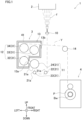
- FIG. 1 is a schematic diagram of the spun yarn take-up machine 1.
- the spun yarn take-up machine 1 is structured so that yarns Y spun out from a spinning apparatus 2 are drawn by a spun yarn drawing apparatus 3 and then are wound up by a yarn winding apparatus 4.
- the spinning apparatus 2 is configured to produce nylon yarns Y by continuously spinning out molten polymer made of nylon (e.g., nylon 6 or nylon 66).
- FIG. 1 shows only one yarn Y.
- Each yarn Y is, e.g., a multi-filament yarn formed of plural filaments f. Alternatively, each yarn Y may be formed of one filament f.
- oil is applied by an oil guide 10. The yarns Y are then sent to the spun yarn drawing apparatus 3.
- the spun yarn drawing apparatus 3 is an apparatus for drawing the yarns Y.
- the spun yarn drawing apparatus 3 is provided below the spinning apparatus 2.
- the spun yarn drawing apparatus 3 includes a non-heating roller group 11, a heating roller group 12, and a thermal insulation box 13.
- the yarns Y are drawn between plural non-heating rollers 21 included in the non-heating roller group 11 and plural heating rollers 31 included in the heating roller group 12.
- Each heating roller 31 is a thermal setting roller for thermally setting the drawn yarns Y.
- the heating rollers 31 are housed in the thermal insulation box 13.
- the thermal insulation box 13 includes an entrance 13a and an exit 13b.
- the entrance 13a is an opening formed in order to introduce the yarns Y into the thermal insulation box 13.
- a part of an accompanied flow (hereinafter, yarn accompanied flow) generated by running of the yarns Y flows into the thermal insulation box 13 through the entrance 13a.
- the exit 13b is an opening formed in order to take the yarns Y, which are drawn and heated, out from the thermal insulation box 13.
- a part of a yarn accompanied flow flows out from the thermal insulation box 13 through the exit 13b.
- the spun yarn drawing apparatus 3 will be detailed later.
- the yarns Y drawn by the spun yarn drawing apparatus 3 are sent to the yarn winding apparatus 4 via a guide roller 14.
- the yarn winding apparatus 4 is configured to wind the yarns Y onto the respective winding bobbins Bw, so as to form plural packages P.
- a series of steps of spinning out, drawing, and winding of the yarns Y is performed by the spun yarn take-up machine 1 structured as described above.
- FIG. 2 is a cross section of the spun yarn drawing apparatus 3, which is orthogonal to the front-rear direction.
- the spun yarn drawing apparatus 3 includes the non-heating roller group 11, the heating roller group 12, and the thermal insulation box 13.
- the non-heating roller group 11 is configured to take up the oiled yarns Y, and to send the yarns Y to the heating roller group 12 without heating the yarns Y.
- an unillustrated take-up roller may be provided between the oil guide 10 and the non-heating roller group 11 in the yarn running direction.
- the non-heating roller group 11 includes the non-heating rollers 21.
- the non-heating rollers 21 are provided outside the thermal insulation box 13.
- the non-heating rollers 21 may be housed in a thermal insulation box (not illustrated) different from the thermal insulation box 13.
- Each non-heating roller 21 is, e.g., a known godet roller. Each non-heating roller 21 is rotationally driven by an unillustrated motor. The rotational axis direction of the non-heating rollers 21 is substantially parallel to, e.g., the front-rear direction. That is, the rotational axes of the non-heating rollers 21 are substantially parallel to one another. Each non-heating roller 21 includes an outer circumferential surface 21a (see FIG. 1 ) onto which the yarns Y are wound. The yarns Y are aligned and wound onto the outer circumferential surface 21a in the rotational axis direction of each non-heating roller 21.
- the yarns Y are wound onto the non-heating rollers 21 in order from the upstream side in the yarn running direction, at a winding angle of less than 360 degrees.
- the non-heating rollers 21 three non-heating rollers 21 are provided (see FIG. 1 ) in the present embodiment.
- a first non-heating roller 22, a second non-heating roller 23, and a third non-heating roller 24 are provided in this order from the upstream side in the yarn running direction.
- the number of the non-heating rollers 21 is not limited to this.
- the heating roller group 12 is configured to draw the yarns Y with the non-heating roller group 11, and to thermally set the drawn yarns Y.
- the heating roller group 12 includes the heating rollers 31.
- the heating rollers 31 are housed in the thermal insulation box 13. Being similar to the non-heating rollers 21, each heating roller 31 is, e.g., a known godet roller.
- Each heating roller 31 is rotationally driven by an unillustrated motor.
- the rotational axis direction of the heating rollers 31 is substantially parallel to, e.g., the front-rear direction.
- each heating roller 31 includes an outer circumferential surface 31a (see FIG. 2 ) onto which the yarns Y are wound. The yarns Y are aligned and wound onto the outer circumferential surface 31a in the rotational axis direction of each heating roller 31.
- Each heating roller 31 includes an unillustrated heater.
- the heater includes, e.g., an unillustrated coil. The heater is configured to heat the outer circumferential surface 31a of each heating roller 31 by means of Joule heat when power is supplied to the coil.
- the heating temperatures of the heating rollers 31 are substantially identical with one another.
- the heating temperature of each heating roller 31 is, e.g., 50 to 250 °C.
- the yarns Y are wound onto the heating rollers 31 in order from the upstream side in the yarn running direction, at a winding angle of less than 360 degrees.
- three heating rollers 31 are provided in the present embodiment.
- a first heating roller 32, a second heating roller 33, and a third heating roller 34 are provided in this order from the upstream side in the yarn running direction.
- the first heating roller 32 (the most upstream heating roller and an upstream heating roller in the present invention) is provided on the most upstream side in the yarn running direction.
- the first heating roller 32 is provided below the remaining two heating rollers 31.
- the third non-heating roller 24 is provided on the most downstream side in the yarn running direction.
- the first heating roller 32 is provided immediately downstream of the third non-heating roller 24.
- the first heating roller 32 is configured to draw the yarns Y with the third non-heating roller 24.
- the yarn feeding speed of the first heating roller 32 is set to be higher than that of the third non-heating roller 24.
- the yarns Y are drawn on account of a difference in yarn feeding speed between the first heating roller 32 and the third non-heating roller 24. In the present embodiment, the yarns Y are drawn on the upstream side of the first heating roller 32 in the yarn running direction.
- the second heating roller 33 (the upstream heating roller, a predetermined upstream heating roller, a predetermined heating roller, and an intermediate heating roller in the present invention) is provided downstream of the first heating roller 32 and upstream of the third heating roller 34 in the yarn running direction.
- the second heating roller 33 is provided above and to the right of the first heating roller 32.
- the second heating roller 33 is provided to the right of and slightly below the third heating roller 34.
- the yarn feeding speed of the second heating roller 33 is substantially identical with that of the first heating roller 32.
- the third heating roller 34 (a downstream heating roller and the most downstream heating roller in the present invention) is provided on the most downstream side in the yarn running direction.
- the third heating roller 34 is provided immediately above the first heating roller 32.
- the third heating roller 34 is provided to the left of and slightly above the second heating roller 33.
- the yarn feeding speed of the third heating roller 34 is substantially identical with, e.g., that of the first heating roller 32 and that of the second heating roller 33.
- the yarn feeding speed of the third heating roller 34 is not limited to this.
- each of the first heating roller 32, the second heating roller 33, and the third heating roller 34 is indicated by arrows in FIG. 2 , for example.
- the rotational direction of the first heating roller 32 is a clockwise direction in a cross section orthogonal to the front-rear direction.
- the rotational direction of the second heating roller 33 is opposite to that of the first heating roller 32 (i.e., is a counterclockwise direction).
- the rotational direction of the third heating roller 34 is opposite to that of the second heating roller 33 and the same as that of the first heating roller 32 (i.e., is a clockwise direction).
- the thermal insulation box 13 is a box for suppressing heat of the heating rollers 31 from escaping to the outside. As shown in FIG. 2 , the thermal insulation box 13 includes a circumferential wall 41, a backside wall 42, flow control members 43 to 46, shielding members 47 and 48, a returning path 49, and a front door (not illustrated) .
- the internal space of the thermal insulation box 13 is filled with gas (air) whose pressure is substantially identical with that of gas (air) in the space outside the thermal insulation box 13.
- the circumferential wall 41 is a wall-like member surrounding the heating rollers 31 in a cross section orthogonal to the front-rear direction (see FIG. 2 ).
- the circumferential wall 41 includes inner wall surfaces 41a to 41h which are provided to surround the heating rollers 31.
- the inner wall surfaces 41a to 41h extend along, e.g., the front-rear direction (a direction perpendicular to the plane of FIG. 2 ).
- the inner wall surface 41a is provided to the right of the first heating roller 32, faces to the left, and extends along the up-down direction.
- the inner wall surface 41a is provided immediately above the entrance 13a.
- the inner wall surface 41b is provided to the right of the first heating roller 32, faces to the left, and extends along the up-down direction.
- the inner wall surface 41b is provided immediately below the entrance 13a.
- the inner wall surface 41c is provided below the first heating roller 32, faces up, and extends along the left-right direction. A right end of the inner wall surface 41c is connected to a lower end of the inner wall surface 41b.
- the inner wall surface 41d is provided to the left of the first heating roller 32 and the third heating roller 34, faces to the right, and extends along the up-down direction.
- a lower end of the inner wall surface 41d is connected to a left end of the inner wall surface 41c.
- the inner wall surface 41e is provided to the right of the first heating roller 32 and below the second heating roller 33, faces up, and extends along the left-right direction.
- a left end of the inner wall surface 41e is connected to an upper end of the inner wall surface 41a.
- the inner wall surface 41f is provided to the right of the second heating roller 33, faces to the left, and extends along the up-down direction.
- a lower end of the inner wall surface 41f is connected to a right end of the inner wall surface 41e.
- the inner wall surface 41g is provided above the second heating roller 33 and the third heating roller 34, faces down, and extends along the left-right direction.
- a left end of the inner wall surface 41g is connected to an upper end of the inner wall surface 41d.
- the inner wall surface 41h is provided to the right of the second heating roller 33, faces to the left, and extends along the up-down direction.
- the inner wall surface 41h is provided immediately above the exit 13b.
- An upper end of the inner wall surface 41h is connected to a right end of the inner wall surface 41g.
- the arrangement of the inner wall surfaces 41a to 41h is not limited to the above-described arrangement.
- the backside wall 42 (see FIG. 2 ) is a wall provided behind the circumferential walls 41.
- the backside wall 42 is a plate-shaped member provided to be, e.g., substantially perpendicular to the front-rear direction.
- the backside wall 42 is connected to rear ends of the inner wall surfaces 41a to 41h.
- the position of a motor (not illustrated) configured to rotationally drive each heating roller 31 is fixed relative to, e.g., the backside wall 42.
- the flow control members 43 to 46 are members for adjusting airflows in the thermal insulation box 13.
- the flow control members 43 to 46 are members for mainly adjusting the above-described yarn accompanied flow and an accompanied flow generated by the rotation of each heating roller 31 (hereinafter, a roller accompanied flow).
- the flow control members 43 to 46 are formed by, e.g., bending plate-shaped members. Alternatively, at least one of the flow control members 43 to 46 may be formed by, e.g., cutting a block-shaped member.
- the flow control members 43 to 46 extend along, e.g., the front-rear direction (a direction perpendicular to the plane of FIG. 2 ).
- the flow control members 43 to 46 are fixed to, e.g., the backside wall 42.
- the flow control member 43 is provided to enclose a left part of the first heating roller 32.
- the flow control member 43 extends substantially in the up-down direction.
- the flow control member 43 is provided above and distanced from the inner wall surface 41c in the up-down direction.
- the flow control member 43 is provided to the right of the inner wall surface 41d and distanced from the inner wall surface 41d in the left-right direction. With this arrangement, the returning path 49 is formed between the flow control member 43 and the inner wall surface 41d.
- the flow control member 44 is provided to mainly enclose a lower part of the second heating roller 33.
- the flow control member 44 extends substantially in the left-right direction. For example, approximately the entire flow control member 44 is provided above the inner wall surface 41e.
- a shielding portion 44a extending to the vicinity of an outer circumferential surface 32a of the first heating roller 32 is provided at a left end portion of the flow control member 44.
- the yarns Y are not wound onto a part of the outer circumferential surface 32a, and the shielding portion 44a extends toward this part of the outer circumferential surface 32a.
- the shielding portion 44a is configured to shield a roller accompanied flow of the first heating roller 32 so that the roller accompanied flow is suppressed from returning to the entrance 13a side.
- a right end of the flow control member 44 is connected to, e.g., a lower part of the inner wall surface 41f.
- the flow control member 44 and the inner wall surface 41f form an accompanied flow regulating surface 51 described later.
- the flow control member 45 is provided to mainly enclose an upper part of the second heating roller 33.
- the flow control member 45 extends substantially in the left-right direction.
- the flow control member 45 is provided above the second heating roller 33 and below the inner wall surface 41g in the up-down direction.
- a shielding portion 45a extending to the vicinity of an outer circumferential surface 34a of the third heating roller 34 is provided at a left end portion of the flow control member 45.
- the shielding portion 45a is configured to shield a roller accompanied flow of the third heating roller 34 so that the roller accompanied flow returns to the second heating roller 33 side.
- a right end of the flow control member 45 is connected to, e.g., an upper end portion of the inner wall surface 41f.
- the flow control member 45, the inner wall surface 41f, and the flow control member 44 form the accompanied flow regulating surface 51 described later.
- the flow control member 46 (a partition portion of the present invention) is provided to separate the first heating roller 32 from the third heating roller 34 in the up-down direction.
- the flow control member 46 extends substantially in the left-right direction. For example, approximately the entire flow control member 46 is provided above the first heating roller 32 and below the third heating roller 34 (i.e., between the first heating roller 32 and the third heating roller 34) in the up-down direction.
- the flow control member 46 is provided to the right of the inner wall surface 41d and distanced from the inner wall surface 41d in the left-right direction.
- the shielding member 47 is configured to block a yarn accompanied flow generated by running of the yarns Y entering the thermal insulation box 13 through the entrance 13a.
- the shielding member 47 is, e.g., a plate-shaped member.
- the shielding member 47 is fixed to, e.g., the inner wall surface 41c and the backside wall 42.
- the yarns Y are wound onto a part of the of the outer circumferential surface 32a, and the shielding member 47 extends toward this part of the outer circumferential surface 32a in the circumferential direction of the first heating roller 32.
- the shielding member 48 (a shielding portion of the present invention) is configured to suppress a yarn accompanied flow and a roller accompanied flow of the third heating roller 34 from flowing out from the exit 13b by blocking the yarn accompanied flow and this roller accompanied flow.
- the shielding member 48 is, e.g., a plate-shaped member.
- the shielding member 48 is fixed to, e.g., the inner wall surface 41d and the backside wall 42.
- the yarns Y are wound onto a part of the outer circumferential surface 34a of the third heating roller 34 (the most downstream contact surface 34b), and the shielding member 48 extends from an upper part of the inner wall surface 41d toward this part of the outer circumferential surface 34a.
- the returning path 49 is, e.g., a path for allowing air near the third heating roller 34 to return to the vicinity of the first heating roller 32.
- the returning path 49 causes a space (a downstream space of the present invention) on the third heating roller 34 side of the flow control member 46 to communicate with a space (an upstream space of the present invention) on the first heating roller 32 side of the flow control member 46.
- An entrance 49a of the returning path 49 is formed between the inner wall surface 41d and a left end of the flow control member 46.
- An exit 49b of the returning path 49 is formed between (i) a lower end of the flow control member 43 and (ii) the inner wall surfaces 41c and 41d.
- the front door (not illustrated) is a door for closing the front of the thermal insulation box 13.
- the front door is arranged to make contact with a front end surface of the circumferential wall 41. A slight gap is formed between the front door and the heating rollers 31.
- the thermal insulation box 13 includes an outlet (not illustrated) for exhausting gas including oil mist applied to the yarns Y.
- a flow rate of gas exhausted from the outlet is sufficiently smaller than that of gas flowing in from the entrance 13a and that of gas flowing out from the exit 13b.
- the outlet is not further detailed in this description.
- the spun yarn drawing apparatus 3 described above is required to suppress (i) yarn swing and (ii) increase in power consumption of the heaters.
- the spun yarn drawing apparatus 3 includes the three heating rollers 31 (e.g., godet rollers) as described above. With this arrangement, the nylon yarns Y are sufficiently heated without using a known Nelson-type roller in which the yarn swing is likely to occur. It is therefore possible to suppress the yarn swing.
- the power consumption of the heaters can be reduced by, e.g., increasing a heat retaining effect of the thermal insulation box 13 and that of the heating rollers 31.
- the heat retaining effect of the thermal insulation box 13 and that of the heating rollers 31 can be increased by suppressing, e.g., the escape of heat of the thermal insulation box 13 and/or the entry of cool air from the outside of the thermal insulation box 13.
- the spun yarn drawing apparatus 3 is structured as described below.
- FIG. 3(a) and FIG. 3(b) are an enlarged view of the second heating roller 33 and its surroundings.
- the rotational axis direction of the second heating roller 33 is simply referred to as the rotational axis direction.
- the radial direction of the second heating roller 33 is simply referred to as the radial direction.
- the circumferential direction of the second heating roller 33 is simply referred to as the circumferential direction.
- the yarns Y are in contact with a part of an outer circumferential surface 33a of the second heating roller 33, and this part of the outer circumferential surface 33a is referred to as a contact surface 33b (indicated by a bold line in FIG. 3 (a) ) in a cross section orthogonal to the rotational axis direction (see FIG. 3(a) and FIG. 3(b) ; hereinafter, the above-described cross section).
- the yarns Y are not in contact with another part of the outer circumferential surface 33a, and this part of the outer circumferential surface 33a is referred to as a contactless surface 33c (indicated by a bold line in FIG. 3(b) ) in the above-described cross section.
- the most upstream part of the contact surface 33b in the yarn running direction is referred to as a contact start point PS (see FIG. 3(a) ) in the above-described cross section.
- the most downstream part of the contact surface 33b in the yarn running direction is referred to as a contact end point PE (see FIG. 3(a) ) in the above-described cross section.
- the paths of the yarns Y are referred to as yarn paths.
- a circulator 50 (a predetermined circulator of the present invention) is provided in the vicinity of the second heating roller 33 in order to cause a roller accompanied flow of the second heating roller 33 to circulate around the second heating roller 33.
- the circulator 50 is formed by, e.g., the above-described inner wall surface 41f of the circumferential wall 41 and the flow control members 44, 45, and 46.
- the circulator 50 includes, e.g., the accompanied flow regulating surface 51 (indicated by bold lines in FIG. 3(a) ) and an accompanied flow collecting surface 52 (indicated by a bold line in FIG. 3(b) ).
- the accompanied flow regulating surface 51 is a surface for suppressing a roller accompanied flow flowing in the vicinity of the contact surface 33b from flowing outward in the radial direction.
- the accompanied flow regulating surface 51 is formed by, e.g., the inner wall surface 41f and the flow control members 44 and 45.
- the accompanied flow regulating surface 51 is provided outside the contact surface 33b in the radial direction so as to enclose the contact surface 33b in the circumferential direction.
- the phrase "enclose the contact surface 33b" means that the accompanied flow regulating surface 51 extends to cover at least the contact surface 33b in the circumferential direction.
- the accompanied flow regulating surface 51 extends at least from the position of one end of the contact surface 33b to that of the other end of the contact surface 33b in the circumferential direction.
- the accompanied flow regulating surface 51 makes it possible to prevent, e.g., a roller accompanied flow from flowing toward the exit 13b (see FIG. 2 ) .
- the accompanied flow collecting surface 52 is a surface for allowing a roller accompanied flow flowing in the vicinity of the contactless surface 33c to be guided in the circumferential direction and to return to the upstream side in the yarn running direction (i.e., to be collected).
- the accompanied flow collecting surface 52 is formed of, e.g., the flow control member 46.
- a guide portion 46a is formed at a right end portion of the flow control member 46 so as to be substantially triangular in shape in the above-described cross section.
- the accompanied flow collecting surface 52 is closest to the contactless surface 33c in the radial direction.
- the accompanied flow collecting surface 52 faces the contactless surface 33c in the radial direction in the above-described cross section.
- the accompanied flow collecting surface 52 is distanced from the accompanied flow regulating surface 51 in the circumferential direction.
- the contactless surface 33c is provided between (i) yarn paths (hereinafter, these yarn paths are referred to as upstream yarn paths) provided upstream of the contact start point PS in the yarn running direction and (ii) yarn paths (hereinafter, these yarn paths are referred to as downstream yarn paths) provided downstream of the contact end point PE in the yarn running direction.
- the accompanied flow collecting surface 52 is straight (substantially linear) in the above-described cross section.
- the accompanied flow collecting surface 52 forms a line segment L1 (indicated by a bold line in FIG. 3(b) ) which is substantially linear and which connects the first point P1 to the second point P2.
- a line segment is a straight line with both ends.
- each line segment, etc. contained in a surface formed by a member is simply referred to as a line segment, etc.
- each line segment, etc. which is independent from the member and which is virtually drawn is referred to as a virtual line segment, etc.
- a virtual straight line which contains the contact start point PS and which partially overlaps the upstream yarn paths is defined as a virtual upstream straight line VLu in the above-described cross section.
- a virtual straight line which contains the contact end point PE and which partially overlaps the downstream yarn paths is defined as a virtual downstream straight line VLd in the above-described cross section.
- the center of the second heating roller 33 in the radial direction is referred to as a center point PC in the above-described cross section.
- the virtual upstream straight line VLu is line-symmetric with the virtual downstream straight line VLd about, e.g., a predetermined symmetry axis VLs passing the center point Pc.
- the first point P1 is provided between the symmetry axis VLs and the virtual downstream straight line VLd in the above-described cross section.
- a virtual line segment connecting the first point P1 to the second point P2 is defined as a first virtual line segment VL1 in the above-described cross section.
- the first virtual line segment VL1 overlaps the line segment L1.
- a virtual line segment connecting the above-described center point Pc to the first point P1 is defined as a second virtual line segment VL2.
- an angle ⁇ 1 between the first virtual line segment VL1 and the second virtual line segment VL2 is an acute angle.
- a virtual half-line VHL whose endpoint is the first point P1 and which passes the second point P2 intersects with, e.g., the accompanied flow regulating surface 51 in the above-described cross section.
- a half-line is a straight line with only one endpoint.
- An intersection between the virtual half-line VHL and yarn paths of the yarns Y running toward the contact start point PS is defined as a third point P3 in the above-described cross section.
- a virtual line segment connecting the second point P2 to the third point P3 is defined as a third virtual line segment VL3.
- a virtual line segment connecting the third point P3 to the contact start point Ps is defined as a fourth virtual line segment VL4.
- An angle ⁇ 2 between the third virtual line segment VL3 and the fourth virtual line segment VL4 is, e.g., an obtuse angle.
- the circulator 50 structured as described above makes it possible to cause a roller accompanied flow to circulate around the entire second heating roller 33 in the circumferential direction (indicated by a dashed-line arrow A1 of FIG. 3(a) ).
- This suppresses a roller accompanied flow generated around the second heating roller 33 from moving away from the second heating roller 33 because of a centrifugal force and flowing out from the exit 13b.
- This roller accompanied flow includes air heated by the second heating roller 33. That is, the flow-out of heated air from the exit 13b is suppressed by the circulator 50.
- the decrease in pressure of the thermal insulation box 13 is also suppressed.
- the circulator 50 allows the roller accompanied flow to smoothly circulate without being blocked. That is, the circulator 50 is configured to cause the roller accompanied flow to circulate around the second heating roller 33 so that a layer flow along the yarn running direction is generated around the second heating roller 33. It is therefore possible to further suppress the yarn swing.
- the present inventors performed fluid analysis regarding a heat retaining effect of the circulator 50 in the thermal insulation box 13. Furthermore, the present inventors evaluated how much power consumption of the heaters of the heating rollers 31 was reduced by this heat retaining effect. The following will describe the details.
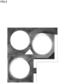
- FIG. 4 shows a simulation result of a flow rate of fluid.
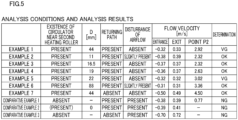
- FIG. 5 is a table showing (i) later-described conditions of Examples 1 to 7 and Comparative Examples 1 to 3, and (ii) results of the fluid analysis under each set of conditions.
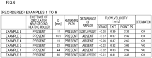
- FIG. 6 shows the analysis results of the fluid analysis in regard to Examples 1 to 6, which are picked up from the table of FIG. 5 and which are reordered in an ascending order of a later-described distance D.
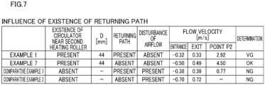
- FIG. 7 shows the conditions and analysis results of the fluid analysis in regard to Examples and Comparative Examples regarding the existence of the returning path 49 and are picked up from the table of FIG. 5 .
- FIG. 8(a) is used for explaining Comparative Example 1.
- FIG. 8(b) is used for explaining Comparative Example 2.
- the present inventors created a model of the above-described spun yarn drawing apparatus 3 (i.e., the non-heating roller group 11, the heating roller group 12, and the thermal insulation box 13) by using a typical software for the fluid analysis.
- the present inventors performed a simulation of a flow rate of fluid mainly in the thermal insulation box 13 (see FIG. 4 ).
- the present inventors set the following conditions to be constant: the number, sizes, positions, and circumferential speeds of the non-heating rollers 21 belonging to the non-heating roller group 11; and the number, sizes, positions, and circumferential speeds of the heating rollers 31 belonging to the heating roller group 12.
- the number of the heating rollers 31 was set to three.
- the diameter of each heating roller 31 was set to 300 mm.
- the arrangement of the heating rollers 31 was the same as described above (see FIG. 2 ).
- the circumferential speed of each heating roller 31 was set to 4690 m/min.
- the outlet (for exhausting gas including mist) of the thermal insulation box 13 was closed. These conditions were set for the sake of convenience. Note that the heat retaining effect of the thermal insulation box 13 and that of each heating roller 31 are not significantly affected by these conditions.
- Examples 1 to 6 ware set to have different shortest distances each of which was the shortest distance (the distance D shown in FIG. 3(b) ) between the accompanied flow collecting surface 52 and the outer circumferential surface 33a in the above-described cross section.
- the distance D is the smallest distance between a given point on the accompanied flow collecting surface 52 and a given point on the outer circumferential surface 33a in the above-described cross section.
- the distance D is the shortest distance between (i) a virtual tangent VL5 which is a given tangent to the outer circumferential surface 33a and which is in parallel to the accompanied flow collecting surface 52 and (ii) the accompanied flow collecting surface 52.
- VL5 virtual tangent to the outer circumferential surface 33a and which is in parallel to the accompanied flow collecting surface 52 and (ii) the accompanied flow collecting surface 52.
- the present inventors changed three sides of a triangle of the guide portion 46a in the above-described cross section while maintaining angles of the triangle. Except the above-described points, Examples 1 to 6 and Comparative Example 1 and 2 are not different from the spun yarn drawing apparatus 3.
- the distance D is 44 mm in Example 1.
- the distance D is 11 mm in Example 2.
- the distance D is 16.5 mm in Example 3.
- the distance D is 19 mm in Example 4.
- the distance D is 22 mm in Example 5.
- the distance D is 88 mm in Example 6. That is, the analysis results were obtained in regard to Examples in each of which the distance D was 11 mm or more and 88 mm or less.
- Comparative Example 1 For comparison to Examples 1 to 6, the present inventors performed the analysis in Comparative Examples 1 and 2 under the following conditions.
- Comparative Example 1 the present inventors performed the analysis while the circulator 50 was not provided in the vicinity of the second heating roller 33.
- a shielding member 53 is provided so as to extend from the accompanied flow collecting surface 52 to the outer circumferential surface 33a in Comparative Example 1. In this case, a roller accompanied flow does not smoothly circulate around the second heating roller 33.
- the analysis conditions of Comparative Example 1 are the same as those of Example 1 (see FIG. 5 ).
- Comparative Example 2 the present inventors performed the analysis while the distance D was zero. To be more specific, as shown in FIG.
- a guide portion 46a1 is provided instead of the guide portion 46a in Comparative Example 2.
- the guide portion 46a1 includes an accompanied flow collecting surface 52a, with the distance D being substantially zero. In this case, a roller accompanied flow almost never circulates around the second heating roller 33.
- the circulator 50 is "PRESENT" (shown in parentheses in FIG. 5 ), the circulator 50 does not function substantially.
- the present inventors performed the analysis in order to check whether the returning path 49 may not be provided in the thermal insulation box 13. Irrespective of whether the returning path 49 was provided in the thermal insulation box 13, whether the presence of the circulator 50 made an improvement was analyzed as compared to cases where the circulator 50 was not provided.
- the present inventors performed the analysis as follows in regard to Example 7 and Comparative Example 3 in each of which the returning path 49 was not provided (to be more specific, the entrance 49a was closed) . Except the absence of the returning path 49, the analysis conditions of Example 7 are the same as those of Example 1 (see FIG. 5 and FIG. 7 ). Except the absence of the returning path 49, the analysis conditions of Comparative Example 3 are the same as those of Comparative Example 1 (see FIG. 5 and FIG. 7 ).
- FIG. 4 shows a simulation result of Example 1 as representative one.
- the flow velocity of air is low in dark areas (i.e., the flow rate of air is small) and high in white areas (i.e., the flow rate of air is large) .
- the present inventors checked whether a whirl was generated in the thermal insulation box 13 in regard to each simulation result, and determined whether an airflow was disturbed in each set of conditions. The disturbance of the airflow may cause yarn breakage.
- the present inventors evaluated the disturbance of the airflow in three stages, i.e., "ABSENT”, “SLIGHTLY PRESENT", and “PRESENT” (see FIG. 5 and FIG. 6 ).
- ABSENT "SLIGHTLY PRESENT”
- PRESENT the disturbance of the airflow was evaluated as "ABSENT” or "SLIGHTLY PRESENT”
- the present inventors performed a final determination in consideration of a heat retaining effect described later.
- the disturbance of the airflow is evaluated as "PRESENT”
- the present inventors made a determination as "NG”, irrespective of the magnitude of the heat retaining effect.
- the present inventors obtained simulation values of a flow velocity of air (hereinafter, this will be simply referred to as the flow velocity) at three points in the thermal insulation box 13 (see FIG. 5 to FIG. 7 ). These three points are a point in the vicinity of the entrance 13a, a point in the vicinity of the exit 13b, and a point in the vicinity of the above-described second point P2 (see FIG. 3(b) ).
- the unit of the flow velocity is m/s.
- the present inventors set evaluation criteria of the flow velocity at the above-described three points as follows.
- the flow velocity in the vicinity of the entrance 13a was -0.50 m/s or more
- the flow velocity was determined as good (i.e., the flow rate of cool air was small).
- the flow velocity in the vicinity of the exit 13b was 0.50 m/s or less
- the flow velocity was determined as good (i.e., the flow rate of warm air was small).
- the flow velocity in the vicinity of the second point P2 was 2.00 m/s or more
- the flow velocity was determined as good (i.e., the flow rate of circulating gas was large).
- the heat retaining effect of the thermal insulation box 13 is high.
- Example 1 was “VG”.
- Examples 2, 3, 4, 6 as “OK” and Example 5 were “VG”.
- Examples 1 to 6 in each of which the circulator 50 and the returning path 49 were provided were determined as "OK” or "VG”.
- Example 7 The following analysis results were obtained in regard to Example 7 in which the thermal insulation box 13 was provided with the circulator 50 and not provided with the returning path 49.
- the flow velocity was - 0.50 m/s in the vicinity of the entrance 13a, -0.49 m/s in the vicinity of the exit 13b, and 4.50 m/s in the vicinity of the second point P2.
- the disturbance of the airflow was "ABSENT”.
- the present inventors determined that Example 7 was "OK".
- Comparative Example 1 the flow velocity was less than 2.00 m/s in the vicinity of the second point P2. Furthermore, the disturbance of the airflow was "PRESENT". The present inventors determined that Comparative Example 1 was "NG”. In Comparative Example 2 (see FIG. 5 ), the flow velocity was not calculated in the vicinity of the second point P2. Furthermore, the disturbance of the airflow was "PRESENT". The present inventors determined that Comparative Example 2 was "NG”. In Comparative Example 3, the flow velocity was -0.70 m/s in the vicinity of the entrance 13a and 0.72 m/s in the vicinity of the exit 13b. Furthermore, the flow velocity was not calculated in the vicinity of the second point P2. In addition to that, the disturbance of the airflow was "PRESENT". The present inventors determined that Comparative Example 3 was "NG”.
- Example 1 The following will describe the evaluations and results of power consumption of the heaters.
- the present inventors created an apparatus corresponding to Example 1 and that corresponding to Comparative Example 1, and then measured and calculated the total power consumption of the heaters of the three heating rollers while rollers of each apparatus were driven under conditions similar to the analysis conditions.
- the surface temperature of each heating roller was set to 170 °C.
- the total power consumption was 1.4kW.
- Comparative Example 1 the total power consumption was 2.1kW. This showed that the power consumption was reduced at least in Example 1 as compared to Comparative Example 1.
- the conditions of Comparative Example 1 are the same as those of Example 1 as described above. Because the circulator 50 is provided in each of other Examples, the power consumption is presumably reduced in other Examples.
- the circulator 50 causes a roller accompanied flow to circulate around the second heating roller 33 so that the gas heated by the second heating roller 33 is suppressed from escaping from the thermal insulation box 13 through the exit 13b of the yarns Y. This increases the heat retaining effect of the thermal insulation box 13.
- a roller accompanied flow is circulated by the circulator 50 so that air of a roller accompanied flow is kept heated by the second heating roller 33. This increases a heat retaining effect around the second heating roller 33, and thus increases that of the second heating roller 33 itself. Therefore, the increase in power consumption is suppressed in the spun yarn drawing apparatus 3 while the yarn swing is suppressed.
- the three heating rollers 31 may have different yarn feeding speeds. With this arrangement, the tension applied to the yarns Y is intentionally increased, or the yarns Y are intentionally relaxed. This makes it possible to control yarn quality.
- a roller accompanied flow circulates around the second heating roller 33 so as to cause a stable layer flow. Therefore, even when the flow rate of circulating gas is large, the yarn swing is suppressed.
- the accompanied flow collecting surface 52 makes it possible to suppress a roller accompanied flow from flowing outward of the outer circumferential surface 33a in the radial direction because of a centrifugal force. It is therefore possible to effectively circulate a roller accompanied flow with a simple structure.
- the first point P1 is provided in the vicinity of the contact end point PE.
- an accompanied flow flowing in the vicinity of the contact end point PE is easily taken in (collected) by the accompanied flow collecting surface 52. It is therefore possible to effectively circulate a roller accompanied flow.
- the angle ⁇ 1 between the first virtual line segment VL1 and the second virtual line segment VL2 is an acute angle.
- the accompanied flow collecting surface 52 forms the line segment L1 connecting the first point P1 to the second point P2. This allows a roller accompanied flow to smoothly flow along the accompanied flow collecting surface 52. Furthermore, the accompanied flow collecting surface 52 is formed by a simple process as compared to a case where the accompanied flow collecting surface 52 is curved or bent.
- the circulator 50 includes the accompanied flow regulating surface 51. With this arrangement, a roller accompanied flow is further suppressed from flowing outward of the outer circumferential surface 33a in the radial direction because of a centrifugal force.
- the virtual half-line VHL intersects with the accompanied flow regulating surface 51.
- a roller accompanied flow guided by the accompanied flow collecting surface 52 is supplied toward the accompanied flow regulating surface 51. It is therefore possible to further effectively circulate a roller accompanied flow.
- the angle ⁇ 2 between the third virtual line segment VL3 and the fourth virtual line segment VL4 is an obtuse angle.
- the shortest distance (distance D) between the outer circumferential surface 33a and the accompanied flow collecting surface 52 is preferably 11 mm or more and 88 mm or less.
- the most upstream one (i.e., the first heating roller 32) of the heating rollers 31 in the yarn running direction is easily cooled by cool air flowing in from the entrance 13a formed in the thermal insulation box 13.
- the thermal insulation box 13 preferably includes the returning path 49.
- the circulator 50 is provided around the second heating roller 33.
- a yarn accompanied flow also flows in the thermal insulation box 13.
- the most upstream first heating roller 32 in the yarn running direction is easily cooled by such cool air entering the thermal insulation box 13 from outside.
- the second heating roller 33 is relatively close to the first heating roller 32, heat from the second heating roller 33 is transmitted to the first heating roller 32 side by increasing the heat retaining effect of the second heating roller 33. It is therefore possible to increase the heat retaining effect of the first heating roller 32.
- the shielding member 48 makes it possible to suppress a yarn accompanied flow from flowing out from the thermal insulation box 13 through the exit 13b. It is therefore possible to increase the heat retaining effect of the thermal insulation box 13.
- the yarns Y are drawn on the upstream side of the first heating roller 32 in the yarn running direction. Because three or more heating rollers 31 are provided downstream of an area where the yarns Y are drawn in the yarn running direction, the yarns Y are sufficiently gripped. With this arrangement, the tension applied to the drawn yarns Y is suppressed from causing the yarns Y to slip on the heating rollers 31. It is therefore possible to further suppress the yarn swing.
- the thermal insulation box 13 makes it possible to suppress heat transfer between the third non-heating roller 24 and the first heating roller 32. Therefore, even when the heating temperature of the third non-heating roller 24 is significantly different from that of the first heating roller 32, the influence of a temperature difference is suppressed.
- the thermal insulation box 13 does not need to house the non-heating rollers 21. Therefore, the internal structure of the thermal insulation box 13 is freely designed as compared to a case where, e.g., heating rollers (not illustrated) are housed in the thermal insulation box 13 instead of the non-heating rollers 21. In this regard, the unillustrated heating rollers are different in set temperature from the heating rollers 31.
- thermal setting rollers 31 Three or more thermal setting rollers (heating rollers 31) are provided. It is therefore possible to thermally set the yarns Y sufficiently without using a Nelson roller in which the yarn swing is likely to occur.
- the arrangement of the present embodiment is especially effective to draw the nylon yarns Y.
- Modification 2 When a modification has the same structure as Modification 1 except that the returning path 49 is not provided in the thermal insulation box 13, this modification is referred to as Modification 2.
- the flow velocity of gas was -0.49 m/s in the vicinity of the entrance 13a and 0.48 m/s in the vicinity of the exit 13b.
- the analysis results of Modification 2 ware good. The present inventors determined that Modification 2 was "OK".
- the circulator 50 is provided to correspond to the second heating roller 33.
- Another circulator may be provided to correspond to the first heating roller 32.
- the first heating roller 32 is equivalent to the predetermined upstream heating roller of the present invention in addition to the second heating roller 33.
- the following surfaces are included in an accompanied flow regulating surface of the present invention: the inner wall surface 41c; and a wall surface 43a of the flow control member 43 on the first heating roller 32 side.
- an accompanied flow collecting surface 44Ma is formed at a left end portion of a flow control member 44M provided instead of the flow control member 44.
- the accompanied flow collecting surface 44Ma is curved along the outer circumferential surface 32a of the first heating roller 32.
- a backward flow prevention wall 54 may be provided in the vicinity of the entrance 13a so that, e.g., air is prevented from flowing backward in the thermal insulation box 13 and flowing out from the entrance 13a.
- the backward flow prevention wall 54 may be provided with an accompanied flow collecting surface 54a which is functionally identical with the accompanied flow collecting surface 44Ma.
- the above-described shielding member 47 see FIG. 2
- This modification is referred to as Modification 3 (see FIG. 11 ).
- the distance D is 44 mm and identical with that in Example 1.
- the returning path 49 is provided in the thermal insulation box 13.
- a cell in the "OTHERS" column stores "CONDITION B" with respect to the row of Modification 3.
- the "CONDITION B” indicates that a circulator is provided to correspond to the first heating roller 32.
- the flow velocity of gas was -0.28 m/s in the vicinity of the entrance 13a and 0.28 m/s in the vicinity of the exit 13b.
- the analysis results of Modification 3 ware very good.
- the present inventors determined that Modification 3 was "VG". This modification makes it possible to increase the heat retaining effect of the most upstream first heating roller 32. It is therefore possible to effectively reduce the power consumption. According to the analysis results of Modifications 1 and 2, good analysis results are presumably obtained also in a structure where the returning path 49 is not provided in the thermal insulation box 13.
- the circulator 50 corresponding to the second heating roller 33 may not be provided.
- a circulator corresponding to the first heating roller 32 may be provided.
- the thermal insulation box 13 may be structured so as to satisfy both the above-described conditions A and B. Also in this case, the circulator 50 corresponding to the second heating roller 33 may not be provided.
- the accompanied flow collecting surface 52 forms the line segment L1 connecting the first point P1 to the second point P2.
- an accompanied flow collecting surface 52C may be provided instead of the accompanied flow collecting surface 52 in a circulator 50C provided instead of the circulator 50.
- the accompanied flow collecting surface 52C may be provided in a guide portion 46C provided instead of the guide portion 46a.
- the accompanied flow collecting surface 52C may be curved to protrude outward of the above-described line segment L1 in the radial direction.
- a bent surface (not illustrated) may be provided so as to protrude outward of the line segment L1 in the radial direction.
- a bending angle of the bent surface is preferably an obtuse angle in a cross section orthogonal to the front-rear direction.
- the spun yarn drawing apparatus 3 includes the non-heating roller group 11.
- a heating roller (not illustrated; the outside roller of the present invention) whose set temperature is lower than that of each heating roller 31 may be provided instead of or in addition to the non-heating roller group 11.
- the yarns Y may be drawn between such a heating roller and the first heating roller 32.
- a roller may not be provided upstream of the first heating roller 32 in the yarn running direction.
- the shortest distance (distance D) between the outer circumferential surface 33a and the accompanied flow collecting surface 52 is 11 mm or more and 88 mm or less in the above-described cross section.
- the disclosure is not limited to these arrangements.
- the distance D may be less than 11 mm or more than 88 mm as long as a roller accompanied flow is circulated around the predetermined upstream heating roller.
- the first point P1 is provided between the symmetry axis VLs and the virtual downstream straight line VLd in the above-described cross section.
- the first point P1 may not be provided between the symmetry axis VLs and the virtual downstream straight line VLd.
- the angle ⁇ 1 is an acute angle in the above-described cross section.
- the angle ⁇ 1 may be an obtuse angle.
- the angle ⁇ 2 is an obtuse angle in the above-described cross section.
- the angle ⁇ 2 may be an acute angle.
- the virtual half-line VHL intersects with the accompanied flow regulating surface 51 in the above-described cross section.
- the disclosure is not limited to these arrangements.
- the virtual half-line VHL may not intersect with the accompanied flow regulating surface 51.
- the circulator 50 includes the accompanied flow regulating surface 51 and the accompanied flow collecting surface 52.
- a part of the circulator 50 may be formed on the backside wall 42 or the front door (not illustrated). That is, a path of air may be formed by providing a part of the backside wall 42 which partially protrudes rearward or a front door which partially protrudes forward. The path of air allows a roller accompanied flow to circulate around the upstream heating roller.
- the circulator 50 is configured to cause a layer flow.
- the disclosure is not limited to these arrangements.
- the circulator 50 may not be configured to cause a layer flow.
- the heating roller group 12 includes the three heating rollers 31.
- the number of the heating rollers 31 is not limited to this. The following will describe a specific example with reference to FIG. 13(a) and FIG. 13(b) .
- a spun yarn drawing apparatus 3A may include, e.g., four heating rollers 61 instead of the three heating rollers 31. That is, a spun yarn drawing apparatus (the reference numeral is omitted) may include three or more heating rollers (the reference numeral is omitted).
- the spun yarn drawing apparatus 3A may include a thermal insulation box 70 which is long in a lateral direction instead of the thermal insulation box 13.
- the thermal insulation box 70 includes an entrance 70a and exit 70b of the yarns Y.
- the thermal insulation box 70 may house a first heating roller 62, a second heating roller 63, a third heating roller 64, and a fourth heating roller 65 in this order from the upstream side in the yarn running direction.
- the first heating roller 62 is equivalent to the most upstream heating roller and the upstream heating roller in the present invention.
- Each of the second heating roller 63 and the third heating roller 64 is equivalent to the upstream heating roller, the predetermined upstream heating roller, and the intermediate heating roller in the present invention.
- the fourth heating roller 65 is equivalent to the most downstream heating roller of the present invention. That is, the number of intermediate heating rollers is not limited to one and may be two (or two or more).
- the first heating roller 62, the second heating roller 63, the third heating roller 64, and the fourth heating roller 65 may be staggered in, e.g., the left-right direction.
- An accompanied flow regulating surface 71a may be provided to correspond to the first heating roller 62.
- a circulator 72 may be provided to correspond to the second heating roller 63.
- the circulator 72 may include an accompanied flow regulating surface 72a and an accompanied flow collecting surface 72b.
- a circulator 73 may be provided to correspond to the third heating roller 64.
- the circulator 73 may include an accompanied flow regulating surface 73a and an accompanied flow collecting surface 73b. That is, circulators may be respectively provided to correspond to all intermediate rollers. This effectively increases a heat retaining effect of the thermal insulation box 70.
- a spun yarn drawing apparatus 3B may include a thermal insulation box 80 which is long in a longitudinal direction instead of the thermal insulation box 70.
- the first heating roller 62, the second heating roller 63, the third heating roller 64, and the fourth heating roller 65 may be staggered in, e.g., the up-down direction. That is, the arrangement of the heating rollers 61 is not limited. The number of the heating rollers 61 may be more than four. Five or more heating rollers 61 may be provided (not illustrated).
- the present invention may be applied to a heating roller (not illustrated) which is not a thermal setting roller.
- the yarns Y are made of nylon.
- the disclosure is not limited to these arrangements.
- the spun yarn drawing apparatus 3 may be configured to draw a yarn (not illustrated) which can be drawn.
Landscapes
- Engineering & Computer Science (AREA)
- Textile Engineering (AREA)
- Mechanical Engineering (AREA)
- Physics & Mathematics (AREA)
- Thermal Sciences (AREA)
- Yarns And Mechanical Finishing Of Yarns Or Ropes (AREA)
- Spinning Methods And Devices For Manufacturing Artificial Fibers (AREA)
Applications Claiming Priority (1)
| Application Number | Priority Date | Filing Date | Title |
|---|---|---|---|
| JP2022201253A JP2024086229A (ja) | 2022-12-16 | 2022-12-16 | 紡糸延伸装置 |
Publications (2)
| Publication Number | Publication Date |
|---|---|
| EP4386119A2 true EP4386119A2 (de) | 2024-06-19 |
| EP4386119A3 EP4386119A3 (de) | 2024-07-03 |
Family
ID=88837418
Family Applications (1)
| Application Number | Title | Priority Date | Filing Date |
|---|---|---|---|
| EP23210108.9A Pending EP4386119A3 (de) | 2022-12-16 | 2023-11-15 | Spinnfadenziehvorrichtung |
Country Status (3)
| Country | Link |
|---|---|
| EP (1) | EP4386119A3 (de) |
| JP (1) | JP2024086229A (de) |
| CN (1) | CN118207643A (de) |
Citations (1)
| Publication number | Priority date | Publication date | Assignee | Title |
|---|---|---|---|---|
| JP2019131898A (ja) | 2018-01-29 | 2019-08-08 | Tmtマシナリー株式会社 | 紡糸延伸装置 |
Family Cites Families (3)
| Publication number | Priority date | Publication date | Assignee | Title |
|---|---|---|---|---|
| JP6088948B2 (ja) * | 2013-09-12 | 2017-03-01 | Tmtマシナリー株式会社 | 保温箱 |
| JP6484425B2 (ja) * | 2014-10-21 | 2019-03-13 | Tmtマシナリー株式会社 | 紡糸延伸方法 |
| JP7586766B2 (ja) * | 2020-06-24 | 2024-11-19 | Tmtマシナリー株式会社 | 紡糸延伸装置 |
-
2022
- 2022-12-16 JP JP2022201253A patent/JP2024086229A/ja active Pending
-
2023
- 2023-11-06 CN CN202311467937.5A patent/CN118207643A/zh active Pending
- 2023-11-15 EP EP23210108.9A patent/EP4386119A3/de active Pending
Patent Citations (1)
| Publication number | Priority date | Publication date | Assignee | Title |
|---|---|---|---|---|
| JP2019131898A (ja) | 2018-01-29 | 2019-08-08 | Tmtマシナリー株式会社 | 紡糸延伸装置 |
Also Published As
| Publication number | Publication date |
|---|---|
| CN118207643A (zh) | 2024-06-18 |
| EP4386119A3 (de) | 2024-07-03 |
| JP2024086229A (ja) | 2024-06-27 |
Similar Documents
| Publication | Publication Date | Title |
|---|---|---|
| JP6668163B2 (ja) | 糸加熱装置 | |
| JP6088948B2 (ja) | 保温箱 | |
| EP3842576B1 (de) | Kombinierte filamentgarnherstellungsvorrichtung | |
| EP2677069A1 (de) | Spinngarneinzugsvorrichtung | |
| EP4386119A2 (de) | Spinnfadenziehvorrichtung | |
| EP3064621B1 (de) | Spinngarneinzugsvorrichtung | |
| TWI632262B (zh) | 假撚加工機 | |
| EP3064622B1 (de) | Spinngarneinzugsvorrichtung | |
| CN110093676B (zh) | 纺丝拉伸装置 | |
| CN105084107A (zh) | 纱线卷绕装置及标记形成方法 | |
| JP2023012097A (ja) | 冷却装置、及び糸加工機 | |
| CN113832557B (zh) | 纺丝拉伸装置 | |
| CN114703569B (zh) | 用于气流纺纱装置的抽纱嘴 | |
| EP4112790A1 (de) | Herstellungsverfahren für verarbeitetes garn und garnprozessor | |
| JP6998132B2 (ja) | 糸処理装置及びローラカバー | |
| EP4707439A1 (de) | Falschdrall-texturiermaschine | |
| EP4102934B1 (de) | Heizer und garnprozessor | |
| CN220450376U (zh) | 纺丝牵引装置 | |
| JPS6211882Y2 (de) | ||
| US20170096316A1 (en) | Changing Element for a Spinning Machine, and Spinning Machine Equipped with said Changing Element | |
| JPH05331727A (ja) | 仮撚機の冷却プレート |
Legal Events
| Date | Code | Title | Description |
|---|---|---|---|
| PUAI | Public reference made under article 153(3) epc to a published international application that has entered the european phase |
Free format text: ORIGINAL CODE: 0009012 |
|
| STAA | Information on the status of an ep patent application or granted ep patent |
Free format text: STATUS: THE APPLICATION HAS BEEN PUBLISHED |
|
| PUAL | Search report despatched |
Free format text: ORIGINAL CODE: 0009013 |
|
| AK | Designated contracting states |
Kind code of ref document: A2 Designated state(s): AL AT BE BG CH CY CZ DE DK EE ES FI FR GB GR HR HU IE IS IT LI LT LU LV MC ME MK MT NL NO PL PT RO RS SE SI SK SM TR |
|
| AK | Designated contracting states |
Kind code of ref document: A3 Designated state(s): AL AT BE BG CH CY CZ DE DK EE ES FI FR GB GR HR HU IE IS IT LI LT LU LV MC ME MK MT NL NO PL PT RO RS SE SI SK SM TR |
|
| RIC1 | Information provided on ipc code assigned before grant |
Ipc: D01D 13/02 20060101ALI20240527BHEP Ipc: D02J 1/22 20060101ALI20240527BHEP Ipc: D02J 13/00 20060101ALI20240527BHEP Ipc: D01D 10/02 20060101ALI20240527BHEP Ipc: D01D 5/16 20060101AFI20240527BHEP |
|
| STAA | Information on the status of an ep patent application or granted ep patent |
Free format text: STATUS: REQUEST FOR EXAMINATION WAS MADE |
|
| 17P | Request for examination filed |
Effective date: 20241218 |