EP4386210A1 - Verfahren zur erkennung von laufradverschleiss und übermässigem verschleissringspiel in kreiselpumpen - Google Patents
Verfahren zur erkennung von laufradverschleiss und übermässigem verschleissringspiel in kreiselpumpen Download PDFInfo
- Publication number
- EP4386210A1 EP4386210A1 EP22306872.7A EP22306872A EP4386210A1 EP 4386210 A1 EP4386210 A1 EP 4386210A1 EP 22306872 A EP22306872 A EP 22306872A EP 4386210 A1 EP4386210 A1 EP 4386210A1
- Authority
- EP
- European Patent Office
- Prior art keywords
- pump
- flow rate
- head
- calculating
- wear
- Prior art date
- Legal status (The legal status is an assumption and is not a legal conclusion. Google has not performed a legal analysis and makes no representation as to the accuracy of the status listed.)
- Pending
Links
Images



Classifications
-
- F—MECHANICAL ENGINEERING; LIGHTING; HEATING; WEAPONS; BLASTING
- F04—POSITIVE - DISPLACEMENT MACHINES FOR LIQUIDS; PUMPS FOR LIQUIDS OR ELASTIC FLUIDS
- F04D—NON-POSITIVE-DISPLACEMENT PUMPS
- F04D1/00—Radial-flow pumps, e.g. centrifugal pumps; Helico-centrifugal pumps
-
- F—MECHANICAL ENGINEERING; LIGHTING; HEATING; WEAPONS; BLASTING
- F04—POSITIVE - DISPLACEMENT MACHINES FOR LIQUIDS; PUMPS FOR LIQUIDS OR ELASTIC FLUIDS
- F04D—NON-POSITIVE-DISPLACEMENT PUMPS
- F04D15/00—Control, e.g. regulation, of pumps, pumping installations or systems
- F04D15/0088—Testing machines
-
- F—MECHANICAL ENGINEERING; LIGHTING; HEATING; WEAPONS; BLASTING
- F04—POSITIVE - DISPLACEMENT MACHINES FOR LIQUIDS; PUMPS FOR LIQUIDS OR ELASTIC FLUIDS
- F04D—NON-POSITIVE-DISPLACEMENT PUMPS
- F04D29/00—Details, component parts, or accessories
- F04D29/18—Rotors
- F04D29/22—Rotors specially for centrifugal pumps
- F04D29/2205—Conventional flow pattern
-
- G—PHYSICS
- G01—MEASURING; TESTING
- G01M—TESTING STATIC OR DYNAMIC BALANCE OF MACHINES OR STRUCTURES; TESTING OF STRUCTURES OR APPARATUS, NOT OTHERWISE PROVIDED FOR
- G01M13/00—Testing of machine parts
-
- G—PHYSICS
- G01—MEASURING; TESTING
- G01M—TESTING STATIC OR DYNAMIC BALANCE OF MACHINES OR STRUCTURES; TESTING OF STRUCTURES OR APPARATUS, NOT OTHERWISE PROVIDED FOR
- G01M13/00—Testing of machine parts
- G01M13/005—Sealing rings
-
- G—PHYSICS
- G06—COMPUTING OR CALCULATING; COUNTING
- G06F—ELECTRIC DIGITAL DATA PROCESSING
- G06F17/00—Digital computing or data processing equipment or methods, specially adapted for specific functions
- G06F17/10—Complex mathematical operations
-
- F—MECHANICAL ENGINEERING; LIGHTING; HEATING; WEAPONS; BLASTING
- F04—POSITIVE - DISPLACEMENT MACHINES FOR LIQUIDS; PUMPS FOR LIQUIDS OR ELASTIC FLUIDS
- F04D—NON-POSITIVE-DISPLACEMENT PUMPS
- F04D15/00—Control, e.g. regulation, of pumps, pumping installations or systems
- F04D15/02—Stopping of pumps, or operating valves, on occurrence of unwanted conditions
- F04D15/0245—Stopping of pumps, or operating valves, on occurrence of unwanted conditions responsive to a condition of the pump
- F04D15/0272—Stopping of pumps, or operating valves, on occurrence of unwanted conditions responsive to a condition of the pump the condition being wear or a position
-
- F—MECHANICAL ENGINEERING; LIGHTING; HEATING; WEAPONS; BLASTING
- F05—INDEXING SCHEMES RELATING TO ENGINES OR PUMPS IN VARIOUS SUBCLASSES OF CLASSES F01-F04
- F05D—INDEXING SCHEME FOR ASPECTS RELATING TO NON-POSITIVE-DISPLACEMENT MACHINES OR ENGINES, GAS-TURBINES OR JET-PROPULSION PLANTS
- F05D2230/00—Manufacture
- F05D2230/72—Maintenance
-
- F—MECHANICAL ENGINEERING; LIGHTING; HEATING; WEAPONS; BLASTING
- F05—INDEXING SCHEMES RELATING TO ENGINES OR PUMPS IN VARIOUS SUBCLASSES OF CLASSES F01-F04
- F05D—INDEXING SCHEME FOR ASPECTS RELATING TO NON-POSITIVE-DISPLACEMENT MACHINES OR ENGINES, GAS-TURBINES OR JET-PROPULSION PLANTS
- F05D2240/00—Components
- F05D2240/20—Rotors
- F05D2240/30—Characteristics of rotor blades, i.e. of any element transforming dynamic fluid energy to or from rotational energy and being attached to a rotor
- F05D2240/307—Characteristics of rotor blades, i.e. of any element transforming dynamic fluid energy to or from rotational energy and being attached to a rotor related to the tip of a rotor blade
-
- F—MECHANICAL ENGINEERING; LIGHTING; HEATING; WEAPONS; BLASTING
- F05—INDEXING SCHEMES RELATING TO ENGINES OR PUMPS IN VARIOUS SUBCLASSES OF CLASSES F01-F04
- F05D—INDEXING SCHEME FOR ASPECTS RELATING TO NON-POSITIVE-DISPLACEMENT MACHINES OR ENGINES, GAS-TURBINES OR JET-PROPULSION PLANTS
- F05D2260/00—Function
- F05D2260/80—Diagnostics
-
- F—MECHANICAL ENGINEERING; LIGHTING; HEATING; WEAPONS; BLASTING
- F05—INDEXING SCHEMES RELATING TO ENGINES OR PUMPS IN VARIOUS SUBCLASSES OF CLASSES F01-F04
- F05D—INDEXING SCHEME FOR ASPECTS RELATING TO NON-POSITIVE-DISPLACEMENT MACHINES OR ENGINES, GAS-TURBINES OR JET-PROPULSION PLANTS
- F05D2260/00—Function
- F05D2260/82—Forecasts
- F05D2260/821—Parameter estimation or prediction
-
- F—MECHANICAL ENGINEERING; LIGHTING; HEATING; WEAPONS; BLASTING
- F05—INDEXING SCHEMES RELATING TO ENGINES OR PUMPS IN VARIOUS SUBCLASSES OF CLASSES F01-F04
- F05D—INDEXING SCHEME FOR ASPECTS RELATING TO NON-POSITIVE-DISPLACEMENT MACHINES OR ENGINES, GAS-TURBINES OR JET-PROPULSION PLANTS
- F05D2270/00—Control
- F05D2270/30—Control parameters, e.g. input parameters
- F05D2270/301—Pressure
- F05D2270/3011—Inlet pressure
-
- F—MECHANICAL ENGINEERING; LIGHTING; HEATING; WEAPONS; BLASTING
- F05—INDEXING SCHEMES RELATING TO ENGINES OR PUMPS IN VARIOUS SUBCLASSES OF CLASSES F01-F04
- F05D—INDEXING SCHEME FOR ASPECTS RELATING TO NON-POSITIVE-DISPLACEMENT MACHINES OR ENGINES, GAS-TURBINES OR JET-PROPULSION PLANTS
- F05D2270/00—Control
- F05D2270/30—Control parameters, e.g. input parameters
- F05D2270/301—Pressure
- F05D2270/3013—Outlet pressure
-
- F—MECHANICAL ENGINEERING; LIGHTING; HEATING; WEAPONS; BLASTING
- F05—INDEXING SCHEMES RELATING TO ENGINES OR PUMPS IN VARIOUS SUBCLASSES OF CLASSES F01-F04
- F05D—INDEXING SCHEME FOR ASPECTS RELATING TO NON-POSITIVE-DISPLACEMENT MACHINES OR ENGINES, GAS-TURBINES OR JET-PROPULSION PLANTS
- F05D2270/00—Control
- F05D2270/30—Control parameters, e.g. input parameters
- F05D2270/306—Mass flow
- F05D2270/3061—Mass flow of the working fluid
-
- F—MECHANICAL ENGINEERING; LIGHTING; HEATING; WEAPONS; BLASTING
- F05—INDEXING SCHEMES RELATING TO ENGINES OR PUMPS IN VARIOUS SUBCLASSES OF CLASSES F01-F04
- F05D—INDEXING SCHEME FOR ASPECTS RELATING TO NON-POSITIVE-DISPLACEMENT MACHINES OR ENGINES, GAS-TURBINES OR JET-PROPULSION PLANTS
- F05D2270/00—Control
- F05D2270/30—Control parameters, e.g. input parameters
- F05D2270/335—Output power or torque
Definitions
- the present disclosure concerns pumps and more precisely centrifugal pumps and their maintenance.
- pumps are used in different conditions extremely unfavorable for the health of the pump.
- the typology of the transported fluid such as abrasiveness, corrosiveness, the operation of the pump system in a not preferred work area of the pump and also cavitation accelerates the degradation of the pump mechanical parts such as wheel, mechanical seal, wear-ring clearance and leads to a decrease of the pump performances and of the process using such pump.
- the objective of the present disclosure is to propose a method providing a solution to identify the impact of excessive wear-ring clearance, excessive clearance between the tips of the blades of the impeller and the pump body, caused by wear of the blade tips and the impact of the impeller wear and on the whole performance of the centrifugal pump.
- the method considers the initial status of the pump from the datasheet of the pump as an initial characteristic and associates the evolution of the pump curves to an evolution of the internal mechanical part of the pump.
- the method uses specific calculations which define the impact of the impeller wear and the impact of an excessive wear-ring clearance on the whole pump performance.
- the present disclosure proposes a method for determining mechanical degradation of parts of a centrifugal pump having a fluid inlet, an impeller, and a fluid outlet, said method comprising: calculating at least one of a wear-ring clearance effect and an impeller wear effect.
- the method may then comprise:
- the method is repeated from time to time to obtain a plurality of measurements of the global efficiency of the pump.
- the measurements of the method are done in real time during operation of the pump.
- the method may comprise comparing of an actual flow rate with at least one customer defined flow rate lower limit and providing a warning signal in case of detection of a flow rate lower than said lower limit.
- the method may also comprise a calculation of the impact of the degradation on the efficiency of said impeller and provision of ageing data comprising flow rate reduction and/or head reduction.
- the method may also comprise a calculation of the impact of such degradation on the energy consumption of the pump.
- the method may also comprise creating warning signals upon detection of defined wear-ring clearance and/or impeller wear for providing data for predictive maintenance.
- the method may comprise an initialization step where said theoretical Pump mechanical Power versus Flow rate curve, said theoretical Head versus Flow rate curve from the pump manufacturer as initial theoretical pump data are entered in a calculation program executing the method.
- a computer software comprising instructions to implement at least a part of a method as defined here when the software is executed by a processor.
- a computer-readable non-transient recording medium on which a software is registered to implement the method as defined here when the software is executed by a processor.
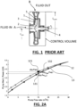
- the present invention concerns a method for identifying the impact of an impeller wear and excessive wear-ring clearance on the whole performance of a centrifugal pump such as shown in figure 1 having a body 1, an impeller 2 with impeller blades 3 and impeller axis 4.
- Centrifugal pumps are working in different hydraulic applications, from clean water to wastewater applications. It transports different kinds of fluid with different properties and densities.
- the different mechanical parts impeller, blades, wear-ring, diffuser ...) that compose a centrifugal pump suffer, and they can wear differently depending on the causes: cavitation, corrosion, abrasion, abnormal usage...; The degradation of those parts generates internal losses and decreases the performance of such pumps.
- the losses can be quantified in terms of flow rate and losses in terms of pump total dynamic head capacity.
- the leakage losses are associated with an excessive wear-ring clearance that is the wear of the blades tips and wear-ring which causes an excessive clearance 5 inside the carter of the pump.
- Such excessive clearance increases the flow rate recirculating between the rotating and stationary parts of the pump stage. Because of such clearance, the pump is rejecting a flow rate quantity lower than what has been stirred inside the pump. The flow rate inside the pump is higher than what can be measured in the discharge line of the pump.
- Friction losses and shock losses are associated with the wear of the impeller and diffuser because they mainly participate in decreasing of the pump head at a same pumped flow due to losses by friction on the walls of the blades 3 and by shock due to the modification of angles of attack of worn blades.
- Friction loss is prominent at high flow rates. In contrast, leakage loss is more present at relatively low flow rates. Shock loss takes place when the liquid flow rate differs from the designed flow rate.
- the objective of the present disclosure is to provide a method to identify the impact of both the impeller wear and the excessive wear-ring clearance on the overall performance of a centrifugal pump having a fluid inlet A, an impeller 2 and a fluid outlet B.
- H The change in H is called the "Head” ⁇ H of the pump; and because H includes the velocity head V 2 2 g and the elevation head Ze at the point of interest, ⁇ H is often called the “total dynamic head”.
- ⁇ H is often abbreviated to simply "H” and is the increase in height of a column of liquid that the pump would create if the static pressure head p ⁇ g and the velocity head V 2 2 g were converted without loss into elevation head Ze their respective locations at the inlet A to and outlet B from the control volume.
- H th 2 ⁇ R 2 2 g ⁇ N 2 + 2 ⁇ R 2 gS 2 ⁇ cos ⁇ 2 sin ⁇ 2 ⁇ N ⁇ q v
- H r H th ⁇ H friction ⁇ H Shock ⁇ H Leakage ⁇ H recirculation ⁇ H diffuser ⁇ H disk
- Pump manufacturers provide pump curve datasheets which are already considering initial losses of a pump due to friction, shock, and leakage inside the pump as manufactured. As known in the art, the pump curves are different from the Euler theoretical head curve. In the present disclosure, the initial status of the pump as in the datasheet becomes the theoretical characteristic of the pump on which calculations are based. The evolution of the pump curve starting from the datasheet corresponds to an evolution of the internal mechanical parts of the pump.
- the present disclosure provides an identification of the impact of the impeller wear and excessive wear-ring clearance on the whole pump performance.
- a purpose of the present disclosure is to detect the evolution of both mechanical parts inside the pump and how they impact the performance and energy consumption of the pump.
- the proposed method is based on a model of efficiency and a method to separate impeller wear and excessive wear-ring clearance based on Mechanical Power versus Flow Rate curves such as in figure 2A which shows an actual pump curve 12 in dotted line and a theoretical or manufacturer curve 13 in solid line and based on Pump Head versus Flow Rate curves such as in figure 2B which shows an actual pump curve 14 in dotted lines and a theoretical or manufacturer curve 15 in solid line.
- Qp Pwp is the projection of the measured power on the theoretical Mechanical Power versus Pump Flow rate curve 13 at point 132 allowing calculate the flow rate that the pump sees internally including the internal recirculation due to wear-ring clearance.
- Pw Qp is the projection of the measured flow rate 121 on the theoretical Mechanical Power versus Pump Flow rate curve 13 and corresponds to the mechanical power that should be given if the pump behaves as given by the pump manufacturer. It should be noted that the actual pump curve 12 is shown for a better understanding of the phenomenon but only the current working point Qp, Pwp is needed for the calculation.
- ⁇ Q is the additional flow rate due to the increasing of the wear-ring clearance compared to initial status of the pump that is provided by the Manufacturer.
- ⁇ Q is the additional flow rate due to the increasing of the wear-ring clearance compared to the initial status of the pump that is provided by the theoretical Pump Head versus Flow rate curve 15.
- All these calculated data may be displayed on a monitoring computer or memorized to provide tracking of the degradation of the pump in order to provide information as per the risk of failure in predictive maintenance programs.
- the method of calculating the wear data may be repeated from time to time to obtain a plurality of measurements of the global efficiency of the pump during its working life.
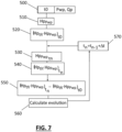
- the program as depicted in figure 8 may also survey an evolution of a pump impeller wear evolution through calculating said impeller wear effect through measuring an initial input pressure p int0 , an actual output pressure p outt0 and an initial pump power Pwp t0 of the pump at a time t0 600 as an initialization.
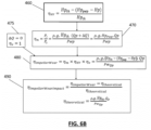
- the calculations of figures 6A and 6B may also be done at each iteration of the two program parts shown in figures 7 and 8 and discussed above embedding the programs of figures 4 and 5 , the measurements and calculation being preferably done in real time during operation of the pump.
- the present disclosure provides means to identify if there is a fault related to impeller wear or wear-ring clearance separately and to identify the impact of each fault on the pump wear and performances.
- the pump curves from the manufacturer are entered in such program in a preliminary step as such theoretical pump curves.
- An identification of an evolution of the wear ring clearance is done by regularly analyzing the measurements (Power, flow rate) and calculating the wear ring clearance effect using the theoretical pump curves and calculating the mechanical efficiency, hydraulic efficiency, and volumetric efficiency to get the global efficiency at different moments of the life of the pump and to compare later values of such efficiencies with older values with the new status of wear-ring clearance.
- the method also provides an identification of the evolution of the impeller wear after deducing the impact of the wear-ring clearance from the theoretical pump curve by analyzing the measurement (Power, Pump head) and the pump curve at flow rate-axis and computing the mechanical efficiency, hydraulic efficiency, and volumetric efficiency to get the global efficiency with the new status of the impeller.
- the method may also comprise comparing of an actual flow rate with at least one customer defined flow rate lower limit and providing a warning signal in case of detection of a flow rate lower than said lower limit, a calculation of the impact of the degradation on the efficiency of said impeller and provision of ageing data comprising flow rate reduction and/or head reduction, a calculation of the impact of such degradation on the energy consumption of the pump.
- a survey method may comprise also a program to create warning signals upon detection of defined wear-ring clearance and/or impeller wear for providing data for predictive maintenance.
- An initialization method may also comprise entering said theoretical Pump mechanical Power versus Flow rate curve 13, said theoretical Head versus Flow rate curve 15 from the pump manufacturer as initial theoretical pump data in a calculation program executing the method of the disclosure.
- the program may be embedded in a control unit of the pump connected to sensors on the pump to get the measurement values or embedded in a remote-control center.
Landscapes
- Engineering & Computer Science (AREA)
- General Engineering & Computer Science (AREA)
- Mechanical Engineering (AREA)
- Physics & Mathematics (AREA)
- General Physics & Mathematics (AREA)
- Data Mining & Analysis (AREA)
- Mathematical Physics (AREA)
- Theoretical Computer Science (AREA)
- Mathematical Analysis (AREA)
- Mathematical Optimization (AREA)
- Pure & Applied Mathematics (AREA)
- Databases & Information Systems (AREA)
- Software Systems (AREA)
- Computational Mathematics (AREA)
- Algebra (AREA)
- Structures Of Non-Positive Displacement Pumps (AREA)
- Control Of Non-Positive-Displacement Pumps (AREA)
Priority Applications (4)
| Application Number | Priority Date | Filing Date | Title |
|---|---|---|---|
| EP22306872.7A EP4386210A1 (de) | 2022-12-14 | 2022-12-14 | Verfahren zur erkennung von laufradverschleiss und übermässigem verschleissringspiel in kreiselpumpen |
| AU2023278053A AU2023278053A1 (en) | 2022-12-14 | 2023-12-06 | Method for identification of impeller wear and excessive wear-ring clearance in centrifugal pumps |
| US18/533,797 US20240200560A1 (en) | 2022-12-14 | 2023-12-08 | Method for identification of impeller wear and excessive wear-ring clearance in centrifugal pumps |
| CN202311718203.XA CN118190374A (zh) | 2022-12-14 | 2023-12-13 | 识别离心泵中叶轮磨损和磨损环间隙过大的方法 |
Applications Claiming Priority (1)
| Application Number | Priority Date | Filing Date | Title |
|---|---|---|---|
| EP22306872.7A EP4386210A1 (de) | 2022-12-14 | 2022-12-14 | Verfahren zur erkennung von laufradverschleiss und übermässigem verschleissringspiel in kreiselpumpen |
Publications (1)
| Publication Number | Publication Date |
|---|---|
| EP4386210A1 true EP4386210A1 (de) | 2024-06-19 |
Family
ID=84602260
Family Applications (1)
| Application Number | Title | Priority Date | Filing Date |
|---|---|---|---|
| EP22306872.7A Pending EP4386210A1 (de) | 2022-12-14 | 2022-12-14 | Verfahren zur erkennung von laufradverschleiss und übermässigem verschleissringspiel in kreiselpumpen |
Country Status (4)
| Country | Link |
|---|---|
| US (1) | US20240200560A1 (de) |
| EP (1) | EP4386210A1 (de) |
| CN (1) | CN118190374A (de) |
| AU (1) | AU2023278053A1 (de) |
Families Citing this family (3)
| Publication number | Priority date | Publication date | Assignee | Title |
|---|---|---|---|---|
| CN119830716B (zh) * | 2024-12-16 | 2025-09-26 | 中国航空综合技术研究所 | 基于性能退化的海水离心泵寿命预测方法及系统 |
| CN119333406B (zh) * | 2024-12-24 | 2025-02-28 | 毅飞泵业(福州)有限公司 | 基于智能水泵数据采集功能的水泵控制系统 |
| CN120868045B (zh) * | 2025-09-23 | 2025-12-12 | 辽宁恒星泵业有限公司 | 一种化工流程泵的自动控制系统及方法 |
Citations (3)
| Publication number | Priority date | Publication date | Assignee | Title |
|---|---|---|---|---|
| GB2313197A (en) * | 1996-05-08 | 1997-11-19 | Advanced Energy Monitor Syst | Measuring pump flow rate |
| JP2003028076A (ja) * | 2001-07-12 | 2003-01-29 | Hitachi Ltd | ポンプ異常診断装置 |
| US20120111114A1 (en) * | 2009-05-20 | 2012-05-10 | Ksb Aktiengesellschaft | Method and Apparatus for Determining an Operating Point of a Work Machine |
-
2022
- 2022-12-14 EP EP22306872.7A patent/EP4386210A1/de active Pending
-
2023
- 2023-12-06 AU AU2023278053A patent/AU2023278053A1/en active Pending
- 2023-12-08 US US18/533,797 patent/US20240200560A1/en active Pending
- 2023-12-13 CN CN202311718203.XA patent/CN118190374A/zh active Pending
Patent Citations (3)
| Publication number | Priority date | Publication date | Assignee | Title |
|---|---|---|---|---|
| GB2313197A (en) * | 1996-05-08 | 1997-11-19 | Advanced Energy Monitor Syst | Measuring pump flow rate |
| JP2003028076A (ja) * | 2001-07-12 | 2003-01-29 | Hitachi Ltd | ポンプ異常診断装置 |
| US20120111114A1 (en) * | 2009-05-20 | 2012-05-10 | Ksb Aktiengesellschaft | Method and Apparatus for Determining an Operating Point of a Work Machine |
Also Published As
| Publication number | Publication date |
|---|---|
| CN118190374A (zh) | 2024-06-14 |
| AU2023278053A1 (en) | 2024-07-04 |
| US20240200560A1 (en) | 2024-06-20 |
Similar Documents
| Publication | Publication Date | Title |
|---|---|---|
| EP4386210A1 (de) | Verfahren zur erkennung von laufradverschleiss und übermässigem verschleissringspiel in kreiselpumpen | |
| EP2505847B1 (de) | Verfahren zum erkennen des verschleisses in einer mit einem frequenzumrichter angetriebenen pumpe | |
| CN105114334B (zh) | 基于计算流体动力学理论的多级离心泵叶轮口环磨损量监测方法 | |
| US20030133808A1 (en) | Centrifugal pump performance degradation detection | |
| EP2505846A1 (de) | Verfahren und Anordnung zur Einschätzung der Flussrate einer Pumpe | |
| Ahonen | Monitoring of centrifugal pump operation by a frequency converter | |
| Papa et al. | Pump energy efficiency field testing and benchmarking in Canada | |
| EP3431951B1 (de) | Anomaliebestimmungsvorrichtung und anomaliebestimmungsverfahren | |
| Arndt et al. | Cavitation erosion in hydroturbines | |
| RU2395723C1 (ru) | Способ эксплуатации насосного агрегата в процессе закачки жидкости в пласт | |
| RU2352822C1 (ru) | Способ эксплуатации насоса в процессе закачки жидкости в пласт | |
| Luc et al. | Performance indicators of irrigation pumping stations: application to drill holes of minor irrigated areas in the Kairouan plains (Tunisia) and impact of malfunction on the price of water | |
| Belardini et al. | Four Quadrant Centrifugal Compressor Performance | |
| De Ojeda et al. | Laser velocimetry measurements in a double volute centrifugal pump | |
| Guo et al. | Three-dimensional flow analysis and improvement of slip factor model for forward-curved blades centrifugal fan | |
| Stopa et al. | Detection of incipient cavitation phenomenon in a centrifugal pump | |
| US11022595B2 (en) | Determining the phase composition of a fluid flow | |
| Bolade et al. | Analysis of Hydraulic Thrusts in Centrifugal Pump to Increase te Bearing Life | |
| Jarrell et al. | Physics-based prognostics for optimizing plant operations | |
| EP4497950A1 (de) | Verfahren zur schätzung der ausgangsdurchflusses einer pumpe | |
| Weidenholzer et al. | Novel Sediment Monitoring Method Based on Structure-Borne Sound Measurement | |
| RU2610637C1 (ru) | Способ определения КПД насоса | |
| US20240004377A1 (en) | A pump monitoring system and method for associating a current operating state of a pump system with one or more fault scenarios | |
| Bozic et al. | Laboratory setup for measurements basic pump system characteristics | |
| Stoffel et al. | Thermodynamic On-Site Measurement of the Efficiency of Centrifugal Water Supply Pumps in the Frame of Condition Orientated Maintenance |
Legal Events
| Date | Code | Title | Description |
|---|---|---|---|
| PUAI | Public reference made under article 153(3) epc to a published international application that has entered the european phase |
Free format text: ORIGINAL CODE: 0009012 |
|
| STAA | Information on the status of an ep patent application or granted ep patent |
Free format text: STATUS: THE APPLICATION HAS BEEN PUBLISHED |
|
| AK | Designated contracting states |
Kind code of ref document: A1 Designated state(s): AL AT BE BG CH CY CZ DE DK EE ES FI FR GB GR HR HU IE IS IT LI LT LU LV MC ME MK MT NL NO PL PT RO RS SE SI SK SM TR |
|
| STAA | Information on the status of an ep patent application or granted ep patent |
Free format text: STATUS: REQUEST FOR EXAMINATION WAS MADE |
|
| 17P | Request for examination filed |
Effective date: 20241118 |
|
| RBV | Designated contracting states (corrected) |
Designated state(s): AL AT BE BG CH CY CZ DE DK EE ES FI FR GB GR HR HU IE IS IT LI LT LU LV MC ME MK MT NL NO PL PT RO RS SE SI SK SM TR |