EP4386247A2 - Tige de forage ou adaptateur avec accouplement à ergot renforcé - Google Patents
Tige de forage ou adaptateur avec accouplement à ergot renforcé Download PDFInfo
- Publication number
- EP4386247A2 EP4386247A2 EP24168119.6A EP24168119A EP4386247A2 EP 4386247 A2 EP4386247 A2 EP 4386247A2 EP 24168119 A EP24168119 A EP 24168119A EP 4386247 A2 EP4386247 A2 EP 4386247A2
- Authority
- EP
- European Patent Office
- Prior art keywords
- component
- threaded
- quotient
- shank
- threaded section
- Prior art date
- Legal status (The legal status is an assumption and is not a legal conclusion. Google has not performed a legal analysis and makes no representation as to the accuracy of the status listed.)
- Pending
Links
Images

Classifications
-
- E—FIXED CONSTRUCTIONS
- E21—EARTH OR ROCK DRILLING; MINING
- E21B—EARTH OR ROCK DRILLING; OBTAINING OIL, GAS, WATER, SOLUBLE OR MELTABLE MATERIALS OR A SLURRY OF MINERALS FROM WELLS
- E21B1/00—Percussion drilling
- E21B1/38—Hammer piston type, i.e. in which the tool bit or anvil is hit by an impulse member
-
- E—FIXED CONSTRUCTIONS
- E21—EARTH OR ROCK DRILLING; MINING
- E21B—EARTH OR ROCK DRILLING; OBTAINING OIL, GAS, WATER, SOLUBLE OR MELTABLE MATERIALS OR A SLURRY OF MINERALS FROM WELLS
- E21B17/00—Drilling rods or pipes; Flexible drill strings; Kellies; Drill collars; Sucker rods; Cables; Casings; Tubings
- E21B17/02—Couplings; joints
- E21B17/04—Couplings; joints between rod or the like and bit or between rod and rod or the like
- E21B17/042—Threaded
-
- E—FIXED CONSTRUCTIONS
- E21—EARTH OR ROCK DRILLING; MINING
- E21B—EARTH OR ROCK DRILLING; OBTAINING OIL, GAS, WATER, SOLUBLE OR MELTABLE MATERIALS OR A SLURRY OF MINERALS FROM WELLS
- E21B17/00—Drilling rods or pipes; Flexible drill strings; Kellies; Drill collars; Sucker rods; Cables; Casings; Tubings
- E21B17/02—Couplings; joints
- E21B17/04—Couplings; joints between rod or the like and bit or between rod and rod or the like
- E21B17/042—Threaded
- E21B17/0426—Threaded with a threaded cylindrical portion, e.g. for percussion rods
-
- F—MECHANICAL ENGINEERING; LIGHTING; HEATING; WEAPONS; BLASTING
- F16—ENGINEERING ELEMENTS AND UNITS; GENERAL MEASURES FOR PRODUCING AND MAINTAINING EFFECTIVE FUNCTIONING OF MACHINES OR INSTALLATIONS; THERMAL INSULATION IN GENERAL
- F16L—PIPES; JOINTS OR FITTINGS FOR PIPES; SUPPORTS FOR PIPES, CABLES OR PROTECTIVE TUBING; MEANS FOR THERMAL INSULATION IN GENERAL
- F16L15/00—Screw-threaded joints; Forms of screw-threads for such joints
- F16L15/06—Screw-threaded joints; Forms of screw-threads for such joints characterised by the shape of the screw-thread
Definitions
- the present invention relates to a drill string component to form part of a drill string having a male spigot coupling end with a threaded section configured to minimise stress at the region of the threads and failure of the coupling.
- Percussion drilling is used to create a long borehole via a plurality of elongate drill string rods coupled together end-to-end by interconnected male and female threaded ends.
- the well-established technique breaks rock by hammering impacts transferred from the rock drill bit, mounted at one end of the drill string, to the rock at the bottom of the borehole.
- the energy required to break the rock is generated by a hydraulically driven piston that contacts the end of the drill string (via a shank adaptor) to create a stress (or shock) wave that propagates through the drill string and ultimately to the base rock level.
- the joint is typically subjected to bending forces during drilling. These bending moments fatigue the coupling and lead to breakage within the threaded portion of the j oint.
- the threaded male spigot that is damaged and determines the operational lifetime of the coupling.
- stresses in the threaded section of the male spigot are typically considerable and it is common for the spigot to fail at the region of the threads. Additionally, stresses at the region of the threads occur also due to the transmission of the compressing shock wave. Accordingly, what is required is a strengthened male threaded coupling that addresses the above problems.
- the objectives are achieved by providing a male coupling at a drill component with a shoulder contact region in which an axial length of a non-threaded shank part of the male spigot coupling has a predetermined minimum value relative to an external diameter of the male spigot at the threaded section.
- an elongate component to form part of a drill string comprising: an elongate length section having a pair of axial ends; a male spigot provided at at least one of the ends and having an externally threaded section and a non-threaded shank positioned axially intermediate the threaded section and the length section; the male spigot projecting axially from an annular side surface of the length section or a radially outward extending shoulder, the threaded section having an outside diameter (Dy) corresponding to a crest of the thread and the non-threaded shank comprises an axial length (Ls) defined between an axially inner end of the threaded section and the side surface; characterised in that: the quotient Ls/Dy is equal to or greater than 0.4.
- Dy corresponds to the diametric distance between the radial positions at the crests (of the helical ridge) on diametrically opposite sides of the threaded section to represent a maximum diameter of the threaded section.
- Dy corresponds to the diametric distance of the axially endmost crest having the largest radius/diameter.
- the quotient Ls/Dy is in the range 0.4 to 1.0.
- the quotient Ls/Dy is in the range 0.45 to 1.0, 0.5 to 1.0, 0.55 to 1.0, 0.6 to 1.0, 0.65 to 1.0, 0.7 to 1.0, 0.75 to 1.0; 0.8 to 1.0 or 0.85 to 1.0.
- the quotient Ls/Dy is in the range 0.4 to 0.8 or 0.5 to 0.8.
- the quotient Ls/Dy may be equal to or greater than 0.45, 0.5, 0.6 or 0.7.
- Axially separating the helical threads from the shoulder contact region of the drill string component via this minimum axial length of the non-threaded shank minimises the magnitude of the bending forces transmitted through the helical thread resultant from lateral deviations in the position of the drill bit during drilling or potentially imperfect hammer strikes. Accordingly, the lifetime of the drill component is enhanced over conventional male couplings in addition to reducing the risk of down-the-hole coupling failures.
- the spigot comprises an axial length (L) defined between an axial endmost surface of the spigot and the side surface of the length section or shoulder, wherein the quotient Ls/L is equal to or greater than 0.25. More preferably, the quotient Ls/L is the range 0.25 to 0.5; 0.3 to 0.5; 0.35 to 0.5; 0.4 to 0.5; 0.45 to 0.5.
- the threaded section is axially separated from the shoulder contact region of the component and hence is configured to better withstand bending moments and accordingly to reduce stress concentrations at the helical thread.
- the axially inner end of the threaded section is defined as the axial position at which a radial position of the crest or a root of the thread corresponds to the radial position of an external surface of the non-threaded shank.
- the shank comprises a transitional region positioned adjacent the annular side surface wherein a cross sectional profile at the transition region in a plane extending in a longitudinal axis of the component is curved such that a cross sectional area of the shank increases axially towards the annular side surface.
- the curvature of the transition region axially closest to the side surface comprises a first radius of curvature that is less than a second radius of curvature of the outer surface at the transition region axially closest the threaded section, the outside diameter of the transition region over the first and second radii of curvature increasing in a direction from the threaded section to the side surface.
- the axial junction between the shoulder region of the component and the spigot (and in particular the non-threaded shank) is reinforced against bending moments to reduce stress concentration and the risk of failure of the coupling under load.
- Reference to ' curvature' encompasses a smooth or gradual change in the surface profile and also a plurality of sequential linear increases in the diameter from the non-threaded shank to the shoulder that collectively may be regarded as a ' curved' shape profile.
- the drill string component comprises a shoulder projecting radially from a main length or general length section of the component such that outside diameter of the shoulder is greater than an outside diameter of the length section and/or the male spigot.
- the shoulder and in particular the annular side surface may be formed by an axial end of the length section of the component or the axial side of the radially extending shoulder.
- a cross sectional profile of the outer surface of the transition region between the non-threaded shank and the annular end surface in a plane of the longitudinal axis of the component comprises a segment of an ellipse.
- the segment is substantially one quarter of a perimeter of an ellipse.
- a diameter (Ds) of the shank is approximately equal to or less than a diameter of (Dm) of the length section.
- Ds is less than or approximately equal to Dy.
- Ls is less than an axial length Lt of the threaded section.
- a drill string comprising: a component as claimed herein; a plurality of drill rods and a drill bit provided at one axial end of the drill string.
- the drill string component may comprise anyone of the following: a drill rod; a drill tube; a shank adaptor; a drill bit.
- shank adaptor being a drill string component to form part of a drill string. It will be appreciated that the subject invention is applicable to any elongate component having a shoulder contact male spigot end adapted to form a coupling joint with a threaded female sleeve of an adjacent component of the drill string. Accordingly, the subject invention may be applied to a drill rod, drill tubing, a shank, a shank adaptor, a drill bit, a shaft or adaptor mounted at the driving end of the drill string or at the bit end of the drill string.
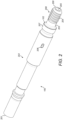
- a drill string comprises an elongate shank adaptor 100 coupled axially to an endmost drill rod 101 via a threaded coupling 104 formed by a male threaded end of the shank adaptor 100 and a female threaded end of the drill rod 101.
- Both drill string components 100, 101 are coupled via 'shoulder contact' in which an annular side surface 102 of the male coupling of adaptor 100 is engaged in touching contact with a corresponding annular side surface 103 of the female sleeve of the drill rod 101.
- the shank adaptor 100 comprises a main length section 202 having a first end 200 and a second end 201 and is configured for mounting at the driving end of the drill string adjacent the percussive hammer via second end 201.
- a flushing hole 206 is formed within main length section 202 to allow the introduction of a flushing fluid into a central bore 205 extending axially through the axially forward length part of adaptor 100 between flushing hole 206 and first end 200.
- Main length section 202 is terminated towards first end 200 by an annular shoulder 207 that projects radially from a male spigot 208 comprising an external diameter being less than a corresponding external diameter of shoulder 207 and main length section 202.
- the annular side surface 102 is provided at the axial junction between spigot 208 and shoulder 207 to provide the shoulder contact surface for abutment against the annular side surface 103 of the threaded female coupling.
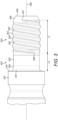
- Spigot 208 is divided axially into a threaded section 204 extending axially towards first end 200 and a non-threaded shank 203 positioned axially intermediate threaded section 204 and shoulder 207.
- the non-threaded shank 203 comprises a generally cylindrical region 302 positioned axially closest to threaded section 204 and a transition region that forms an axial junction with the annular side surface 102 of shoulder 207.
- An external diameter of the non-threaded shank 203 at the transition region increases from the cylindrical region 302 to a first curved region 300 having a first radius of curvature and a second curved region 301 having a second radius of curvature being less than the first radius of curvature of region 300.
- a curvature of the non-threaded shank at the transition region 300, 301 comprises an elliptical shape profile. This curvature, at the transition region 300, 301 between non-threaded shank 203 and shoulder 207 is advantageous to strengthen the spigot 208 against bending forces encountered by the drill string during drilling.
- Threaded section 204 comprises a single-start thread-form having a single ridge formed by helical turns extending axially between a first thread end 307 (positioned towards adaptor first end 200) and a second thread end 306 terminating at the non-threaded shank 203.
- a helically wound ridge accordingly comprises helical turns having a crests 303 and axially intermediate roots 304.
- the roots 304 and crest 303 are separated by flanks 305 being curved and extending generally transverse to a longitudinal axis 309 extending through shank adaptor 101.
- a depth of the thread at first end 307 diminishes along the circumferential path of crest 303 for a portion of an endmost helical turn axially closest to adaptor first end 200. Accordingly, thread first end 307 terminates as a smooth radial transition into a generally conical end region 307 of spigot 208 that is in turn terminated by an annular end surface at adaptor first end 200. Similarly, thread second end 306 is formed as a gradual radial transition into the non-threaded shank region 302.
- the thread depth within the endmost helical turn at both thread end 306, 307 diminishes as the external diameter of the crest 303 within the final axial portion of each endmost helical turn decreases towards the external diameter of the non-threaded shank 203 and conical end section 308, respectively.
- the gradual reduction in the external diameter of the crest 303 at the thread ends 307, 306 is advantageous to reduce stress concentrations at the threaded section 204 so as to contribute to the increased strength of the present male spigot end 208.
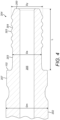
- the non-threaded shank 203 comprises an axial length Ls defined as the axial distance between annular side surface 102 and the axially innermost second end 306 of threaded section 204.
- the thread second end 306 is defined as the axial region at which the crest 303 diminishes to an external diameter of the non-threaded shank 203.
- This axial position is accordingly defined as the region where a cross sectional shape profile of the male spigot 208 is circular corresponding to the cylindrical non-threaded shank 203 in contrast to the non-circular cross sectional shape profile of the threaded section 204.
- an axial length Lt of the threaded section 204 is defined as the axial distance between the thread first and second ends 307, 306.
- the thread first end 307 is defined as the axial position where the cross sectional shape profile of the conical section 308 becomes circular.
- Male spigot 208 also comprises a main axial length L defined as the axial distance between annular side surface 102 and adaptor first end 200.
- an external diameter Ds of the non-threaded shank at the cylindrical region 302 is less than the corresponding external diameter Dm of the main length section 202 and a corresponding external diameter at the annular shoulder 207.
- the diameter Ds is also less than an external diameter Dy of the threaded section 204 corresponding to the radial position of the peak of crest 303 at each helical turn.
- Dy is uniform over the axial length Lt of threaded section 204 such that the threaded is provided on a generally cylindrical spigot 208.
- the subject invention is equally suitable for conical spigots 208 having in particular a conical threaded section 204.
- the quotient Ls/Dy is in a range 0.4 to 1.0 and according to the specific implementation is 0.5 to 0.7. Additionally, this strengthening of the spigot 208 may be expressed as the quotient Ls/L being in the range 0.25 to 0.5 and in particular 0.28 to 0.32. Accordingly, Lt is greater than Ls.
- Enhancing the axial length Ls of the non-threaded shank 103 is advantageous to separate axially the threaded section 204 from annular side surface 102 that has been found through simulation investigations to minimise the stress at the helical turns and in particular the crests 303, roots 304 and flanks 305 for shoulder contact threaded couplings. Accordingly, the risk of failure of the coupling joint is minimised and the operational lifetime of the drill string components enhanced.
Landscapes
- Engineering & Computer Science (AREA)
- Geology (AREA)
- Life Sciences & Earth Sciences (AREA)
- Mining & Mineral Resources (AREA)
- Mechanical Engineering (AREA)
- Physics & Mathematics (AREA)
- Environmental & Geological Engineering (AREA)
- Fluid Mechanics (AREA)
- General Life Sciences & Earth Sciences (AREA)
- Geochemistry & Mineralogy (AREA)
- General Engineering & Computer Science (AREA)
- Earth Drilling (AREA)
- Drilling Tools (AREA)
Priority Applications (1)
| Application Number | Priority Date | Filing Date | Title |
|---|---|---|---|
| EP24168119.6A EP4386247A3 (fr) | 2015-05-22 | 2015-05-22 | Tige de forage ou adaptateur avec accouplement à ergot renforcé |
Applications Claiming Priority (2)
| Application Number | Priority Date | Filing Date | Title |
|---|---|---|---|
| EP24168119.6A EP4386247A3 (fr) | 2015-05-22 | 2015-05-22 | Tige de forage ou adaptateur avec accouplement à ergot renforcé |
| EP15168921.3A EP3095954B1 (fr) | 2015-05-22 | 2015-05-22 | Tige de forage ou adaptateur de couplage avec un embout renforcé |
Related Parent Applications (2)
| Application Number | Title | Priority Date | Filing Date |
|---|---|---|---|
| EP15168921.3A Division EP3095954B1 (fr) | 2015-05-22 | 2015-05-22 | Tige de forage ou adaptateur de couplage avec un embout renforcé |
| EP15168921.3A Division-Into EP3095954B1 (fr) | 2015-05-22 | 2015-05-22 | Tige de forage ou adaptateur de couplage avec un embout renforcé |
Publications (2)
| Publication Number | Publication Date |
|---|---|
| EP4386247A2 true EP4386247A2 (fr) | 2024-06-19 |
| EP4386247A3 EP4386247A3 (fr) | 2024-09-25 |
Family
ID=53191559
Family Applications (3)
| Application Number | Title | Priority Date | Filing Date |
|---|---|---|---|
| EP24168119.6A Pending EP4386247A3 (fr) | 2015-05-22 | 2015-05-22 | Tige de forage ou adaptateur avec accouplement à ergot renforcé |
| EP15168921.3A Revoked EP3095954B1 (fr) | 2015-05-22 | 2015-05-22 | Tige de forage ou adaptateur de couplage avec un embout renforcé |
| EP16725462.2A Active EP3298229B1 (fr) | 2015-05-22 | 2016-05-19 | Tige de forage ou adaptateur de couplage avec un embout renforcé |
Family Applications After (2)
| Application Number | Title | Priority Date | Filing Date |
|---|---|---|---|
| EP15168921.3A Revoked EP3095954B1 (fr) | 2015-05-22 | 2015-05-22 | Tige de forage ou adaptateur de couplage avec un embout renforcé |
| EP16725462.2A Active EP3298229B1 (fr) | 2015-05-22 | 2016-05-19 | Tige de forage ou adaptateur de couplage avec un embout renforcé |
Country Status (14)
| Country | Link |
|---|---|
| US (1) | US11162619B2 (fr) |
| EP (3) | EP4386247A3 (fr) |
| CN (1) | CN107683363B (fr) |
| AU (1) | AU2016266604B2 (fr) |
| BR (1) | BR112017024932B1 (fr) |
| CA (1) | CA2986624C (fr) |
| CL (1) | CL2017002940A1 (fr) |
| MX (1) | MX389505B (fr) |
| PE (1) | PE20180718A1 (fr) |
| PL (2) | PL3095954T3 (fr) |
| PT (1) | PT3298229T (fr) |
| RU (1) | RU2713548C2 (fr) |
| WO (1) | WO2016188862A1 (fr) |
| ZA (1) | ZA201707459B (fr) |
Families Citing this family (13)
| Publication number | Priority date | Publication date | Assignee | Title |
|---|---|---|---|---|
| EP2845991B1 (fr) | 2013-09-09 | 2015-11-18 | Sandvik Intellectual Property AB | Tiges de train de forage à couplage à ergot renforcé |
| PL3095954T3 (pl) | 2015-05-22 | 2024-08-05 | Sandvik Intellectual Property Ab | Żerdź wiertnicza lub łącznik ze wzmocnionym złączem czopowym |
| US20180100356A1 (en) * | 2016-10-10 | 2018-04-12 | Padley & Venables Limited | Drill Rod |
| EP3536894B1 (fr) | 2018-03-09 | 2020-10-14 | Sandvik Mining and Construction Tools AB | Raccord permettant de raccorder des éléments tubulaires de fond de trou |
| EP3663506B1 (fr) | 2018-12-03 | 2022-11-16 | Sandvik Mining and Construction G.m.b.H. | Train de tiges, couplage fileté et adaptateur de tige pour forage rotatif |
| PL3712374T3 (pl) * | 2019-03-18 | 2023-01-16 | Sandvik Mining And Construction Tools Ab | Żerdź przewodu wiertniczego |
| PE20220853A1 (es) * | 2019-10-11 | 2022-05-24 | Sandvik Mining And Construction Tools Ab | Ensamblaje de perforacion protegido con hombro |
| PL3879065T3 (pl) | 2020-03-11 | 2023-03-13 | Sandvik Mining And Construction Tools Ab | Eliptyczna konstrukcja luzu gwintu zewnętrznego |
| EP3933165A1 (fr) * | 2020-06-30 | 2022-01-05 | Sandvik Mining and Construction Tools AB | Dégagement de filetage |
| PL3971385T3 (pl) | 2020-09-17 | 2023-07-31 | Sandvik Mining And Construction Tools Ab | Konstrukcja połączenia kolumny wiertniczej |
| EP4047178B1 (fr) * | 2021-02-17 | 2023-09-13 | Sandvik Mining and Construction Tools AB | Conception elliptique pour tiges hexagonales |
| EP4047179B1 (fr) * | 2021-02-17 | 2023-09-13 | Sandvik Mining and Construction Tools AB | Conception elliptique pour adaptateurs de queue |
| EP4660418A1 (fr) * | 2024-06-04 | 2025-12-10 | Sandvik Mining and Construction Tools AB | Protection d'épaule pour composant de foret allongé |
Citations (4)
| Publication number | Priority date | Publication date | Assignee | Title |
|---|---|---|---|---|
| US4968068A (en) | 1988-07-08 | 1990-11-06 | Sandvik Ab | Thread coupling for drill string members |
| EP1232321A1 (fr) | 1999-11-26 | 2002-08-21 | Sandvik AB (publ) | Joint filete a partie male et partie femelle |
| EP1259703A1 (fr) | 2000-03-02 | 2002-11-27 | Sandvik Aktiebolag | Joint filete et element de perforation de roches |
| EP2845993A1 (fr) | 2013-09-09 | 2015-03-11 | Sandvik Intellectual Property AB | Couplage de tiges de forage à transmission d'énergie efficace |
Family Cites Families (19)
| Publication number | Priority date | Publication date | Assignee | Title |
|---|---|---|---|---|
| US1926925A (en) | 1931-04-07 | 1933-09-12 | Gulf Res & Dev Corp | Pin, bolt, and other connecting device |
| US3537738A (en) | 1968-04-15 | 1970-11-03 | Sandvikens Jernverks Ab | Drill rod for long hole drilling in the ground |
| US4548431A (en) * | 1981-12-17 | 1985-10-22 | Hughes Tool Company - Usa | Tool joint with internal/external make-up shoulders |
| US5169183A (en) * | 1987-05-12 | 1992-12-08 | Diamant Boart Stratabit S.A. | Threaded joint for drill rod elements |
| USH1329H (en) * | 1992-04-28 | 1994-07-05 | Exxon Production Research Company | Drill collar connections |
| SE505073C2 (sv) | 1994-07-19 | 1997-06-23 | Sandvik Ab | Gängförband för slående borrning |
| US5492375A (en) * | 1994-07-21 | 1996-02-20 | Grant Tfw, Inc. | Drill pipe with improved connectors |
| CA2303710C (fr) | 1997-01-06 | 2005-11-08 | Boart Longyear Inc. | Systeme de forage de trous droits |
| AUPO445897A0 (en) * | 1997-01-06 | 1997-01-30 | Boart Longyear Inc. | Straight hole drilling system |
| GB2340148B (en) | 1998-07-30 | 2002-12-31 | Boart Longyear Ltd | Tube rod |
| SE515517C2 (sv) | 1998-09-28 | 2001-08-20 | Uniroc Ab | Gängförband för borrsträng för slående bergborrning |
| US6164392A (en) | 1999-04-26 | 2000-12-26 | Sandvik Ab | Percussive drilling apparatus |
| EP2019904A1 (fr) | 2006-05-17 | 2009-02-04 | Sandvik Intellectual Property AB | Outil de forage de roches, tige de forage et manchon de couplage |
| US20100018699A1 (en) * | 2007-03-21 | 2010-01-28 | Hall David R | Low Stress Threadform with a Non-conic Section Curve |
| SE530158C2 (sv) * | 2007-06-05 | 2008-03-11 | Sandvik Intellectual Property | Bergborrutrustning samt hon- och handelar därtill |
| JP5523373B2 (ja) | 2011-02-18 | 2014-06-18 | 三菱マテリアル株式会社 | 掘削用中空鋼ロッドとその製造方法 |
| EP2845991B1 (fr) * | 2013-09-09 | 2015-11-18 | Sandvik Intellectual Property AB | Tiges de train de forage à couplage à ergot renforcé |
| EP2845992B1 (fr) | 2013-09-09 | 2016-01-13 | Sandvik Intellectual Property AB | Train de tiges de forage avec couplage résistant à la flexion |
| PL3095954T3 (pl) | 2015-05-22 | 2024-08-05 | Sandvik Intellectual Property Ab | Żerdź wiertnicza lub łącznik ze wzmocnionym złączem czopowym |
-
2015
- 2015-05-22 PL PL15168921.3T patent/PL3095954T3/pl unknown
- 2015-05-22 EP EP24168119.6A patent/EP4386247A3/fr active Pending
- 2015-05-22 EP EP15168921.3A patent/EP3095954B1/fr not_active Revoked
-
2016
- 2016-05-19 CA CA2986624A patent/CA2986624C/fr active Active
- 2016-05-19 RU RU2017144031A patent/RU2713548C2/ru active
- 2016-05-19 BR BR112017024932-4A patent/BR112017024932B1/pt active IP Right Grant
- 2016-05-19 AU AU2016266604A patent/AU2016266604B2/en active Active
- 2016-05-19 PL PL16725462T patent/PL3298229T3/pl unknown
- 2016-05-19 WO PCT/EP2016/061300 patent/WO2016188862A1/fr not_active Ceased
- 2016-05-19 PT PT167254622T patent/PT3298229T/pt unknown
- 2016-05-19 CN CN201680029400.2A patent/CN107683363B/zh active Active
- 2016-05-19 PE PE2017002428A patent/PE20180718A1/es unknown
- 2016-05-19 MX MX2017014879A patent/MX389505B/es unknown
- 2016-05-19 EP EP16725462.2A patent/EP3298229B1/fr active Active
- 2016-05-19 US US15/576,113 patent/US11162619B2/en active Active
-
2017
- 2017-11-03 ZA ZA2017/07459A patent/ZA201707459B/en unknown
- 2017-11-20 CL CL2017002940A patent/CL2017002940A1/es unknown
Patent Citations (4)
| Publication number | Priority date | Publication date | Assignee | Title |
|---|---|---|---|---|
| US4968068A (en) | 1988-07-08 | 1990-11-06 | Sandvik Ab | Thread coupling for drill string members |
| EP1232321A1 (fr) | 1999-11-26 | 2002-08-21 | Sandvik AB (publ) | Joint filete a partie male et partie femelle |
| EP1259703A1 (fr) | 2000-03-02 | 2002-11-27 | Sandvik Aktiebolag | Joint filete et element de perforation de roches |
| EP2845993A1 (fr) | 2013-09-09 | 2015-03-11 | Sandvik Intellectual Property AB | Couplage de tiges de forage à transmission d'énergie efficace |
Also Published As
| Publication number | Publication date |
|---|---|
| ZA201707459B (en) | 2021-05-26 |
| MX389505B (es) | 2025-03-20 |
| CA2986624A1 (fr) | 2016-12-01 |
| EP3095954A1 (fr) | 2016-11-23 |
| BR112017024932B1 (pt) | 2023-02-28 |
| US20180135782A1 (en) | 2018-05-17 |
| BR112017024932A2 (pt) | 2018-07-31 |
| CN107683363B (zh) | 2024-07-12 |
| CA2986624C (fr) | 2023-04-25 |
| RU2017144031A3 (fr) | 2019-08-06 |
| US11162619B2 (en) | 2021-11-02 |
| AU2016266604B2 (en) | 2020-09-10 |
| AU2016266604A1 (en) | 2017-12-07 |
| CL2017002940A1 (es) | 2018-03-16 |
| PL3298229T3 (pl) | 2021-02-08 |
| WO2016188862A1 (fr) | 2016-12-01 |
| RU2713548C2 (ru) | 2020-02-05 |
| EP3298229B1 (fr) | 2020-10-14 |
| EP4386247A3 (fr) | 2024-09-25 |
| EP3095954C0 (fr) | 2024-05-15 |
| PL3095954T3 (pl) | 2024-08-05 |
| PE20180718A1 (es) | 2018-04-26 |
| RU2017144031A (ru) | 2019-06-24 |
| EP3095954B1 (fr) | 2024-05-15 |
| MX2017014879A (es) | 2018-04-20 |
| PT3298229T (pt) | 2020-11-19 |
| EP3298229A1 (fr) | 2018-03-28 |
| CN107683363A (zh) | 2018-02-09 |
Similar Documents
| Publication | Publication Date | Title |
|---|---|---|
| EP3095954B1 (fr) | Tige de forage ou adaptateur de couplage avec un embout renforcé | |
| EP2845992B1 (fr) | Train de tiges de forage avec couplage résistant à la flexion | |
| EP2845991B1 (fr) | Tiges de train de forage à couplage à ergot renforcé | |
| EP3298228B1 (fr) | Extrémité de couplage filetée pour composant de train de tiges de percussion | |
| US20170321496A1 (en) | Drill string rod with guidance shoulder | |
| EP3819458B1 (fr) | Couplage femelle de train de forage à percussion renforcé | |
| JP2024507341A (ja) | シャンクアダプタの楕円設計 | |
| EP3663506B1 (fr) | Train de tiges, couplage fileté et adaptateur de tige pour forage rotatif |
Legal Events
| Date | Code | Title | Description |
|---|---|---|---|
| PUAI | Public reference made under article 153(3) epc to a published international application that has entered the european phase |
Free format text: ORIGINAL CODE: 0009012 |
|
| STAA | Information on the status of an ep patent application or granted ep patent |
Free format text: STATUS: THE APPLICATION HAS BEEN PUBLISHED |
|
| AC | Divisional application: reference to earlier application |
Ref document number: 3095954 Country of ref document: EP Kind code of ref document: P |
|
| AK | Designated contracting states |
Kind code of ref document: A2 Designated state(s): AL AT BE BG CH CY CZ DE DK EE ES FI FR GB GR HR HU IE IS IT LI LT LU LV MC MK MT NL NO PL PT RO RS SE SI SK SM TR |
|
| REG | Reference to a national code |
Ref country code: DE Ref legal event code: R079 Free format text: PREVIOUS MAIN CLASS: F16L0015060000 Ipc: E21B0017042000 |
|
| PUAL | Search report despatched |
Free format text: ORIGINAL CODE: 0009013 |
|
| AK | Designated contracting states |
Kind code of ref document: A3 Designated state(s): AL AT BE BG CH CY CZ DE DK EE ES FI FR GB GR HR HU IE IS IT LI LT LU LV MC MK MT NL NO PL PT RO RS SE SI SK SM TR |
|
| RIC1 | Information provided on ipc code assigned before grant |
Ipc: F16L 15/06 20060101ALI20240820BHEP Ipc: E21B 17/042 20060101AFI20240820BHEP |
|
| STAA | Information on the status of an ep patent application or granted ep patent |
Free format text: STATUS: REQUEST FOR EXAMINATION WAS MADE |
|
| 17P | Request for examination filed |
Effective date: 20250325 |
|
| STAA | Information on the status of an ep patent application or granted ep patent |
Free format text: STATUS: EXAMINATION IS IN PROGRESS |
|
| 17Q | First examination report despatched |
Effective date: 20260114 |