EP4386280A1 - Circuit de réfrigération avec stockage thermique - Google Patents
Circuit de réfrigération avec stockage thermique Download PDFInfo
- Publication number
- EP4386280A1 EP4386280A1 EP23217289.0A EP23217289A EP4386280A1 EP 4386280 A1 EP4386280 A1 EP 4386280A1 EP 23217289 A EP23217289 A EP 23217289A EP 4386280 A1 EP4386280 A1 EP 4386280A1
- Authority
- EP
- European Patent Office
- Prior art keywords
- outlet
- thermal battery
- inlet
- refrigeration circuit
- cooler
- Prior art date
- Legal status (The legal status is an assumption and is not a legal conclusion. Google has not performed a legal analysis and makes no representation as to the accuracy of the status listed.)
- Pending
Links
Images



Classifications
-
- F—MECHANICAL ENGINEERING; LIGHTING; HEATING; WEAPONS; BLASTING
- F25—REFRIGERATION OR COOLING; COMBINED HEATING AND REFRIGERATION SYSTEMS; HEAT PUMP SYSTEMS; MANUFACTURE OR STORAGE OF ICE; LIQUEFACTION SOLIDIFICATION OF GASES
- F25B—REFRIGERATION MACHINES, PLANTS OR SYSTEMS; COMBINED HEATING AND REFRIGERATION SYSTEMS; HEAT PUMP SYSTEMS
- F25B31/00—Compressor arrangements
-
- F—MECHANICAL ENGINEERING; LIGHTING; HEATING; WEAPONS; BLASTING
- F25—REFRIGERATION OR COOLING; COMBINED HEATING AND REFRIGERATION SYSTEMS; HEAT PUMP SYSTEMS; MANUFACTURE OR STORAGE OF ICE; LIQUEFACTION SOLIDIFICATION OF GASES
- F25B—REFRIGERATION MACHINES, PLANTS OR SYSTEMS; COMBINED HEATING AND REFRIGERATION SYSTEMS; HEAT PUMP SYSTEMS
- F25B41/00—Fluid-circulation arrangements
- F25B41/20—Disposition of valves, e.g. of on-off valves or flow control valves
-
- F—MECHANICAL ENGINEERING; LIGHTING; HEATING; WEAPONS; BLASTING
- F25—REFRIGERATION OR COOLING; COMBINED HEATING AND REFRIGERATION SYSTEMS; HEAT PUMP SYSTEMS; MANUFACTURE OR STORAGE OF ICE; LIQUEFACTION SOLIDIFICATION OF GASES
- F25B—REFRIGERATION MACHINES, PLANTS OR SYSTEMS; COMBINED HEATING AND REFRIGERATION SYSTEMS; HEAT PUMP SYSTEMS
- F25B41/00—Fluid-circulation arrangements
- F25B41/20—Disposition of valves, e.g. of on-off valves or flow control valves
- F25B41/26—Disposition of valves, e.g. of on-off valves or flow control valves of fluid flow reversing valves
-
- F—MECHANICAL ENGINEERING; LIGHTING; HEATING; WEAPONS; BLASTING
- F25—REFRIGERATION OR COOLING; COMBINED HEATING AND REFRIGERATION SYSTEMS; HEAT PUMP SYSTEMS; MANUFACTURE OR STORAGE OF ICE; LIQUEFACTION SOLIDIFICATION OF GASES
- F25B—REFRIGERATION MACHINES, PLANTS OR SYSTEMS; COMBINED HEATING AND REFRIGERATION SYSTEMS; HEAT PUMP SYSTEMS
- F25B41/00—Fluid-circulation arrangements
- F25B41/40—Fluid line arrangements
-
- F—MECHANICAL ENGINEERING; LIGHTING; HEATING; WEAPONS; BLASTING
- F25—REFRIGERATION OR COOLING; COMBINED HEATING AND REFRIGERATION SYSTEMS; HEAT PUMP SYSTEMS; MANUFACTURE OR STORAGE OF ICE; LIQUEFACTION SOLIDIFICATION OF GASES
- F25B—REFRIGERATION MACHINES, PLANTS OR SYSTEMS; COMBINED HEATING AND REFRIGERATION SYSTEMS; HEAT PUMP SYSTEMS
- F25B49/00—Arrangement or mounting of control or safety devices
- F25B49/02—Arrangement or mounting of control or safety devices for compression type machines, plants or systems
-
- F—MECHANICAL ENGINEERING; LIGHTING; HEATING; WEAPONS; BLASTING
- F25—REFRIGERATION OR COOLING; COMBINED HEATING AND REFRIGERATION SYSTEMS; HEAT PUMP SYSTEMS; MANUFACTURE OR STORAGE OF ICE; LIQUEFACTION SOLIDIFICATION OF GASES
- F25B—REFRIGERATION MACHINES, PLANTS OR SYSTEMS; COMBINED HEATING AND REFRIGERATION SYSTEMS; HEAT PUMP SYSTEMS
- F25B9/00—Compression machines, plants or systems, in which the refrigerant is air or other gas of low boiling point
- F25B9/002—Compression machines, plants or systems, in which the refrigerant is air or other gas of low boiling point characterised by the refrigerant
- F25B9/008—Compression machines, plants or systems, in which the refrigerant is air or other gas of low boiling point characterised by the refrigerant the refrigerant being carbon dioxide
-
- F—MECHANICAL ENGINEERING; LIGHTING; HEATING; WEAPONS; BLASTING
- F25—REFRIGERATION OR COOLING; COMBINED HEATING AND REFRIGERATION SYSTEMS; HEAT PUMP SYSTEMS; MANUFACTURE OR STORAGE OF ICE; LIQUEFACTION SOLIDIFICATION OF GASES
- F25B—REFRIGERATION MACHINES, PLANTS OR SYSTEMS; COMBINED HEATING AND REFRIGERATION SYSTEMS; HEAT PUMP SYSTEMS
- F25B2400/00—Component parts or details not otherwise provided for in this subclass
- F25B2400/05—Compression system with heat exchange between particular parts of the system
- F25B2400/051—Compression system with heat exchange between particular parts of the system between the accumulator and another part of the cycle
-
- F—MECHANICAL ENGINEERING; LIGHTING; HEATING; WEAPONS; BLASTING
- F25—REFRIGERATION OR COOLING; COMBINED HEATING AND REFRIGERATION SYSTEMS; HEAT PUMP SYSTEMS; MANUFACTURE OR STORAGE OF ICE; LIQUEFACTION SOLIDIFICATION OF GASES
- F25B—REFRIGERATION MACHINES, PLANTS OR SYSTEMS; COMBINED HEATING AND REFRIGERATION SYSTEMS; HEAT PUMP SYSTEMS
- F25B2400/00—Component parts or details not otherwise provided for in this subclass
- F25B2400/05—Compression system with heat exchange between particular parts of the system
- F25B2400/053—Compression system with heat exchange between particular parts of the system between the storage receiver and another part of the system
-
- F—MECHANICAL ENGINEERING; LIGHTING; HEATING; WEAPONS; BLASTING
- F25—REFRIGERATION OR COOLING; COMBINED HEATING AND REFRIGERATION SYSTEMS; HEAT PUMP SYSTEMS; MANUFACTURE OR STORAGE OF ICE; LIQUEFACTION SOLIDIFICATION OF GASES
- F25B—REFRIGERATION MACHINES, PLANTS OR SYSTEMS; COMBINED HEATING AND REFRIGERATION SYSTEMS; HEAT PUMP SYSTEMS
- F25B2400/00—Component parts or details not otherwise provided for in this subclass
- F25B2400/05—Compression system with heat exchange between particular parts of the system
- F25B2400/054—Compression system with heat exchange between particular parts of the system between the suction tube of the compressor and another part of the cycle
-
- F—MECHANICAL ENGINEERING; LIGHTING; HEATING; WEAPONS; BLASTING
- F25—REFRIGERATION OR COOLING; COMBINED HEATING AND REFRIGERATION SYSTEMS; HEAT PUMP SYSTEMS; MANUFACTURE OR STORAGE OF ICE; LIQUEFACTION SOLIDIFICATION OF GASES
- F25B—REFRIGERATION MACHINES, PLANTS OR SYSTEMS; COMBINED HEATING AND REFRIGERATION SYSTEMS; HEAT PUMP SYSTEMS
- F25B2400/00—Component parts or details not otherwise provided for in this subclass
- F25B2400/13—Economisers
-
- F—MECHANICAL ENGINEERING; LIGHTING; HEATING; WEAPONS; BLASTING
- F25—REFRIGERATION OR COOLING; COMBINED HEATING AND REFRIGERATION SYSTEMS; HEAT PUMP SYSTEMS; MANUFACTURE OR STORAGE OF ICE; LIQUEFACTION SOLIDIFICATION OF GASES
- F25B—REFRIGERATION MACHINES, PLANTS OR SYSTEMS; COMBINED HEATING AND REFRIGERATION SYSTEMS; HEAT PUMP SYSTEMS
- F25B2400/00—Component parts or details not otherwise provided for in this subclass
- F25B2400/23—Separators
-
- F—MECHANICAL ENGINEERING; LIGHTING; HEATING; WEAPONS; BLASTING
- F25—REFRIGERATION OR COOLING; COMBINED HEATING AND REFRIGERATION SYSTEMS; HEAT PUMP SYSTEMS; MANUFACTURE OR STORAGE OF ICE; LIQUEFACTION SOLIDIFICATION OF GASES
- F25B—REFRIGERATION MACHINES, PLANTS OR SYSTEMS; COMBINED HEATING AND REFRIGERATION SYSTEMS; HEAT PUMP SYSTEMS
- F25B2400/00—Component parts or details not otherwise provided for in this subclass
- F25B2400/24—Thermal storage element
-
- F—MECHANICAL ENGINEERING; LIGHTING; HEATING; WEAPONS; BLASTING
- F25—REFRIGERATION OR COOLING; COMBINED HEATING AND REFRIGERATION SYSTEMS; HEAT PUMP SYSTEMS; MANUFACTURE OR STORAGE OF ICE; LIQUEFACTION SOLIDIFICATION OF GASES
- F25B—REFRIGERATION MACHINES, PLANTS OR SYSTEMS; COMBINED HEATING AND REFRIGERATION SYSTEMS; HEAT PUMP SYSTEMS
- F25B2700/00—Sensing or detecting of parameters; Sensors therefor
- F25B2700/15—Power, e.g. by voltage or current
Definitions
- This invention relates to the field of refrigeration circuits, and more particularly, an improved, reliable, and power-efficient refrigeration circuit.
- Existing refrigeration circuits generally have refrigeration installations operating in dry expansion with superheat, where superheat section in the evaporators may have significantly lower heat transfer efficiency.
- compressors of existing refrigeration circuits may be needed to be operated in direct expansion mode to protect the compressor from liquid refrigerant which may harm the bearings of the compressors.
- carbon dioxide (CO 2 )-based refrigeration systems may operate less efficiently in summer or hot ambient conditions due to the thermodynamics of CO 2 . As a result, high exit temperature at the outlet of the gas-cooler in the refrigeration circuit may result in more flash vapor, thereby requiring more compressors to run the refrigeration circuit.
- a refrigeration circuit comprising a gas-cooler comprising an inlet and an outlet, and a compressor unit comprising one or more compressor, wherein an outlet of the compressor unit is fluidically connected to the inlet of the gas-cooler.
- the refrigeration circuit further comprises one or more evaporators, each comprising an inlet, and an outlet, wherein the outlet of the one or more evaporators is fluidically coupled to the inlet of the compressor unit.
- the refrigeration circuit further comprises a flash tank fluidically connected between one or more of the gas-cooler and the compressor unit, and the one or more evaporators and the compressor unit. Further, the refrigeration circuit comprises one or more thermal battery fluidically coupled to the gas-cooler, the flash tank, the compressor unit, and the one or more evaporators.
- the circuit comprises a controller operatively coupled to one or more components of the refrigeration circuit, wherein the controller is configured to monitor one or more parameters associated with the refrigeration circuit, and control operation of the one or more components of the refrigeration circuit.
- the controller is in communication with a database associated with one or more electric power service provider, wherein the controller is configured to: receive, from the database, data pertaining to electricity grid information associated with an electrical grid connected to the refrigerant circuit, and control, based on the electricity grid information, the flow of a refrigerant associated with the refrigeration circuit between one or more of the gas-cooler and the thermal battery, the thermal battery and the one or more evaporator, and/or the thermal battery and the compressor unit.
- the controller enables the flash tank via a dedicated valve to supply and evaporate the refrigerant in the thermal battery to cool a buffer associated with the thermal battery at a first temperature and act as a heat source.
- the buffer of the thermal battery acting as the heat sink is melted to cool the refrigerant flowing therethrough, wherein the cooled refrigerant is supplied to the outlet of the gas-cooler to reduce the temperature at the outlet of the gas-cooler below the predefined temperature.
- the controller when the electricity pricing is above the predefined level, the controller enables melting of the buffer acting as the heat sink to cool the refrigerant flowing therethrough to a second temperature and further supply the cooled refrigerant to the one or more evaporators.
- the controller is configured to enable the flow of the refrigerant being heated in the refrigeration circuit, through the thermal battery to store thermal energy of the heated refrigerant in the buffer such that the thermal battery acts as a heat source.
- the controller is configured to enable the thermal battery acting as the heat source to heat the refrigerant flowing therethrough to a super-heated temperature; and supply the super-heated refrigerant from the thermal battery to the compressor unit.
- a refrigeration circuit comprising a gas-cooler comprising an inlet, and an outlet, and a compressor unit comprising one or more compressor, wherein the outlet of the compressor unit is fluidically coupled to the inlet of the gas-cooler.
- the refrigeration circuit further comprises a thermal battery comprising a first inlet, a first outlet, a second inlet, and second outlet, wherein the gas-cooler is fluidically coupled to the thermal battery.
- the refrigeration circuit comprises a flash tank comprising an inlet, a vapor outlet, and a liquid outlet, wherein the vapor outlet of the flash tank is fluidically coupled to an inlet of the compressor unit via a heat exchanger.
- the refrigeration circuit further comprises one or more evaporators, each comprising an inlet, and an outlet, wherein, the second inlet of the thermal battery is fluidically coupled to the outlet of the one or more evaporator, the vapor outlet and the liquid outlet of the flash tank are fluidically coupled to the inlet of the one or more evaporators via the heat exchanger and a first expansion valve, the vapor outlet and the liquid outlet of the flash tank are fluidically coupled to the second inlet of the thermal battery via the heat exchanger and a second expansion valve, and the second outlet of the thermal battery is fluidically coupled to the inlet of the compressor unit.
- the second inlet of the thermal battery is fluidically coupled to the outlet of the one or more evaporator
- the vapor outlet and the liquid outlet of the flash tank are fluidically coupled to the inlet of the one or more evaporators via the heat exchanger and a first expansion valve
- the vapor outlet and the liquid outlet of the flash tank are fluidically coupled to the second inlet of the thermal battery via the heat exchanger and a
- the refrigeration circuit comprises a three-way valve comprising a first port, a second port, and a third port, wherein, the first port of the three-way valve is fluidically coupled to the outlet of the gas-cooler, the first outlet of the thermal battery is fluidically coupled to the second port of the three-way valve, the third port of the three-way valve is fluidically coupled to the inlet of the flash tank, and the outlet of the gas-cooler is fluidically coupled to the first inlet of the thermal battery.
- the refrigeration circuit comprises a controller in communication with a database associated with one or more electric power service provider, wherein the controller is configured to receive, from the database, data pertaining to electricity grid information associated with an electrical grid connected to the refrigerant circuit, and control, based on the electricity grid information, the flow of a refrigerant associated with the refrigeration circuit between one or more of the gas-cooler and the thermal battery, the thermal battery and the one or more evaporator, and/or the thermal battery and the compressor unit.
- the controller enables the flash tank to supply and evaporate the refrigerant in the thermal battery to cool a buffer associated with the thermal battery at a first temperature and act as a heat source.
- the buffer of the thermal battery acting as the heat sink is melted to cool the refrigerant flowing therethrough, wherein the cooled refrigerant is supplied to the outlet of the gas-cooler via the three-way valve to reduce the temperature at the outlet of the gas-cooler below the predefined temperature.
- the controller when the electricity pricing is above the predefined level, the controller enables melting of the buffer acting as the heat sink to cool the refrigerant flowing therethrough to a second temperature and further supply the cooled refrigerant to the one or more evaporators.
- the controller is configured to enable the thermal battery acting as the heat source to heat the refrigerant flowing therethrough to a super-heated temperature, and supply the super-heated refrigerant from the thermal battery to the compressor unit.
- a refrigeration circuit comprising a gas-cooler comprising an inlet, and an outlet, and a compressor unit comprising one or more compressor, wherein the outlet of the compressor unit is fluidically coupled to the inlet of the gas-cooler.
- the refrigeration circuit further comprises a thermal battery comprising an inlet and an outlet, wherein the outlet of the gas-cooler is fluidically coupled to the inlet of the thermal battery via a first heat exchanger, and a second heat exchanger.
- the refrigeration circuit further comprises a flash tank comprising an inlet, a vapor outlet, and a liquid outlet, wherein the third port of the three-way valve is fluidically coupled to the inlet of the flash tank via the first heat exchanger, and the vapor outlet of the flash tank is fluidically coupled to an inlet of the compressor unit via a third heat exchanger.
- the refrigeration circuit further comprises one or more evaporators, each comprising an inlet, and an outlet, wherein the inlet of the thermal battery is fluidically coupled to the outlet of the one or more evaporators via the second heat exchanger; the liquid outlet and the vapor outlet of the flash tank are fluidically coupled to the inlet of the one or more evaporator via the heat exchanger, and a first expansion valve; the liquid outlet and the vapor outlet of the flash tank are fluidically coupled to the inlet of the thermal battery via the second heat exchanger, the second heat exchanger, and a second expansion valve; and the outlet of the thermal battery is fluidically coupled to the inlet of the compressor unit.
- the inlet of the thermal battery is fluidically coupled to the outlet of the one or more evaporators via the second heat exchanger
- the liquid outlet and the vapor outlet of the flash tank are fluidically coupled to the inlet of the thermal battery via the second heat exchanger, the second heat exchanger, and a second expansion valve
- the outlet of the thermal battery is fluidically coupled to the inlet
- the refrigeration circuit comprises a three-way valve comprising a first port, a second port, and a third port, wherein, the first port of the three-way valve is fluidically coupled to the inlet of the thermal battery via the second heat exchanger, the second port of the three-way valve is fluidically coupled the outlet of the thermal battery, the third port of the three-way valve is fluidically coupled to the inlet of the flash tank via the first heat exchanger, and the outlet of the thermal battery is fluidically coupled to the inlet of the compressor unit via the three-way valve and the second heat exchanger.
- the refrigeration circuit may comprise a gas-cooler having CO 2 as refrigerant, a compressor unit comprising multiple compressors, a flash tank, and one or more evaporators associated with one or more loads such as, but not limited to, refrigeration cabinets.
- the refrigeration circuit may include a thermal battery having a buffer, which may include a phase-changing material.
- the refrigeration circuit may allow loading (cooling/freezing) of the buffer when electricity pricing is cheaper and may further allow the buffer to melt against the gas-cooler outlet to reduce the power consumption if the cost of electricity is high or if ambient conditions are on a peak period of the day.
- the refrigeration circuit may allow a lift of evaporation temperature in the refrigeration circuit, which may improve the overall efficiency.
- the refrigeration circuit may also allow the users to easily retrofit refrigeration cabinets or to size the initial equipment smaller.
- the refrigeration circuit 100 may include a gas-cooler 104 having an inlet and an outlet.
- the refrigeration circuit 100 may further include a compressor unit 102 comprising one or more compressors 102.
- the outlet of the compressors of the compressor unit 102 may be fluidically connected to the inlet of the gas-cooler 104.
- the gas-cooler 104 may also be referred to as a condenser, which may involve carbon dioxide (CO 2 ) as a refrigerant.
- the refrigeration circuit 100 may further include one or more evaporators 108 associated with installations such as, but not limited to, refrigeration cabinets associated with supermarkets and households. Each evaporator 108 may include an inlet and an outlet.
- the refrigeration circuit 100 may include a flash tank 106 comprising an inlet, a vapor outlet, and a liquid outlet.
- the flash tank 106 comprises the vapor outlet near the top of the flash tank 106 and the liquid outlet near the bottom of the flash tank 106.
- the flash tank 106 may be fluidically connected between the gas-cooler 104 and the compressor unit 102, and the evaporators 108 and the compressor unit 102.
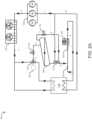
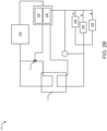
- the refrigeration circuit 100 may include one or more thermal batteries 110 fluidically coupled to the gas-cooler 104, the flash tank 106, the compressor unit 102, and the evaporators 108. The detailed operation and connection between the above-mentioned components of the refrigeration circuit 100 have been described later in conjunction with FIGs. 2A , 2B and 3A , 3B .
- a refrigerant such as CO 2 , and the like may be circulated through the refrigeration circuit 100.
- a low-pressure vapor line (using a conduit) may deliver the refrigerant to the compressor(s) 102 in gaseous form.
- the compressor(s) 102 may then increase the pressure of the refrigerant and deliver high-pressure refrigerant to the condenser or gas-cooler 104 through a high-pressure line.
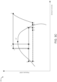
- the compressor unit 102 increases the pressure and enthalpy of the refrigerant from point 1 to point 2. Further, the pressure and enthalpy of the refrigerant reduce from point 2 to point 3 while passing through the gas-cooler 104.
- the gas-cooler 104 may be configured to transfer heat from the refrigerant to the environment, reducing the temperature of the refrigerant in the process. This reduction in temperature condenses the refrigerant from a vapor to a liquid phase.
- the refrigerant leaving the outlet of the gas-cooler 104 may be two-phase, liquid and vapor refrigerant. The majority of the refrigerant may be liquid, with a small amount of vapor remaining.
- the gas-cooler 104 may comprise two fans which may be configured to blow air through the condenser of the gas-cooler 104 to enhance heat transfer from the refrigerant to the environment, however, it will be appreciated that more or fewer than two fans can also be present.
- the two-phase refrigerant leaving the outlet of the gas-cooler 104 may enter the flash tank 106 through the flash tank inlet. Additionally, a high-pressure valve 116 (HPV) may be installed between the outlet of the gas-cooler 104 and the flash tank inlet. As shown in the PH diagram of FIG. 2C and 3C , the pressure of the refrigerant reduces from point 3-4 or 3'-4' but enthalpy remains the same. Within the flash tank 106, the two-phase refrigerant may be separated due to gravity into a liquid portion in the lower part of the flash tank 106 and a vapor portion in the upper part of the flash tank 106.
- the refrigerant in the vapor portion of the flash tank 106 may leave via the vapor outlet and return to the compressor unit 102.
- the enthalpy of the vapor refrigerant leaving the vapor outlet of the flash tank 106 reduce from point 4-5 but the pressure remains the same.
- the refrigerant in the liquid portion leaves the flash tank 106 via the liquid outlet and is delivered to an expansion valve 120, and then enters the evaporator 108.
- the enthalpy of the liquid refrigerant leaving the vapor outlet of the flash tank 106 increases from point 4-6 but pressure remains the same.
- the expansion valve 120 may not be necessary. In this case, a bypass line (not shown) may be employed.
- the evaporator 108 heat may be transferred from the environment to the liquid refrigerant. This heat may cause the refrigerant to vaporize, thereby removing heat from the environment. As shown in the PH diagram of FIG. 2C and 3C , the enthalpy of the refrigerant leaving the outlet of the evaporator 108 increases from point 7-9 but pressure remains the same.
- the evaporator 108 may be associated with a refrigeration load such as cabinets, wherein the heat may be transferred from the cabinet storage space to the liquid refrigerant, which may cause the refrigerant to vaporize and cool the cabinet storage space.
- the resulting refrigerant vapor may leave the evaporator 108 via the outlet of the evaporator 108 and be delivered to the thermal battery and then to the compressors 102 for further compression and circulation in the refrigeration circuit 100.
- the refrigeration circuit 100 may include a thermal battery 110 comprising a first inlet, a first outlet, a second inlet, and a second outlet, which may allow the flow of refrigerant therethrough to allow loading (freezing/cooling) or melting (heating) of a buffer within the thermal battery 110.
- the outlet of the compressor unit 102 may be fluidically coupled to the inlet of the gas-cooler 104 and the inlet of the compressor unit 102 may be fluidically coupled to the second outlet of the thermal battery 110.
- the refrigeration circuit 100 may include a three-way valve 112 comprising a first port, a second port, and a third port.
- the outlet of the gas-cooler 104 may be fluidically coupled to the first port of the three-way valve 112 as well as the first inlet of the thermal battery 110.
- the first outlet of the thermal battery 110 may be fluidically coupled to the second port of the three-way valve 112 and the third port of the three-way valve 112 may be fluidically coupled to the inlet of the flash tank 106.
- a high-pressure valve (HPV) 116 may be configured between the outlet of the gas-cooler 104 and the inlet of the flash tank 106.
- the vapor outlet of the flash tank 106 may be fluidically coupled to the inlet of the compressor unit 102 via a heat exchanger 114 such as but not limited to a brazed-plate heat exchanger.
- a medium pressure valve (MPV) 118 may be configured between the vapor outlet of the flash tank 106 and the heat exchanger 114. As shown in the PH diagram of FIG. 2C and 3C , the MPV 118 may lower the pressure of the vapor refrigerant from point 6-8.
- the second inlet of the thermal battery 110 may be fluidically coupled to the outlet of the one or more evaporators 108.
- the vapor outlet and the liquid outlet of the flash tank 106 may be fluidically coupled to the inlet of the one or more evaporators 108 via the heat exchanger 114 and a first expansion valve 120-1 (optional).
- the vapor outlet and the liquid outlet of the flash tank 106 may be fluidically coupled to the second inlet of the thermal battery 110 via the heat exchanger 114 and a second expansion valve 120-1 (optional).
- the first expansion valve 120-1 may lower the pressure of the refrigerant (coming from the flash tank 106) from point 5-7, but the enthalpy of the liquid refrigerant (point 5-7) remains less than that of the vapor refrigerant (point 6-8) coming from the flash tank 106.
- the refrigeration circuit 100 may include a thermal battery 110 comprising an inlet, and an outlet, which may allow the flow of refrigerant therethrough to allow loading (freezing/cooling) or melting (heating) of a buffer within the thermal battery 110.
- the outlet of the compressor unit 102 may be fluidically coupled to the inlet of the gas-cooler 104 and the inlet of the compressor unit 102 may be fluidically coupled to the second outlet of the thermal battery 110.
- the refrigeration circuit 100 may include a three-way valve 112 comprising a first port, a second port, and a third port.
- the outlet of the gas-cooler 104 may be fluidically coupled to the inlet of the thermal battery 110 via a first heat exchanger 114-1, and a second heat exchanger 114-2, which may be a brazed-plate heat exchanger.
- the outlet of the thermal battery 110 may be fluidically coupled to the second port of the three-way valve 112 and the outlet of the thermal battery 110 may be further fluidically coupled to the inlet of the compressor unit 102 via the three-way valve 112 and the second heat exchanger 114-2.
- the first port of the three-way valve 112 may be fluidically coupled to the inlet of the thermal battery 110 via the second heat exchanger 114-2 and the third port of the three-way valve 112 may be fluidically coupled to the inlet of the flash tank 106 via the first heat exchanger 114-1.
- a high-pressure valve (HPV) 116 may be configured between the first heat exchanger 114-1 and the inlet of the flash tank 106.
- the vapor outlet of the flash tank 106 may be fluidically coupled to the inlet of the compressor unit 102 via a third heat exchanger 114-3.
- a medium pressure valve (MPV) 118 may be configured between the vapor outlet of the flash tank 106 and the third heat exchanger. As shown in the PH diagram of FIG. 2C and 3C , the MPV 118 may lower the pressure of the vapor refrigerant from point 6-8.
- the inlet of the thermal battery 110 may be fluidically coupled to the outlet of the one or more evaporators 108 via the second heat exchanger 114-2.
- the liquid outlet and the vapor outlet of the flash tank 106 may be fluidically coupled to the inlet of the one or more evaporators 108 via the third heat exchanger 114-3, and a first expansion valve 120-1 (optional). Further, the liquid outlet and the vapor outlet of the flash tank 106 may be fluidically coupled to the inlet of the thermal battery 110 via the second heat exchanger 114-2, the third heat exchanger 114-3, and a second expansion valve 120-1. As shown in the PH diagram of FIG.
- the first expansion valve 120-1 may lower the pressure of the refrigerant (coming from the flash tank 106) from point 5-7, but the enthalpy of the liquid refrigerant (point 5-7) remains less than that of the vapor refrigerant (point 6-8) coming from the flash tank 106.
- the refrigerant leaving the outlet of the gas-cooler 104 and/or the refrigerant leaving the outlet of the evaporator 108 or the flash tank 106 may be allowed to flow through the thermal battery 110 where the buffer of the thermal battery 110 may be loaded or melted based on the temperature of the refrigerant flowing through the thermal battery 110.
- the flow of the refrigerant between the gas-cooler 104 and the thermal battery 110, the thermal battery 110 and the evaporator 108, and/or the thermal battery 110 and the compressor unit 102 may be controlled based on the ambient temperature at the gas-cooler 104 and/or the electricity grid information associated with an electrical grid connected to the refrigerant circuit.
- the flash tank 106 may be operated by the electrical power received from the electrical grid to supply and evaporate the refrigerant in the thermal battery 110 to cool the buffer to a first temperature so that the flash tank 106 may act as a heat sink.
- the buffer of the thermal battery 110 acting as the heat sink may be melted to cool the refrigerant by allowing the refrigerant to flow through the thermal battery 110.
- the cooled refrigerant may then exit the first outlet of the thermal battery 110 and be supplied to the outlet of the gas-cooler 104 via the three-way valve 112 to reduce the temperature at the outlet of the gas-cooler 104 below the ambient temperature. This may help reduce the flash vapor generated from the gas-cooler 104 as shown in FIG. 2C and 3C .
- the flash vapor may be removed or the entropy inlet of the expansion valve or HPV 116 may be reduced. Further, less flash vapor means from 6-8, there is less mass flow of vapor, which may be throttled to the level of the evaporation temperature of the empty compressor and therefore less compressor work may be needed to recompress this flash vapor gas amount.
- a simple expansion valve may be used to load the buffer, however, to optimize the refrigeration circuit 100 and installations, the cabinets or cold room evaporators 108 may be operated in dry expansion mode, which usually utilizes superheated gas at 6-8 Kelvin temperature. Still, a section of the evaporator 108 may be a super-heated section with low strength, so, the installations may be operated in a semi-flooded mode, where the installations are operated with a very low superheat control signal, which ends up in having 10% of liquid at the end of the evaporator, which is usually desirable because liquid refrigerant will damage the bearings in the compressor.
- the refrigeration circuit 100 may allow the thermal battery 110 to operate as a heat source to evaporate the overheated liquid, such that at the outlet of the thermal battery 110 may provide superheated gas, which is good for the compressors 102.
- the buffer acting as the heat sink may be melted to cool the refrigerant flowing therethrough to a second temperature.
- the cool refrigerant may then be supplied to the one or more evaporators 108 associated with the refrigeration installations.
- heat may be transferred from the cabinet storage space to the cool refrigerant coming from the thermal battery 110, which may cause the refrigerant to heat and vaporize, and cool the storage space of the cabinets.
- the refrigeration circuit 100 can ramp up and ramp down simultaneously on multiple refrigeration installations, when the electrical load is either in the positive or the negative direction.
- heat may be transferred from the cabinet storage space to the liquid refrigerant, which may cause the refrigerant to heat and vaporize.
- the heated refrigerant leaving the outlet of the evaporator 108 may be delivered to the compressors 102 through the thermal battery 110 where the buffer may store the heat and act as a heat source.
- the liquid/vapor refrigerant leaving the outlet of the flash tank 106 may be delivered through the thermal battery 110, where the temperature of the refrigerant may be further increased to vaporize the refrigerant using the heat stored in the thermal battery 110 (acting as heat source).
- the supply of heat by the thermal battery 110 may facilitate the heating of the refrigerant to a super-heated temperature, which may be supplied to the compressor unit 102, thereby reducing the load on the compressors 102 and improving the longevity of the compressors 102.
- the buffer of the thermal battery 110 may be a phase-changing material (PCM) such as but not limited to paraffin, however, water may also be used as the PCM since evaporation is maintained around minus eight to minus five degrees Celsius in the invention. Fresh water may be used without the need for brine or paraffin as PCM.
- PCM phase-changing material
- the refrigeration circuit 100 may include a controller 122 operatively coupled to the components of the refrigeration circuit 100.
- the controller 122 may be configured to monitor one or more parameters associated with the refrigeration circuit 100 using flow meters installed in conduits (lines) used for fluidically connecting the components of the refrigeration circuit 100. Further, the controller 122 may involve pressure sensors and temperature sensors to monitor the temperature and pressure of the refrigerant within the refrigeration circuit 100.
- the controller 122 can include a communication unit that connects the controller 122 to the components of the refrigeration circuit 100 and an electrical grid. The controller 122 may be in communication with a database of one or more electric power service providers associated with the electrical grid.
- the controller 122 is configured to receive, from the database, data pertaining to electricity pricing associated with the electrical grid connected to the refrigerant circuit.
- the controller 122 may accordingly control the operation of the components of the refrigeration circuit 100 to control the flow of a refrigerant associated with the refrigeration circuit 100 between one or more of the gas-cooler 104 and the thermal battery 110, the thermal battery 110 and the evaporator 108, and/or the thermal battery 110 and the compressor unit 102.
- the controller 122 enables the flash tank 106 to supply and evaporate the refrigerant in the thermal battery 110 to cool a buffer associated with the thermal battery 110.
- the controller 122 may enable the melting of the buffer of the thermal battery 110 to cool the refrigerant flowing therethrough and supply the cooled refrigerant to the outlet of the gas-cooler 104 to reduce the temperature at the outlet of the gas-cooler 104 below the ambient temperature, thereby reducing flash vapor and reducing the load on the compressors 102.
- the controller 122 may enable the melting of the buffer acting to cool the refrigerant flowing therethrough and further enable the supply of the cooled refrigerant to the one or more evaporators 108. Furthermore, the controller 122 may be configured to enable the flow of the refrigerant being heated in the refrigeration circuit 100, through the thermal battery 110 to store the thermal energy received from the heated refrigerant in the buffer such that the thermal battery 110 acts as a heat source. Thus, the controller 122 may enable the thermal battery 110 to act as the heat source to heat the refrigerant flowing therethrough to a super-heated temperature; and supply the super-heated refrigerant from the thermal battery 110 to the compressor unit 102.
- the refrigeration circuit provides an improved, reliable, and power-efficient refrigeration circuit having a thermal storage.
- the refrigeration circuit allows loading (cooling/freezing) of the buffer when electricity pricing is cheaper and may further allow the buffer to melt against the gas-cooler outlet to reduce the power consumption if the cost of electricity is high or if ambient conditions are on a peak period of the day. Peak periods are defined as times at which the electricity usage is greater than average.
- the refrigeration circuit may allow a lift of evaporation temperature in the refrigeration circuit, which may improve the overall efficiency.
- the refrigeration circuit also allows the users to easily retrofit refrigeration cabinets (loads) and size the initial equipment smaller.
Landscapes
- Engineering & Computer Science (AREA)
- Physics & Mathematics (AREA)
- Mechanical Engineering (AREA)
- Thermal Sciences (AREA)
- General Engineering & Computer Science (AREA)
- Fluid Mechanics (AREA)
- Chemical & Material Sciences (AREA)
- Chemical Kinetics & Catalysis (AREA)
- Devices That Are Associated With Refrigeration Equipment (AREA)
Applications Claiming Priority (1)
| Application Number | Priority Date | Filing Date | Title |
|---|---|---|---|
| US202263387665P | 2022-12-15 | 2022-12-15 |
Publications (1)
| Publication Number | Publication Date |
|---|---|
| EP4386280A1 true EP4386280A1 (fr) | 2024-06-19 |
Family
ID=89223940
Family Applications (1)
| Application Number | Title | Priority Date | Filing Date |
|---|---|---|---|
| EP23217289.0A Pending EP4386280A1 (fr) | 2022-12-15 | 2023-12-15 | Circuit de réfrigération avec stockage thermique |
Country Status (3)
| Country | Link |
|---|---|
| US (1) | US20240200841A1 (fr) |
| EP (1) | EP4386280A1 (fr) |
| CN (1) | CN118208860A (fr) |
Citations (4)
| Publication number | Priority date | Publication date | Assignee | Title |
|---|---|---|---|---|
| US9903621B1 (en) * | 2017-03-28 | 2018-02-27 | Inficold Inc. | Cooling system with thermal battery |
| US20200348056A1 (en) * | 2017-11-10 | 2020-11-05 | Hussmann Corporation | Subcritical co2 refrigeration system using thermal storage |
| US11149971B2 (en) * | 2018-02-23 | 2021-10-19 | Emerson Climate Technologies, Inc. | Climate-control system with thermal storage device |
| EP3961123A1 (fr) * | 2020-08-31 | 2022-03-02 | Mitsubishi Electric R&D Centre Europe B.V. | Système de pompe à chaleur à compression de vapeur et procédé de fonctionnement d'un système de pompe à chaleur à compression de vapeur |
Family Cites Families (2)
| Publication number | Priority date | Publication date | Assignee | Title |
|---|---|---|---|---|
| JP5327308B2 (ja) * | 2011-09-30 | 2013-10-30 | ダイキン工業株式会社 | 給湯空調システム |
| US20170211862A1 (en) * | 2016-01-25 | 2017-07-27 | Sharp Kabushiki Kaisha | Dual temperature heat pump system |
-
2023
- 2023-12-13 US US18/538,472 patent/US20240200841A1/en active Pending
- 2023-12-13 CN CN202311708587.7A patent/CN118208860A/zh active Pending
- 2023-12-15 EP EP23217289.0A patent/EP4386280A1/fr active Pending
Patent Citations (4)
| Publication number | Priority date | Publication date | Assignee | Title |
|---|---|---|---|---|
| US9903621B1 (en) * | 2017-03-28 | 2018-02-27 | Inficold Inc. | Cooling system with thermal battery |
| US20200348056A1 (en) * | 2017-11-10 | 2020-11-05 | Hussmann Corporation | Subcritical co2 refrigeration system using thermal storage |
| US11149971B2 (en) * | 2018-02-23 | 2021-10-19 | Emerson Climate Technologies, Inc. | Climate-control system with thermal storage device |
| EP3961123A1 (fr) * | 2020-08-31 | 2022-03-02 | Mitsubishi Electric R&D Centre Europe B.V. | Système de pompe à chaleur à compression de vapeur et procédé de fonctionnement d'un système de pompe à chaleur à compression de vapeur |
Also Published As
| Publication number | Publication date |
|---|---|
| CN118208860A (zh) | 2024-06-18 |
| US20240200841A1 (en) | 2024-06-20 |
Similar Documents
| Publication | Publication Date | Title |
|---|---|---|
| US11089719B2 (en) | Computer room heat-pipe air conditioning system with emergency cooling function and control and method thereof | |
| US8245948B2 (en) | Co-generation and control method of the same | |
| US7210303B2 (en) | Transcritical heat pump water heating system using auxiliary electric heater | |
| JP4782462B2 (ja) | 地中熱利用ヒートポンプ装置、これを備えた地中熱利用装置、および地中熱利用ヒートポンプ装置の制御方法 | |
| US7104079B2 (en) | Heat pump | |
| US20150292775A1 (en) | Refrigeration system with phase change material | |
| CN118031483A (zh) | 蒸汽压缩制冷系统中的反循环除霜基于相变材料的增强 | |
| US20120048514A1 (en) | Cooling systems and methods | |
| US20100038441A1 (en) | Energy system with a heat pump | |
| US7024877B2 (en) | Water heating system | |
| CN106152840B (zh) | 热管系统、制冷系统及其控制方法 | |
| JP4377634B2 (ja) | 冷却システムの運転方法 | |
| JP2003279079A (ja) | 氷蓄熱システムおよび氷蓄熱システムによる暖房方法 | |
| CN117006724A (zh) | 温控机组、温度控制方法及温度控制装置 | |
| EP2678612B1 (fr) | Système de climatisation avec stockage de glace | |
| EP4386280A1 (fr) | Circuit de réfrigération avec stockage thermique | |
| EP3546854B1 (fr) | Dégivrage d'un système de pompe à chaleur par chaleur perdue | |
| EP3910265B1 (fr) | Système de refroidissement | |
| BRPI0915033B1 (pt) | sistema reversível para recuperação de energia calorífica por retirada e transferência de calorias de um ou vários meios em um outro ou vários outros meios quaisquer | |
| US20240361045A1 (en) | Thermal Energy Storage and Cooling Device With Isolating Heat Exchanger | |
| CN119697973A (zh) | 一种用于变频器房的气气热管降温器 | |
| CN203454320U (zh) | 制冷/制热系统 | |
| US20250003649A1 (en) | Heat pump | |
| CN111442550B (zh) | 制冷系统 | |
| JP2005188813A (ja) | サーモサイフォン式冷却装置 |
Legal Events
| Date | Code | Title | Description |
|---|---|---|---|
| PUAI | Public reference made under article 153(3) epc to a published international application that has entered the european phase |
Free format text: ORIGINAL CODE: 0009012 |
|
| STAA | Information on the status of an ep patent application or granted ep patent |
Free format text: STATUS: THE APPLICATION HAS BEEN PUBLISHED |
|
| AK | Designated contracting states |
Kind code of ref document: A1 Designated state(s): AL AT BE BG CH CY CZ DE DK EE ES FI FR GB GR HR HU IE IS IT LI LT LU LV MC ME MK MT NL NO PL PT RO RS SE SI SK SM TR |
|
| RIN1 | Information on inventor provided before grant (corrected) |
Inventor name: SHEN, REBECCA Inventor name: ANNAPRAGADA, SUBRAMANYARAVI Inventor name: HELLMANN, SASCHA |
|
| STAA | Information on the status of an ep patent application or granted ep patent |
Free format text: STATUS: REQUEST FOR EXAMINATION WAS MADE |
|
| 17P | Request for examination filed |
Effective date: 20241218 |
|
| STAA | Information on the status of an ep patent application or granted ep patent |
Free format text: STATUS: EXAMINATION IS IN PROGRESS |
|
| 17Q | First examination report despatched |
Effective date: 20260223 |