EP4386527A1 - Optischer virtueller druckknopf-berührungsbildschirm - Google Patents
Optischer virtueller druckknopf-berührungsbildschirm Download PDFInfo
- Publication number
- EP4386527A1 EP4386527A1 EP22214054.3A EP22214054A EP4386527A1 EP 4386527 A1 EP4386527 A1 EP 4386527A1 EP 22214054 A EP22214054 A EP 22214054A EP 4386527 A1 EP4386527 A1 EP 4386527A1
- Authority
- EP
- European Patent Office
- Prior art keywords
- light
- light guide
- push button
- touch panel
- emitting member
- Prior art date
- Legal status (The legal status is an assumption and is not a legal conclusion. Google has not performed a legal analysis and makes no representation as to the accuracy of the status listed.)
- Withdrawn
Links
Images


Classifications
-
- G—PHYSICS
- G06—COMPUTING OR CALCULATING; COUNTING
- G06F—ELECTRIC DIGITAL DATA PROCESSING
- G06F3/00—Input arrangements for transferring data to be processed into a form capable of being handled by the computer; Output arrangements for transferring data from processing unit to output unit, e.g. interface arrangements
- G06F3/01—Input arrangements or combined input and output arrangements for interaction between user and computer
- G06F3/03—Arrangements for converting the position or the displacement of a member into a coded form
- G06F3/033—Pointing devices displaced or positioned by the user, e.g. mice, trackballs, pens or joysticks; Accessories therefor
- G06F3/0354—Pointing devices displaced or positioned by the user, e.g. mice, trackballs, pens or joysticks; Accessories therefor with detection of two-dimensional [2D] relative movements between the device, or an operating part thereof, and a plane or surface, e.g. 2D mice, trackballs, pens or pucks
- G06F3/03547—Touch pads, in which fingers can move on a surface
-
- G—PHYSICS
- G06—COMPUTING OR CALCULATING; COUNTING
- G06F—ELECTRIC DIGITAL DATA PROCESSING
- G06F3/00—Input arrangements for transferring data to be processed into a form capable of being handled by the computer; Output arrangements for transferring data from processing unit to output unit, e.g. interface arrangements
- G06F3/01—Input arrangements or combined input and output arrangements for interaction between user and computer
- G06F3/048—Interaction techniques based on graphical user interfaces [GUI]
- G06F3/0484—Interaction techniques based on graphical user interfaces [GUI] for the control of specific functions or operations, e.g. selecting or manipulating an object, an image or a displayed text element, setting a parameter value or selecting a range
- G06F3/04842—Selection of displayed objects or displayed text elements
-
- G—PHYSICS
- G06—COMPUTING OR CALCULATING; COUNTING
- G06F—ELECTRIC DIGITAL DATA PROCESSING
- G06F3/00—Input arrangements for transferring data to be processed into a form capable of being handled by the computer; Output arrangements for transferring data from processing unit to output unit, e.g. interface arrangements
- G06F3/01—Input arrangements or combined input and output arrangements for interaction between user and computer
- G06F3/048—Interaction techniques based on graphical user interfaces [GUI]
- G06F3/0487—Interaction techniques based on graphical user interfaces [GUI] using specific features provided by the input device, e.g. functions controlled by the rotation of a mouse with dual sensing arrangements, or of the nature of the input device, e.g. tap gestures based on pressure sensed by a digitiser
- G06F3/0488—Interaction techniques based on graphical user interfaces [GUI] using specific features provided by the input device, e.g. functions controlled by the rotation of a mouse with dual sensing arrangements, or of the nature of the input device, e.g. tap gestures based on pressure sensed by a digitiser using a touch-screen or digitiser, e.g. input of commands through traced gestures
-
- H—ELECTRICITY
- H03—ELECTRONIC CIRCUITRY
- H03K—PULSE TECHNIQUE
- H03K17/00—Electronic switching or gating, i.e. not by contact-making and –breaking
- H03K17/94—Electronic switching or gating, i.e. not by contact-making and –breaking characterised by the way in which the control signals are generated
- H03K17/96—Touch switches
- H03K17/962—Capacitive touch switches
- H03K17/9622—Capacitive touch switches using a plurality of detectors, e.g. keyboard
-
- H—ELECTRICITY
- H03—ELECTRONIC CIRCUITRY
- H03K—PULSE TECHNIQUE
- H03K2217/00—Indexing scheme related to electronic switching or gating, i.e. not by contact-making or -breaking covered by H03K17/00
- H03K2217/94—Indexing scheme related to electronic switching or gating, i.e. not by contact-making or -breaking covered by H03K17/00 characterised by the way in which the control signal is generated
- H03K2217/96—Touch switches
- H03K2217/9607—Capacitive touch switches
- H03K2217/960755—Constructional details of capacitive touch and proximity switches
-
- H—ELECTRICITY
- H03—ELECTRONIC CIRCUITRY
- H03K—PULSE TECHNIQUE
- H03K2217/00—Indexing scheme related to electronic switching or gating, i.e. not by contact-making or -breaking covered by H03K17/00
- H03K2217/94—Indexing scheme related to electronic switching or gating, i.e. not by contact-making or -breaking covered by H03K17/00 characterised by the way in which the control signal is generated
- H03K2217/96—Touch switches
- H03K2217/9607—Capacitive touch switches
- H03K2217/960785—Capacitive touch switches with illumination
- H03K2217/96079—Capacitive touch switches with illumination using a single or more light guides
Definitions
- the present invention relates to an optically control device and, more particularly, to an optical virtual push button touch panel.
- a conventional game console or device is controlled through physical push buttons mounted on a keyboard.
- the keyboard has a complicated mechanic structure that allows the push buttons to be pressed, to rebound or bounce back, and to produce a control signal to the circuit board.
- the mechanic structure is easily worn out during a long-term utilization and will be broken due to an excessive pressing force.
- a light source with different colors is mounted in the push buttons so that the push buttons present a lighting display with different colors.
- the colors of the push buttons from the light source are fixed and cannot be changed or adjusted, thereby limiting the aesthetic quality of the push buttons.
- the primary objective of the present invention is to provide an optical virtual push button touch panel that is operated in a virtual manner without needing a traditional push button.
- an optical virtual push button touch panel comprising a substrate, a light emitting member, a light guide plate, a light permeable plate, and a touch control sensing member.
- the substrate is provided with a mounting slot and a fixed structure.
- the fixed structure surrounds the mounting slot.
- the light emitting member is mounted in the fixed structure.
- the light emitting member generates a light source directed toward the mounting slot.
- the light guide plate defines multiple light guide structures.
- the light source of the light emitting member is guided and converged by the light guide structures to produce a light source convergence.
- the light permeable plate is mounted on a side of the substrate and covers the light guide plate.
- the touch control sensing member is located between the light permeable plate and the light guide plate.
- the touch control sensing member defines multiple contact zones aligning with the light guide structures respectively.
- One of the contact zones produces a coupling capacitance through the light permeable plate and drives the light emitting member to generate the light source, and one of the light guide structures converges the light source toward one of the contact zones.
- the optical virtual push button touch panel is operated easily without having to press a push button, thereby facilitating the user operating the optical virtual push button touch panel.
- the optical virtual push button touch panel has a simplified construction to decrease the cost of fabrication.
- the optical virtual push button touch panel produces a diverse lighting effect through the touch control sensing member and the light emitting member, thereby enhancing the aesthetic quality.
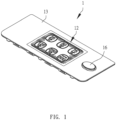
- an optical virtual push button touch panel 1 in accordance with the preferred embodiment of the present invention comprises a substrate (or base plate) 10, a light emitting member 11, a light guide plate (or light conductive board) 12, a light permeable plate (or transparent board) 13, and a touch control sensing member 14.
- the substrate 10 is provided with a mounting slot 100 and a fixed structure (or fixture) 102.
- the fixed structure 102 surrounds the mounting slot 100.
- the light emitting member 11 is mounted in the mounting slot 100 and secured by the fixed structure 102.
- the light emitting member 11 surrounds the fixed structure 102 and generates a light source directed toward the mounting slot 100.
- the light guide plate 12 is mounted in the mounting slot 100 and defines multiple light guide (or indicating) structures 120.
- the light source of the light emitting member 11 is guided and converged (or gathered or concentrated) by the light guide structures 120 to produce a light source convergence.
- the light permeable plate 13 is mounted on a side of the substrate 10 and covers the light guide plate 12.
- the touch control sensing member 14 is mounted in the mounting slot 100 and located between the light permeable plate 13 and the light guide plate 12.
- the touch control sensing member 14 defines multiple contact zones 140 aligning with the light guide structures 120 respectively.
- One of the contact zones 140 produces a coupling capacitance (or capacitor or condenser) through the light permeable plate 13 and drives the light emitting member 11 to generate the light source, and one of the light guide structures 120 converges the light source toward one of the contact zones 140.
- the substrate 10 is provided with an operation module 15 and a connector (or receiver) 104.
- the connector 104 is electrically connected with the operation module 15.
- the operation module 15 is electrically connected with the light emitting member 11.
- the operation module 15 controls generation of the light source of the light emitting member 11.
- the touch control sensing member 14 is provided with a signal connecting (or transmitting) portion 142 electrically connected with the connector 104 of the substrate 10 so that the touch control sensing member 14 is electrically connected with the operation module 15.
- each of the light guide structures 120 has an arrangement (or appearance) including a number, a character, a figure or a matrix.
- the arrangement of each of the light guide structures 120 is formed by special inks such as infrared inks, recessive fluorescent inks, light-transmitting inks, machining or tungsten wires.
- each of the light guide structures 120 is formed by a groove which has two opposite faces and a hollow bottom face.
- the optical virtual push button touch panel 1 further comprises a push button device 16 mounted on the substrate 10.
- the push button device 16 is connected with a switch for starting an external device.
- the light guide plate 12 is made of transparent material, including an optical acrylic board, PC, PVC, glass, transparent resin or transparent wood.
- the light guide plate 12 When the light guide plate 12 is made of transparent wood, the internal texture of the wood is not changed after the color of the wood fades. Then, the wood is soaked so that the epoxy resin is absorbed by the tiny conduits that are used to transport nutrients in the wood. In such a manner, the epoxy resin has a refractive index close to that of optical glass so that the light passes through the wood, and the wood is made transparent, and
- the light permeable plate 13 is made of transparent material, including glass or plastics.
- the light emitting member 11 is an LED strip, a lighting board or an optical fiber strip.
- the fixed structure 102 of the substrate 10 is formed on a peripheral wall of the mounting slot 100 and is bent inward for fixing the light emitting member 11.
- the light emitting member 11 surrounds and is fixed in the fixed structure 102.
- the light emitting member 11 has a terminal provided with an electric plug electrically connected with the operation module 15 of the substrate 10.
- the operation module 15 provides an electric power to the light emitting member 11 for lighting.
- the operation module 15 is loaded with multiple lighting modes.
- the operation module 15 is a circuit board that is electrically connected with an external power supply and includes an operation unit for loading the lighting modes.
- the contact zones 140 of the touch control sensing member 14 are formed by a design of potential distribution.
- Each of the contact zones 140 corresponds to one of the lighting modes of the operation module 15.
- Each of the lighting modes includes color variation, flashing variation or monochrome display.
- the coupling capacitance is generated when the light permeable plate 13 is touched by a human body so that one of the contact zones 140 is triggered, and the signal connecting portion 142 of the touch control sensing member 14 transmits a signal to the connector 104 of the substrate 10 so that the operation module 15 drives one of the lighting modes respectively.
- the light guide plate 12 defines six light guide structures 120, and the touch control sensing member 14 defines six contact zones 140 aligning with the light guide structures 120 respectively.
- the light guide structures 120 are arranged to form a matrix, and each of the light guide structures 120 presents a number.
- the light guide structures 120 light in a non-contact manner.
- the light permeable plate 13 is a capacitance (or capacitor) touch board which includes a glass layer, an ITO (indium tin oxide) layer coated on an inner face of the glass layer, and a glass protecting layer (made of silica) mounted on an outer face of the glass layer.
- the ITO layer is served as a working surface with four corners releasing or discharging four electrodes.
- All of the electrodes have the same potential when the human body is not in contact with the light permeable plate 13, so that no electric current passes through the light permeable plate 13.
- a coupling capacitor or capacitance is generated on the surface of the light permeable plate 13.
- the coupling capacitor is a direct conductor, and the user's finger absorbs a small electric current from the contact point with the light permeable plate 13, so that the electric current flows outward from the four electrodes of the four corners of the light permeable plate 13 respectively.
- the electric current value passing each of the four electrodes is proportional to the distance between the user's finger and each of the four corners of the light permeable plate 13.
- the contact position of the user's finger with the light permeable plate 13 is calculated to decide the location of the light permeable plate 13 corresponding to or aligning with one of the contact zones 140.
- Both of the light permeable plate 13 and the light guide plate 12 are made of transparent material, so that the light guide structures 120 of the light guide plate 12 are seen directly through the light permeable plate 13.
- the numbers 25, 50, 75, 125, 250, and 500 of the light guide structures 120 correspond to the contact zones 140 of the touch control sensing member 14 respectively.
- a signal indicating the position of the respective contact zone 140 is transmitted through the signal connecting portion 142 of the touch control sensing member 14 to the connector 104 of the substrate 10, and the operation module 15 drives one of the lighting modes respectively, so that the light emitting member 11 is driven by the operation module 15, and the light source of the light emitting member 11 is directed toward the respective light guide structure 120.
- the light is converged on the respective contact zone 140 to indicate the number "25”.
- the light permeable plate 13 is touched by the human body to generate a light source on the touch control sensing member 14 through an action of the light guide plate 12.
- the optical virtual push button touch panel 1 is operated easily without having to press a push button, thereby facilitating the user operating the optical virtual push button touch panel 1.
- the optical virtual push button touch panel 1 has a simplified construction to decrease the cost of fabrication.
- the optical virtual push button touch panel 1 produces a diverse lighting effect through the touch control sensing member 14 and the light emitting member 11, thereby enhancing the aesthetic quality.
Landscapes
- Engineering & Computer Science (AREA)
- General Engineering & Computer Science (AREA)
- Theoretical Computer Science (AREA)
- Human Computer Interaction (AREA)
- Physics & Mathematics (AREA)
- General Physics & Mathematics (AREA)
- Push-Button Switches (AREA)
Priority Applications (1)
| Application Number | Priority Date | Filing Date | Title |
|---|---|---|---|
| EP22214054.3A EP4386527A1 (de) | 2022-12-16 | 2022-12-16 | Optischer virtueller druckknopf-berührungsbildschirm |
Applications Claiming Priority (1)
| Application Number | Priority Date | Filing Date | Title |
|---|---|---|---|
| EP22214054.3A EP4386527A1 (de) | 2022-12-16 | 2022-12-16 | Optischer virtueller druckknopf-berührungsbildschirm |
Publications (1)
| Publication Number | Publication Date |
|---|---|
| EP4386527A1 true EP4386527A1 (de) | 2024-06-19 |
Family
ID=84537599
Family Applications (1)
| Application Number | Title | Priority Date | Filing Date |
|---|---|---|---|
| EP22214054.3A Withdrawn EP4386527A1 (de) | 2022-12-16 | 2022-12-16 | Optischer virtueller druckknopf-berührungsbildschirm |
Country Status (1)
| Country | Link |
|---|---|
| EP (1) | EP4386527A1 (de) |
Citations (2)
| Publication number | Priority date | Publication date | Assignee | Title |
|---|---|---|---|---|
| US20180217669A1 (en) * | 2017-03-29 | 2018-08-02 | Apple Inc. | Device having integrated interface system |
| US20220206343A1 (en) * | 2020-12-29 | 2022-06-30 | Tpk Touch Solutions (Xiamen) Inc. | Touch front light module and touch display device |
-
2022
- 2022-12-16 EP EP22214054.3A patent/EP4386527A1/de not_active Withdrawn
Patent Citations (2)
| Publication number | Priority date | Publication date | Assignee | Title |
|---|---|---|---|---|
| US20180217669A1 (en) * | 2017-03-29 | 2018-08-02 | Apple Inc. | Device having integrated interface system |
| US20220206343A1 (en) * | 2020-12-29 | 2022-06-30 | Tpk Touch Solutions (Xiamen) Inc. | Touch front light module and touch display device |
Similar Documents
| Publication | Publication Date | Title |
|---|---|---|
| CN202050396U (zh) | 触控装置 | |
| US7962040B2 (en) | Remote control transmitter | |
| US9088283B2 (en) | Touch device | |
| US10581430B2 (en) | Backlighting appliance deadfronted user interfaces | |
| TWI470312B (zh) | 手持電子裝置 | |
| CN104350568B (zh) | 触摸滑动单元和具有触摸滑动单元的微波炉 | |
| CN101682945B (zh) | 加热烹调器 | |
| US11754771B1 (en) | Optical virtual push button touch panel | |
| JP2016036498A (ja) | 操作パネル及び洗濯機 | |
| EP4386527A1 (de) | Optischer virtueller druckknopf-berührungsbildschirm | |
| US10082296B2 (en) | Operating device for domestic appliance | |
| KR101600803B1 (ko) | 터치형 키입력바 | |
| CN211124882U (zh) | 显示装置及家电设备 | |
| JP2006128020A (ja) | 静電容量式スイッチ装置 | |
| CN218237596U (zh) | 一种基于红外感应的面板控制装置及吸油烟机 | |
| CN217485033U (zh) | 显示设备、人机交互系统及家用电器 | |
| WO2024036782A1 (zh) | 一种基于光通道的输入设备 | |
| TWM642308U (zh) | 光學虛擬按鍵觸控面板 | |
| CN218938935U (zh) | 光学虚拟按键触控面板 | |
| TWM580716U (zh) | 發光扶手墊 | |
| CN215628805U (zh) | 可操作显示屏及衣物处理设备 | |
| JP2023109735A (ja) | 表示装置、表示方法、ヒューマンマシンインタラクションシステム、および家電製品 | |
| CN208706501U (zh) | 高灵敏度光轴发光机械键盘 | |
| CN211016377U (zh) | 显示装置及家电设备 | |
| CN222510662U (zh) | 一种可切换按键标识的游戏手柄 |
Legal Events
| Date | Code | Title | Description |
|---|---|---|---|
| PUAI | Public reference made under article 153(3) epc to a published international application that has entered the european phase |
Free format text: ORIGINAL CODE: 0009012 |
|
| STAA | Information on the status of an ep patent application or granted ep patent |
Free format text: STATUS: THE APPLICATION HAS BEEN PUBLISHED |
|
| AK | Designated contracting states |
Kind code of ref document: A1 Designated state(s): AL AT BE BG CH CY CZ DE DK EE ES FI FR GB GR HR HU IE IS IT LI LT LU LV MC ME MK MT NL NO PL PT RO RS SE SI SK SM TR |
|
| STAA | Information on the status of an ep patent application or granted ep patent |
Free format text: STATUS: THE APPLICATION IS DEEMED TO BE WITHDRAWN |
|
| 18D | Application deemed to be withdrawn |
Effective date: 20241220 |