EP4386665B1 - Bildverarbeitungsvorrichtung, -verfahren und -programm - Google Patents
Bildverarbeitungsvorrichtung, -verfahren und -programm Download PDFInfo
- Publication number
- EP4386665B1 EP4386665B1 EP23214590.4A EP23214590A EP4386665B1 EP 4386665 B1 EP4386665 B1 EP 4386665B1 EP 23214590 A EP23214590 A EP 23214590A EP 4386665 B1 EP4386665 B1 EP 4386665B1
- Authority
- EP
- European Patent Office
- Prior art keywords
- pixel
- running
- pixels
- tubular structures
- image processing
- Prior art date
- Legal status (The legal status is an assumption and is not a legal conclusion. Google has not performed a legal analysis and makes no representation as to the accuracy of the status listed.)
- Active
Links
Images






Classifications
-
- G—PHYSICS
- G06—COMPUTING OR CALCULATING; COUNTING
- G06V—IMAGE OR VIDEO RECOGNITION OR UNDERSTANDING
- G06V10/00—Arrangements for image or video recognition or understanding
- G06V10/70—Arrangements for image or video recognition or understanding using pattern recognition or machine learning
- G06V10/762—Arrangements for image or video recognition or understanding using pattern recognition or machine learning using clustering, e.g. of similar faces in social networks
- G06V10/7635—Arrangements for image or video recognition or understanding using pattern recognition or machine learning using clustering, e.g. of similar faces in social networks based on graphs, e.g. graph cuts or spectral clustering
-
- G—PHYSICS
- G06—COMPUTING OR CALCULATING; COUNTING
- G06T—IMAGE DATA PROCESSING OR GENERATION, IN GENERAL
- G06T7/00—Image analysis
- G06T7/10—Segmentation; Edge detection
- G06T7/162—Segmentation; Edge detection involving graph-based methods
-
- G—PHYSICS
- G06—COMPUTING OR CALCULATING; COUNTING
- G06T—IMAGE DATA PROCESSING OR GENERATION, IN GENERAL
- G06T7/00—Image analysis
- G06T7/0002—Inspection of images, e.g. flaw detection
- G06T7/0012—Biomedical image inspection
-
- G—PHYSICS
- G06—COMPUTING OR CALCULATING; COUNTING
- G06T—IMAGE DATA PROCESSING OR GENERATION, IN GENERAL
- G06T7/00—Image analysis
- G06T7/10—Segmentation; Edge detection
- G06T7/11—Region-based segmentation
-
- G—PHYSICS
- G06—COMPUTING OR CALCULATING; COUNTING
- G06T—IMAGE DATA PROCESSING OR GENERATION, IN GENERAL
- G06T7/00—Image analysis
- G06T7/10—Segmentation; Edge detection
- G06T7/181—Segmentation; Edge detection involving edge growing; involving edge linking
-
- G—PHYSICS
- G06—COMPUTING OR CALCULATING; COUNTING
- G06T—IMAGE DATA PROCESSING OR GENERATION, IN GENERAL
- G06T7/00—Image analysis
- G06T7/60—Analysis of geometric attributes
- G06T7/68—Analysis of geometric attributes of symmetry
-
- G—PHYSICS
- G06—COMPUTING OR CALCULATING; COUNTING
- G06V—IMAGE OR VIDEO RECOGNITION OR UNDERSTANDING
- G06V10/00—Arrangements for image or video recognition or understanding
- G06V10/70—Arrangements for image or video recognition or understanding using pattern recognition or machine learning
- G06V10/764—Arrangements for image or video recognition or understanding using pattern recognition or machine learning using classification, e.g. of video objects
-
- G—PHYSICS
- G06—COMPUTING OR CALCULATING; COUNTING
- G06V—IMAGE OR VIDEO RECOGNITION OR UNDERSTANDING
- G06V10/00—Arrangements for image or video recognition or understanding
- G06V10/70—Arrangements for image or video recognition or understanding using pattern recognition or machine learning
- G06V10/82—Arrangements for image or video recognition or understanding using pattern recognition or machine learning using neural networks
-
- G—PHYSICS
- G06—COMPUTING OR CALCULATING; COUNTING
- G06V—IMAGE OR VIDEO RECOGNITION OR UNDERSTANDING
- G06V40/00—Recognition of biometric, human-related or animal-related patterns in image or video data
- G06V40/10—Human or animal bodies, e.g. vehicle occupants or pedestrians; Body parts, e.g. hands
- G06V40/14—Vascular patterns
-
- G—PHYSICS
- G06—COMPUTING OR CALCULATING; COUNTING
- G06T—IMAGE DATA PROCESSING OR GENERATION, IN GENERAL
- G06T2207/00—Indexing scheme for image analysis or image enhancement
- G06T2207/10—Image acquisition modality
- G06T2207/10072—Tomographic images
-
- G—PHYSICS
- G06—COMPUTING OR CALCULATING; COUNTING
- G06T—IMAGE DATA PROCESSING OR GENERATION, IN GENERAL
- G06T2207/00—Indexing scheme for image analysis or image enhancement
- G06T2207/20—Special algorithmic details
- G06T2207/20081—Training; Learning
-
- G—PHYSICS
- G06—COMPUTING OR CALCULATING; COUNTING
- G06T—IMAGE DATA PROCESSING OR GENERATION, IN GENERAL
- G06T2207/00—Indexing scheme for image analysis or image enhancement
- G06T2207/20—Special algorithmic details
- G06T2207/20084—Artificial neural networks [ANN]
-
- G—PHYSICS
- G06—COMPUTING OR CALCULATING; COUNTING
- G06T—IMAGE DATA PROCESSING OR GENERATION, IN GENERAL
- G06T2207/00—Indexing scheme for image analysis or image enhancement
- G06T2207/30—Subject of image; Context of image processing
- G06T2207/30004—Biomedical image processing
- G06T2207/30101—Blood vessel; Artery; Vein; Vascular
-
- G—PHYSICS
- G06—COMPUTING OR CALCULATING; COUNTING
- G06T—IMAGE DATA PROCESSING OR GENERATION, IN GENERAL
- G06T2207/00—Indexing scheme for image analysis or image enhancement
- G06T2207/30—Subject of image; Context of image processing
- G06T2207/30172—Centreline of tubular or elongated structure
-
- G—PHYSICS
- G06—COMPUTING OR CALCULATING; COUNTING
- G06V—IMAGE OR VIDEO RECOGNITION OR UNDERSTANDING
- G06V2201/00—Indexing scheme relating to image or video recognition or understanding
- G06V2201/03—Recognition of patterns in medical or anatomical images
Definitions
- the present disclosure relates to an image processing apparatus, method, and program.
- JP2014-071716A a straight line is used as a predetermined figure for separating arteries and veins.
- blood vessels not only run linearly, but also run in a curved shape in many parts of the pelvis, for example. Therefore, the method disclosed in JP2014-071716A cannot accurately separate arteries and veins.
- US 2022/270762 teaches an image processing method using a segmentation algorithm to label pixels. Algorithms for deriving running vectors are also disclosed in US 2012/053443 A1 . Segmenting images in image processing is also taught in US 2013/202170 A1 .
- the present invention has been made in view of the above circumstances, and an object of the present invention is to enable accurate separation of a plurality of tubular structures included in a medical image, such as an artery and a vein.
- an image processing apparatus as defined by claim 1.
- Each pixel may be all pixels of the tubular structure or pixels obtained by thinning out the pixels. Pixels may be thinned out at equal intervals, and thinning-out intervals may be changed in the tubular structure. For example, the thinning-out interval may be smaller at a position closer to the center of the tubular structure compared with a value away from the center of the tubular structure.
- a "running vector” is a vector representing a direction in which the tubular structure is present.
- vectors pointing in the same direction are treated as running vectors in the same direction.
- two vectors pointing in opposite directions by 180 degrees that is, two vectors having the same value in a case where the cosine of an angle with respect to the reference direction is calculated, both point in the direction in which a tubular structure is present. Therefore, in the present disclosure, such running vectors pointing in opposite directions by 180 degrees are also treated as running vectors in the same direction.
- the processor may be configured to derive the running vector using a trained model for deriving the running vector at each pixel of the plurality of tubular structures from the medical image.
- the processor may be configured to, in separating the plurality of tubular structures using a graph cut process by selecting a pixel group including N (> 3) pixels having a shortest weighted path based on the likelihood that the same label is assigned and minimizing an N-th order energy with labels of the pixels included in the pixel group as variables, the variables being represented by 0 or 1, set the N-th order energy to be lower in a case where all of variables corresponding to the pixels included in the pixel group are 0 or all of the variables corresponding to the pixels included in the pixel group are 1 than in a case where all of the variables are not 0 and all of the variables are not 1.
- the processor may be configured to: derive a running vector at a plurality of center pixels along a center of the plurality of tubular structures; derive a shortest path tree from an origin of a class representing each of the plurality of tubular structures such that an angle formed by an edge connecting the plurality of center pixels and the running vector is minimized; and separate the plurality of tubular structures by cutting the shortest path tree such that the plurality of center pixels are in the same class as an origin having a closer path and a higher likelihood that the same label is assigned.
- the processor may be configured to separate pixels other than pixels along the running vectors into tubular structures different from each other.
- the storage 13 is realized by a hard disk drive (HDD), a solid state drive (SSD), a flash memory, and the like.
- An image processing program 12 is stored in the storage 13 as the storage medium.
- the CPU 11 reads out the image processing program 12 from the storage 13, loads the read program into the memory 16, and executes the loaded image processing program 12.
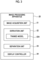
- FIG. 3 is a diagram showing a functional configuration of the image processing apparatus according to the first embodiment.
- the image processing apparatus 20 comprises an image acquisition unit 21, a derivation unit 22, a separation unit 23, and a display controller 24.
- the CPU 11 By executing the image processing program 12 by the CPU 11, the CPU 11 functions as the image acquisition unit 21, the derivation unit 22, the separation unit 23, and the display controller 24.
- the derivation unit 22 derives a running vector representing a running direction of the tubular structure included in the medical image G0 at each pixel of the tubular structure.
- the tubular structure is an artery and a vein. Therefore, the derivation unit 22 derives a running vector at each pixel in the blood vessel included in the medical image G0.
- the running vector represents a direction in which a blood vessel is present, and in the present embodiment, vectors pointing in the same direction are treated as running vectors in the same direction.
- two vectors pointing in opposite directions by 180 degrees that is, two vectors having the same value in a case where the cosine of an angle with respect to the reference direction is calculated, both point in the direction in which a tubular structure is present. Therefore, in the present embodiment, running vectors pointing in opposite directions by 180 degrees are also treated as running vectors in the same direction.
- the running vector is assumed to be a unit vector having a size of 1. In the present embodiment, running vectors pointing in opposite directions by 180 degrees are treated as running vectors in the same direction.
- the running vector and the direction of blood flow do not necessarily match.
- the direction of blood flow is opposite between the artery and the vein, but in the present embodiment, the running vectors are in the same direction.
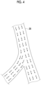
- Fig. 4 is a diagram showing running vectors.
- pixels in a blood vessel region 28 are indicated by black dots.
- running vectors are derived at all the pixels in the blood vessel region 28.
- the derivation unit 22 derives the running vector using a trained model 22A that derives the running vector at each pixel of the blood vessel from the medical image G0. In this case, the derivation unit 22 derives the running vectors for all the pixels of the medical image G0. Then, a blood vessel region is extracted from the medical image G0, and the running vector in the blood vessel region is specified.
- the derivation unit 22 extracts the blood vessel region from the medical image G0 without distinguishing between arteries and veins using a known method such as a Hessian filter, for example.
- a known method such as a Hessian filter
- various methods have been proposed, including a method disclosed in " A. F. Frangi et al. Multiscale vessel enhancement filtering, Proceedings of MICCAI, 130-137, 1998 .”
- the trained model 22A is, for example, a convolutional neural network (CNN), and is constructed by machine-learning the CNN using supervised training data.
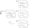
- Fig. 5 is a diagram showing supervised training data used to construct a trained model for deriving a running vector.
- supervised training data 30 consists of a medical image for training 31 including a blood vessel and correct answer data 32 to 34 representing a running vector at each pixel position in a blood vessel region included in the medical image for training 31. Since the image input to the trained model 22A in the present embodiment is a three-dimensional CT image, the medical image for training 31 is a three-dimensional CT image.
- the correct answer data 32 to 34 represent running vectors of each pixel (voxel) in an x direction, a y direction, and a z direction in the medical image for training 31.
- the correct answer data 32 to 34 may be derived from the medical image for training 31 using a method of analyzing the fluid inside the blood vessel by deep learning, as described in "Prediction of 3D Cardiovascular hemodynamics before and after coronary artery bypass surgery via deep learning, Gaoyang Li et al., COMMUNICATIONS BIOLOGY, 22 January 2021 ", for example.
- the correct answer data 32 to 34 may be derived by creating a graph structure passing through the center line for each of the artery and the vein, calculating a direction vector from the connection information of the nodes, and assigning the direction vector to the adjacent voxels as a correct vector.
- the derivation unit 22 may first extract a blood vessel region from the medical image G0 and derive the running vector only in the extracted blood vessel region.
- the medical image for training 31, a mask of the blood vessel region in the medical image for training 31, and correct answer data in the blood vessel region are used as supervised training data for training the trained model 22A.
- the medical image G0 and the mask of the blood vessel region extracted from the medical image G0 are input to the trained model 22A, and the running vector in the blood vessel region is output.
- the derivation unit 22 may derive the running vector for all the pixels of the medical image G0 or all the pixels in the blood vessel region, but may derive the running vector by thinning out every few pixels.
- the thinning-out interval of the pixels may be equal intervals, but in particular, in a case where the blood vessel region is extracted first, the thinning-out interval may be smaller at a position closer to the center of the blood vessel region, and the thinning-out interval may be larger at a position away from the center.
- the separation unit 23 separates arteries and veins using the running vectors derived by the derivation unit 22.
- the arteries and the veins are separated along running vectors.
- a plurality of tubular structures are separated by determining a likelihood that the same label is assigned to two adjacent pixels.
- Fig. 6 is a diagram for describing a likelihood that the same label is assigned to two adjacent pixels.
- a combination of a pixel Pa and a pixel Pb, a combination of a pixel Pc and a pixel Pd, and a combination of a pixel Pe and a pixel Pf are considered as shown in Fig. 6 .
- a direction vector Vab from the pixel Pa to the pixel Pb, a direction vector Vcd from the pixel Pc to the pixel Pd, and a direction vector Vef from the pixel Pe to the pixel Pf are set. Further, from the pixels Pa to Pf, running vectors Va to Vf are derived, respectively.
- angles ⁇ a and ⁇ b between the direction vector Vab and the running vectors Va and Vb, angles ⁇ c and ⁇ d between the direction vector Vcd and the running vectors Vc and Vd, and angles ⁇ e and ⁇ f between the direction vector Vef and the running vectors Ve and Vf the smaller the angle between the direction vector and at least one of the two running vectors, particularly each of the two running vectors, the higher the likelihood that the same label is assigned to two pixels.
- the separation unit 23 determines a likelihood that the same label is assigned to a combination of two pixels, and separates each pixel into an artery and a vein. For example, in a case where it is considered that each pixel is separated into an artery and a vein using a graph cut process, as the angle between the direction vector connecting the two pixels and the running vector at at least one of the two pixels is smaller, by reducing the energy of an edge connecting two pixels, the edge is not cut between the two pixels. A specific method thereof will be described below.
- the separation unit 23 separates the artery and the vein using a graph cut process by selecting a pixel group including N (> 3) pixels for which the running vectors are in the same direction or continuously change and which are adjacent in the direction of the running vectors, and minimizing an N-th order energy with labels of the pixels included in the pixel group as variables.
- the fact that the running vectors are continuous means that a change in the running vectors at the adjacent pixels is small such that the pixels can be smoothly connected along the direction of the running vectors, that is, there is a high likelihood that the same label is assigned to adjacent pixels as described above.
- the determination as to whether or not the change in the running vectors is small may be made by determining whether or not an angle between the running vectors for the two pixels and the direction vector connecting the two pixels is less than a predetermined threshold value and the change in direction of the two running vectors is less than a predetermined angle (for example, 45 degrees).
- the separation unit 23 minimizes the N-th order energy with the labels of the pixels included in the set pixel group as variables to separate the artery and the vein.
- the artery and the vein are separated using, for example, a higher-order graph cut method disclosed in JP2014-071716A .
- Fig. 8 is a diagram for describing a graph cut method.
- each pixel is used as a vertex, and two vertices s and t representing two labels to be separated from variables ⁇ x1, x2, ..., xn ⁇ , x ⁇ ⁇ 1,0 ⁇ , which correspond to each pixel of an image, are defined.
- each pixel has a vertex xi (or a vertex xj) corresponding to each pixel and two vertices s and t, and each of the vertex xi and the vertex xj is composed of an edge from the vertex s to the vertex xi, an edge from the vertex xi to the vertex t, and an edge between the vertices xi and xj corresponding to adjacent pixels.
- a primary energy is defined for the edge from the vertex s to the vertex xi and the edge from the vertex xi to the vertex t
- a secondary energy is defined for an edge connecting the vertices corresponding to the adjacent pixels.
- the energy is defined based on variables corresponding to each pixel.
- the graph cut is a method of defining such an energy and separating the vertices shown in Fig. 8 into a class of S and a class of T such that the energy is minimized.
- Fig. 8 shows that the fourth and sixth vertices from the left are separated into the class (variable is 1) of T, and the first to third and fifth vertices from the left are separated into the class of S (variable is 0).
- the N-th order energy is defined for the N (N > 3) pixel groups selected based on the running vector as described above, and the classes are separated such that the energy is minimized.
- the primary energy is a value that depends only on the label assigned to the pixel, and has a direct influence determined depending on which label is assigned to each pixel.
- the secondary energy is defined as energy to reflect prior knowledge as to how the labels assigned to adjacent pixels should be related to each other. In a case where all of variables corresponding to the N pixels included in the pixel group are 0 or all of the variables corresponding to the pixels included in the pixel group are 1, the N-th order energy is defined as energy to be smaller than in a case where all of the variables are not 0 and all of the variables are not 1.
- the separation unit 23 minimizes the N-th order energy and further defines the energy of each edge such that the label at which the sum of the primary energy, the secondary energy, and the N-th order energy is minimized corresponds to the minimum cut.
- the pixels in the artery and the pixels in the vein can be separated such that the blood vessels having the N pixels extending along the running vectors at all the positions are in the same class.
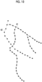
- a graph 40 in the blood vessel region included in the medical image G0 shown in Fig. 9 can be separated into a graph 41 of an artery shown by a solid line and a graph 42 of a vein shown by a broken line, as shown in Fig. 10 .
- the display controller 24 displays the arteries and veins separated by the separation unit 23 on the display 14 in an identifiable manner.
- Fig. 11 is a diagram showing a display screen of a separation result. Since the medical image G0 is a three-dimensional image, a three-dimensional projected image is displayed on the display 14 by a predetermined method such as volume rendering. In this case, the display controller 24 displays arteries and veins in different colors. In addition, in a display screen 45 shown in Fig. 11 , the difference in colors is shown by applying different hatching.
- Fig. 12 is a flowchart showing the process performed in the first embodiment.
- the image acquisition unit 21 acquires the medical image G0 from the image storage server 3 (Step ST1), and the derivation unit 22 derives a running vector representing a running direction of an artery and a vein at each pixel position of the artery and the vein based on the medical image G0 (Step ST2).
- the separation unit 23 separates the artery and the vein using the running vector (Step ST3)
- the display controller 24 displays the separation result (Step ST4), and the process ends.
- a plurality of tubular structures such as an artery and a vein, are separated using the running vectors representing the running directions of the plurality of tubular structures. Therefore, even in a case where the tubular structure is bent, the plurality of tubular structures can be separated along the running direction thereof. Therefore, it is possible to accurately separate a plurality of tubular structures included in the medical image G0.
- the image processing apparatus according to the second embodiment is different from that of the first embodiment in that the separation unit 23 selects a pixel group including N (> 3) pixels having the shortest weighted path based on a likelihood that the same label is assigned. Specifically, the separation unit 23 selects a pixel group including N (> 3) pixels having the smallest sum of weighted paths obtained by multiplying a weight based on a likelihood that the same label is assigned by a length of a path connecting each pixel and then adding the weight.
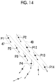
- Figs. 13 and 14 are diagrams for describing selection of pixel groups in the second embodiment.
- the separation unit 23 first derives in advance a likelihood that the same label as adjacent pixels is assigned to each pixel in the blood vessel region.
- the adjacent pixels are pixels in the vicinity of 9 or pixels in the vicinity of 27, but the adjacent pixels are not limited thereto.
- a likelihood it is sufficient that a smaller value is used in a case where the angle between the direction vector connecting the pixels and the running vector at each pixel is closer to 0 degrees or closer to 180 degrees that in a case where the angle is closer to 90 degrees.
- the separation unit 23 determines a likelihood that the same label as adjacent pixels is assigned in a predetermined range centered on the pixel P1. Then, a pixel having the highest likelihood and having the shortest path connected to the pixel P1 is specified. Specifically, a pixel having the smallest sum of weighted paths obtained by multiplying the likelihood by the length of the path from the pixel P1 is specified. In the running vector shown in Fig. 13 , it is assumed that a pixel P2 is specified with respect to the pixel P1. Next, the separation unit 23 determines a likelihood that the same label as adjacent pixels is assigned in a predetermined range centered on the pixel P2.
- a pixel having the highest likelihood and having the shortest path connected to the pixel P2 is specified in the same manner as described above.
- a pixel P3 is specified with respect to the pixel P2.
- the separation unit 23 repeats the same process to select a pixel group including N (for example, four) pixels having the shortest path to the pixel P1.
- the selected pixel group is a pixel group 47 including pixels P1 to P4 as shown in Fig. 14 .
- the selected pixel group is a pixel group 48 including pixels P11 to P14 as shown in Fig. 14 .
- the graph cut process after the pixel group is selected may be performed in the same manner as in the first embodiment. Accordingly, in the second embodiment, as in the first embodiment, even in a case where the tubular structure is bent, the plurality of tubular structures can be separated along the running direction thereof. Therefore, it is possible to accurately separate a plurality of tubular structures included in the medical image G0.
- the image processing apparatus according to the third embodiment is different from that of the first embodiment in that the derivation unit 22 derives a running vector at a plurality of pixels (referred to as center pixels) along the center of the blood vessel region extracted from the medical image G0, and the separation unit 23 derives a shortest path tree from an origin of a class representing each of the artery and the vein such that an angle formed by an edge connecting the plurality of center pixels and the running vector is minimized, and separates the artery and the vein such that the plurality of center pixels are in the same class as an origin having a closer path and a higher likelihood that the same label is assigned.
- center pixels a plurality of pixels along the center of the blood vessel region extracted from the medical image G0
- the separation unit 23 derives a shortest path tree from an origin of a class representing each of the artery and the vein such that an angle formed by an edge connecting the plurality of center pixels and the running vector is minimized, and separates the artery and the vein such that the plurality of center pixels are in the same
- Figs. 15A to 15E are diagrams for describing separation of arteries and veins in the third embodiment.
- the derivation unit 22 sets a plurality of center pixels at intervals along the center line of the blood vessel region as shown in Fig. 15A in the blood vessel region extracted from the medical image G0, and derives a running vector for each of the plurality of center pixels.
- the separation unit 23 sets a pixel P21 as the origin of the artery and a pixel P31 as the origin of the vein, and derives a shortest path tree from the pixel P21 and the pixel P31.
- a plurality of edges are set for the one center pixel in the shortest path tree.
- the separation unit 23 derives the artery and the vein by cutting the shortest path tree such that the plurality of center pixels are in the same class as an origin having a closer path and a higher likelihood that the same label is assigned.
- the energy of an edge connecting a center pixel for which a plurality of edges are set and a center pixel having the highest likelihood that the same label as the label assigned to the center pixel is assigned is reduced, and the energy of the other edges is set to be large. Accordingly, as shown in Fig. 15C , the edges in the direction along the running vector as indicated by a solid line are not cut, and the edges in the direction intersecting the running vector as indicated by a broken line are cut. Therefore, as shown in Fig.
- the shortest path tree can be separated into a graph 51 of an artery indicated by a solid line and a graph 52 of a vein indicated by a broken line. Then, the separation unit 23 extracts an artery region 53 and a vein region 54 in the medical image G0 by expanding a region of each of the graphs 51 and 52, as shown in Fig. 15E .
- the image processing apparatus according to the fourth embodiment is different from that of the first embodiment in that the separation unit 23 separates pixels other than pixels along the running vector into tubular structures different from each other. In other words, in the fourth embodiment, the pixels not along the running vector are not separated into the same tubular structure.
- the image processing apparatus separates each voxel of the medical image G0 into an artery and a vein using the trained model such that a boundary of the artery and the vein is derived between pixels other than pixels where the running vectors intersect each other, that is, between pixels where the running vectors do not intersect each other.
Landscapes
- Engineering & Computer Science (AREA)
- Theoretical Computer Science (AREA)
- Physics & Mathematics (AREA)
- General Physics & Mathematics (AREA)
- Computer Vision & Pattern Recognition (AREA)
- General Health & Medical Sciences (AREA)
- Health & Medical Sciences (AREA)
- Medical Informatics (AREA)
- Multimedia (AREA)
- Evolutionary Computation (AREA)
- Software Systems (AREA)
- Artificial Intelligence (AREA)
- Computing Systems (AREA)
- Databases & Information Systems (AREA)
- Quality & Reliability (AREA)
- Radiology & Medical Imaging (AREA)
- Nuclear Medicine, Radiotherapy & Molecular Imaging (AREA)
- Geometry (AREA)
- Spectroscopy & Molecular Physics (AREA)
- Vascular Medicine (AREA)
- Human Computer Interaction (AREA)
- Image Analysis (AREA)
- Apparatus For Radiation Diagnosis (AREA)
Claims (11)
- Bildverarbeitungsvorrichtung, die mindestens einen Prozessor (11) umfasst,
wobei der Prozessor so konfiguriert ist, dass er:an jedem Pixel von mehreren rohrförmigen Strukturen Laufvektoren, die Einheitsvektoren sind, die Richtungen, die von dem Pixel, in dem eine rohrförmige Struktur vorhanden ist, laufen, darstellen, auf der Grundlage eines medizinischen Bildes, das die mehreren rohrförmigen Strukturen enthält, ableitet; unddie mehreren rohrförmigen Strukturen entlang der Laufvektoren trennt;dadurch gekennzeichnet, dassder Prozessor so konfiguriert ist, dass er, auf der Grundlage eines Winkels, der durch einen Richtungsvektor von einem ersten Pixel zu einem zweiten Pixel und den Laufvektor an mindestens einem von dem ersten Pixel und dem zweiten Pixel gebildet wird, die Wahrscheinlichkeit, dass das gleiche Etikett dem ersten Pixel und dem zweiten Pixel zugewiesen wird, um die mehreren rohrförmigen Strukturen zu trennen, bestimmt, wobei je kleiner der Winkel ist, die Wahrscheinlichkeit umso größer ist, dass das gleiche Etikett den ersten und zweiten Pixeln zugewiesen wird. - Bildverarbeitungsvorrichtung nach Anspruch 1,
wobei der Prozessor so konfiguriert ist, dass er den Laufvektor unter Verwendung eines trainierten Modells zum Ableiten des Laufvektors an jedem Pixel der mehreren rohrförmigen Strukturen aus dem medizinischen Bild ableitet. - Bildverarbeitungsvorrichtung nach Anspruch 1 oder 2,
wobei der Prozessor so konfiguriert ist, dass er bei Trennen der mehreren rohrförmigen Strukturen unter Verwendung eines Graphenschnittprozesses durch Auswählen einer Pixelgruppe, die N (> 3) Pixel, für die die Laufvektoren in der gleichen Richtung sind oder sich kontinuierlich ändern, und die zueinander benachbart sind, enthält, und Minimieren einer Energie N-ter Ordnung mit Etiketten der in der Pixelgruppe enthaltenen Pixel als Variablen, wobei die Variablen, die durch 0 oder 1 dargestellt werden, die Energie N-ter Ordnung so einstellt, dass sie in einem Fall, in dem alle Variablen, die den in der Pixelgruppe enthaltenen Pixeln entsprechen, 0 sind oder alle Variablen, die den in der Pixelgruppe enthaltenen Pixeln entsprechen, 1 sind, niedriger als in einem Fall, in dem nicht alle Variablen 0 sind und nicht alle Variablen 1 sind, ist. - Bildverarbeitungsvorrichtung nach Anspruch 3,
wobei der Prozessor so konfiguriert ist, dass er bei Trennen der mehreren rohrförmigen Strukturen unter Verwendung eines Graphenschnittprozesses durch Auswählen einer Pixelgruppe, die N (> 3) Pixel mit einem kürzesten gewichteten Weg enthält, auf der Grundlage der Wahrscheinlichkeit, dass das gleiche Etikett zugewiesen wird, und Minimieren einer Energie N-ter Ordnung mit Etiketten der in der Pixelgruppe enthaltenen Pixel als Variablen, wobei die Variablen, die durch 0 oder 1 dargestellt werden, die Energie N-ter Ordnung so einstellt, dass sie in einem Fall, in dem alle Variablen, die den in der Pixelgruppe enthaltenen Pixeln entsprechen, 0 sind oder alle Variablen, die den in der Pixelgruppe enthaltenen Pixeln entsprechen, 1 sind, niedriger als in einem Fall, in dem nicht alle Variablen 0 sind und nicht alle Variablen 1 sind, ist. - Bildverarbeitungsvorrichtung nach Anspruch 1 oder 2,
wobei der Prozessor so konfiguriert ist, dass er:einen Laufvektor an mehreren Mittelpixeln entlang einer Mitte der mehreren rohrförmigen Strukturen ableitet;einen kürzesten Pfadbaum aus einem Ursprung einer Klasse, die jede der mehreren rohrförmigen Strukturen darstellt, so ableitet, dass ein Winkel, der durch eine Kante,die die mehreren Mittelpixel verbindet, und den Laufvektor gebildet wird, minimiert wird; unddie mehreren rohrförmigen Strukturen durch Schneiden des kürzesten Pfadbaums so trennt, dass die mehreren Mittelpixel in derselben Klasse wie ein Ursprung mit einem näheren Pfad und einer höheren Wahrscheinlichkeit, dass das gleiche Etikett zugewiesen wird, sind. - Bildverarbeitungsvorrichtung nach Anspruch 1 oder 2,
wobei der Prozessor so konfiguriert ist, dass er Pixel, die nicht Pixel entlang der Laufvektoren sind, in rohrförmige Strukturen, die voneinander verschieden sind, trennt. - Bildverarbeitungsvorrichtung nach Anspruch 6,
wobei der Prozessor so konfiguriert ist, dass er die mehreren rohrförmigen Strukturen so trennt, dass eine Grenze der mehreren rohrförmigen Strukturen zwischen anderen Pixeln als Pixeln, an denen die Laufvektoren einander schneiden, abgeleitet wird. - Bildverarbeitungsvorrichtung nach Anspruch 7,
wobei der Prozessor so konfiguriert ist, dass er die mehreren rohrförmigen Strukturen unter Verwendung eines trainierten Modells, bei dem maschinelles Lernen so durchgeführt wird, dass ein Verlust in einer Richtung in der die Laufvektoren kontinuierlich sind, zu minimieren, auf der Grundlage des medizinischen Bildes und der Laufvektoren trennt. - Bildverarbeitungsvorrichtung nach einem der Ansprüche 1 bis 8,
wobei die mehreren rohrförmigen Strukturen mindestens zwei von einer Arterie, einer Vene, einer Pfortader, einem Harnleiter und einem Nerv enthalten. - Bildverarbeitungsverfahren, umfassend:Ableiten, an jedem Pixel von mehreren rohrförmigen Strukturen, von Laufvektoren, die Einheitsvektoren sind, die Richtungen, die von dem Pixel, in dem eine rohrförmigen Struktur vorhanden ist, laufen, darstellen, auf der Grundlage eines medizinischen Bildes, das die mehreren rohrförmigen Strukturen enthält; undTrennen der mehreren rohrförmigen Strukturen entlang der Laufvektoren,wobei das Verfahren gekennzeichnet ist: durchUmfassen, auf der Grundlage eines Winkels, der durch einen Richtungsvektor von einem ersten Pixel zu einem zweiten Pixel und den Laufvektor an mindestens einem von dem ersten Pixel und dem zweiten Pixel gebildet wird, Bestimmen der Wahrscheinlichkeit, dass das gleiche Etikett dem ersten Pixel und dem zweiten Pixel zugewiesen wird, um die mehreren rohrförmigen Strukturen zu trennen, wobei je kleiner der Winkel ist, die Wahrscheinlichkeit umso größer ist, dass das gleiche Etikett den ersten und zweiten Pixeln zugewiesen wird.
- Computerlesbares Speichermedium, das ein Bildverarbeitungsprogramm speichert, das Anweisungen umfasst, die, wenn sie von einem Computer ausgeführt werden, den Computer veranlassen, durchzuführen:einen Schritt des Ableitens, an jedem Pixel von mehreren rohrförmigen Strukturen, von Laufvektoren, die Einheitsvektoren sind, die Richtungen, die von dem Pixel, in dem eine rohrförmige Struktur vorhanden ist, laufen, darstellen, auf der Grundlage eines medizinischen Bildes, das die mehreren rohrförmigen Strukturen enthält; undeinen Schritt des Trennens der mehreren rohrförmigen Strukturen entlang der Laufvektoren; undgekennzeichnet durcheinen Schritt des Bestimmens, auf der Grundlage eines Winkels, der durch einen Richtungsvektor von einem ersten Pixel zu einem zweiten Pixel und den Laufvektor an mindestens einem von dem ersten Pixel und dem zweiten Pixel gebildet wird, der Wahrscheinlichkeit, dass das gleiche Etikett dem ersten Pixel und dem zweiten Pixel zugewiesen wird, um die mehreren rohrförmigen Strukturen zu trennen, wobei je kleiner der Winkel ist, die Wahrscheinlichkeit umso größer ist, dass das gleiche Etikett den ersten und zweiten Pixeln zugewiesen wird.
Applications Claiming Priority (1)
| Application Number | Priority Date | Filing Date | Title |
|---|---|---|---|
| JP2022199948A JP2024085473A (ja) | 2022-12-15 | 2022-12-15 | 画像処理装置、方法およびプログラム |
Publications (2)
| Publication Number | Publication Date |
|---|---|
| EP4386665A1 EP4386665A1 (de) | 2024-06-19 |
| EP4386665B1 true EP4386665B1 (de) | 2025-07-02 |
Family
ID=89121625
Family Applications (1)
| Application Number | Title | Priority Date | Filing Date |
|---|---|---|---|
| EP23214590.4A Active EP4386665B1 (de) | 2022-12-15 | 2023-12-06 | Bildverarbeitungsvorrichtung, -verfahren und -programm |
Country Status (3)
| Country | Link |
|---|---|
| US (1) | US20240203093A1 (de) |
| EP (1) | EP4386665B1 (de) |
| JP (1) | JP2024085473A (de) |
Family Cites Families (4)
| Publication number | Priority date | Publication date | Assignee | Title |
|---|---|---|---|---|
| US9042611B2 (en) * | 2010-01-29 | 2015-05-26 | Mayo Foundation For Medical Education And Research | Automated vascular region separation in medical imaging |
| JP5559642B2 (ja) * | 2010-08-30 | 2014-07-23 | 富士フイルム株式会社 | 手術支援装置、手術支援方法および手術支援プログラム |
| JP5894514B2 (ja) | 2012-09-28 | 2016-03-30 | 富士フイルム株式会社 | 画像処理装置、画像処理プログラムおよび画像処理装置の動作方法 |
| GB202101908D0 (en) * | 2021-02-11 | 2021-03-31 | Axial Medical Printing Ltd | Axial3D pathology |
-
2022
- 2022-12-15 JP JP2022199948A patent/JP2024085473A/ja active Pending
-
2023
- 2023-12-05 US US18/530,170 patent/US20240203093A1/en active Pending
- 2023-12-06 EP EP23214590.4A patent/EP4386665B1/de active Active
Also Published As
| Publication number | Publication date |
|---|---|
| EP4386665A1 (de) | 2024-06-19 |
| JP2024085473A (ja) | 2024-06-27 |
| US20240203093A1 (en) | 2024-06-20 |
Similar Documents
| Publication | Publication Date | Title |
|---|---|---|
| US11861829B2 (en) | Deep learning based medical image detection method and related device | |
| US11751832B2 (en) | CTA large vessel occlusion model | |
| US20250285265A1 (en) | Systems and methods for detecting structures in 3d images | |
| US11216950B2 (en) | Method and system for automatically segmenting blood vessel in medical image by using machine learning and image processing algorithm | |
| Al Arif et al. | Fully automatic cervical vertebrae segmentation framework for X-ray images | |
| CN109493347B (zh) | 在图像中对稀疏分布的对象进行分割的方法和系统 | |
| KR102458324B1 (ko) | 학습 모델을 이용한 데이터 처리 방법 | |
| Cuadros Linares et al. | Mandible and skull segmentation in cone beam computed tomography using super-voxels and graph clustering | |
| Meng et al. | Regression of instance boundary by aggregated CNN and GCN | |
| JP7456928B2 (ja) | 胸部x線画像の異常表示制御方法、異常表示制御プログラム、異常表示制御装置、及びサーバ装置 | |
| CN113724185A (zh) | 用于图像分类的模型处理方法、装置及存储介质 | |
| CN113962957A (zh) | 医学图像处理方法、骨骼图像处理方法、装置、设备 | |
| La Rosa | A deep learning approach to bone segmentation in CT scans | |
| JP2022546303A (ja) | 管状フィーチャのセグメント化 | |
| WO2022163513A1 (ja) | 学習済みモデルの生成方法、機械学習システム、プログラムおよび医療画像処理装置 | |
| US12288328B2 (en) | Blood flow field estimation apparatus, learning apparatus, blood flow field estimation method, and program | |
| CN115330753A (zh) | 椎骨识别方法、装置、设备及存储介质 | |
| EP4386665B1 (de) | Bildverarbeitungsvorrichtung, -verfahren und -programm | |
| CN112884706B (zh) | 一种基于神经网络模型的图像评估系统和相关产品 | |
| KR102768829B1 (ko) | 기계 학습 모델 기반의 이미지 분석을 통한 의료 영상 분류 방법 | |
| CN116205935A (zh) | 医学图像的分割方法、装置、设备、存储介质及程序产品 | |
| KR20220133834A (ko) | 학습 모델을 이용한 데이터 처리 방법 | |
| JP7105918B2 (ja) | 領域特定装置、方法およびプログラム | |
| Marie et al. | Segmentation of kidneys deformed by nephroblastoma using case-based reasoning | |
| WO2022129626A1 (en) | Continual-learning and transfer-learning based on-site adaptation of image classification and object localization modules |
Legal Events
| Date | Code | Title | Description |
|---|---|---|---|
| PUAI | Public reference made under article 153(3) epc to a published international application that has entered the european phase |
Free format text: ORIGINAL CODE: 0009012 |
|
| STAA | Information on the status of an ep patent application or granted ep patent |
Free format text: STATUS: THE APPLICATION HAS BEEN PUBLISHED |
|
| AK | Designated contracting states |
Kind code of ref document: A1 Designated state(s): AL AT BE BG CH CY CZ DE DK EE ES FI FR GB GR HR HU IE IS IT LI LT LU LV MC ME MK MT NL NO PL PT RO RS SE SI SK SM TR |
|
| STAA | Information on the status of an ep patent application or granted ep patent |
Free format text: STATUS: REQUEST FOR EXAMINATION WAS MADE |
|
| 17P | Request for examination filed |
Effective date: 20241218 |
|
| GRAP | Despatch of communication of intention to grant a patent |
Free format text: ORIGINAL CODE: EPIDOSNIGR1 |
|
| STAA | Information on the status of an ep patent application or granted ep patent |
Free format text: STATUS: GRANT OF PATENT IS INTENDED |
|
| RIC1 | Information provided on ipc code assigned before grant |
Ipc: G06V 10/82 20220101ALI20250228BHEP Ipc: G06T 7/11 20170101ALI20250228BHEP Ipc: G06V 40/14 20220101ALI20250228BHEP Ipc: G06T 7/162 20170101ALI20250228BHEP Ipc: G06T 7/00 20170101AFI20250228BHEP |
|
| INTG | Intention to grant announced |
Effective date: 20250318 |
|
| RAP3 | Party data changed (applicant data changed or rights of an application transferred) |
Owner name: FUJIFILM CORPORATION |
|
| GRAS | Grant fee paid |
Free format text: ORIGINAL CODE: EPIDOSNIGR3 |
|
| GRAA | (expected) grant |
Free format text: ORIGINAL CODE: 0009210 |
|
| STAA | Information on the status of an ep patent application or granted ep patent |
Free format text: STATUS: THE PATENT HAS BEEN GRANTED |
|
| AK | Designated contracting states |
Kind code of ref document: B1 Designated state(s): AL AT BE BG CH CY CZ DE DK EE ES FI FR GB GR HR HU IE IS IT LI LT LU LV MC ME MK MT NL NO PL PT RO RS SE SI SK SM TR |
|
| REG | Reference to a national code |
Ref country code: GB Ref legal event code: FG4D |
|
| REG | Reference to a national code |
Ref country code: CH Ref legal event code: EP |
|
| REG | Reference to a national code |
Ref country code: DE Ref legal event code: R096 Ref document number: 602023004526 Country of ref document: DE |
|
| REG | Reference to a national code |
Ref country code: IE Ref legal event code: FG4D |
|
| REG | Reference to a national code |
Ref country code: NL Ref legal event code: MP Effective date: 20250702 |
|
| PG25 | Lapsed in a contracting state [announced via postgrant information from national office to epo] |
Ref country code: PT Free format text: LAPSE BECAUSE OF FAILURE TO SUBMIT A TRANSLATION OF THE DESCRIPTION OR TO PAY THE FEE WITHIN THE PRESCRIBED TIME-LIMIT Effective date: 20251103 |
|
| PG25 | Lapsed in a contracting state [announced via postgrant information from national office to epo] |
Ref country code: NL Free format text: LAPSE BECAUSE OF FAILURE TO SUBMIT A TRANSLATION OF THE DESCRIPTION OR TO PAY THE FEE WITHIN THE PRESCRIBED TIME-LIMIT Effective date: 20250702 |
|
| REG | Reference to a national code |
Ref country code: AT Ref legal event code: MK05 Ref document number: 1810126 Country of ref document: AT Kind code of ref document: T Effective date: 20250702 |
|
| PG25 | Lapsed in a contracting state [announced via postgrant information from national office to epo] |
Ref country code: IS Free format text: LAPSE BECAUSE OF FAILURE TO SUBMIT A TRANSLATION OF THE DESCRIPTION OR TO PAY THE FEE WITHIN THE PRESCRIBED TIME-LIMIT Effective date: 20251102 |
|
| PGFP | Annual fee paid to national office [announced via postgrant information from national office to epo] |
Ref country code: DE Payment date: 20251028 Year of fee payment: 3 |
|
| PG25 | Lapsed in a contracting state [announced via postgrant information from national office to epo] |
Ref country code: NO Free format text: LAPSE BECAUSE OF FAILURE TO SUBMIT A TRANSLATION OF THE DESCRIPTION OR TO PAY THE FEE WITHIN THE PRESCRIBED TIME-LIMIT Effective date: 20251002 |
|
| REG | Reference to a national code |
Ref country code: LT Ref legal event code: MG9D |
|
| PG25 | Lapsed in a contracting state [announced via postgrant information from national office to epo] |
Ref country code: AT Free format text: LAPSE BECAUSE OF FAILURE TO SUBMIT A TRANSLATION OF THE DESCRIPTION OR TO PAY THE FEE WITHIN THE PRESCRIBED TIME-LIMIT Effective date: 20250702 |
|
| PG25 | Lapsed in a contracting state [announced via postgrant information from national office to epo] |
Ref country code: FI Free format text: LAPSE BECAUSE OF FAILURE TO SUBMIT A TRANSLATION OF THE DESCRIPTION OR TO PAY THE FEE WITHIN THE PRESCRIBED TIME-LIMIT Effective date: 20250702 |
|
| PG25 | Lapsed in a contracting state [announced via postgrant information from national office to epo] |
Ref country code: HR Free format text: LAPSE BECAUSE OF FAILURE TO SUBMIT A TRANSLATION OF THE DESCRIPTION OR TO PAY THE FEE WITHIN THE PRESCRIBED TIME-LIMIT Effective date: 20250702 |
|
| PG25 | Lapsed in a contracting state [announced via postgrant information from national office to epo] |
Ref country code: GR Free format text: LAPSE BECAUSE OF FAILURE TO SUBMIT A TRANSLATION OF THE DESCRIPTION OR TO PAY THE FEE WITHIN THE PRESCRIBED TIME-LIMIT Effective date: 20251003 |
|
| PG25 | Lapsed in a contracting state [announced via postgrant information from national office to epo] |
Ref country code: CZ Free format text: LAPSE BECAUSE OF FAILURE TO SUBMIT A TRANSLATION OF THE DESCRIPTION OR TO PAY THE FEE WITHIN THE PRESCRIBED TIME-LIMIT Effective date: 20250702 Ref country code: SE Free format text: LAPSE BECAUSE OF FAILURE TO SUBMIT A TRANSLATION OF THE DESCRIPTION OR TO PAY THE FEE WITHIN THE PRESCRIBED TIME-LIMIT Effective date: 20250702 |
|
| PG25 | Lapsed in a contracting state [announced via postgrant information from national office to epo] |
Ref country code: LV Free format text: LAPSE BECAUSE OF FAILURE TO SUBMIT A TRANSLATION OF THE DESCRIPTION OR TO PAY THE FEE WITHIN THE PRESCRIBED TIME-LIMIT Effective date: 20250702 |
|
| PG25 | Lapsed in a contracting state [announced via postgrant information from national office to epo] |
Ref country code: BG Free format text: LAPSE BECAUSE OF FAILURE TO SUBMIT A TRANSLATION OF THE DESCRIPTION OR TO PAY THE FEE WITHIN THE PRESCRIBED TIME-LIMIT Effective date: 20250702 Ref country code: PL Free format text: LAPSE BECAUSE OF FAILURE TO SUBMIT A TRANSLATION OF THE DESCRIPTION OR TO PAY THE FEE WITHIN THE PRESCRIBED TIME-LIMIT Effective date: 20250702 |
|
| PG25 | Lapsed in a contracting state [announced via postgrant information from national office to epo] |
Ref country code: RS Free format text: LAPSE BECAUSE OF FAILURE TO SUBMIT A TRANSLATION OF THE DESCRIPTION OR TO PAY THE FEE WITHIN THE PRESCRIBED TIME-LIMIT Effective date: 20251002 |
|
| PG25 | Lapsed in a contracting state [announced via postgrant information from national office to epo] |
Ref country code: ES Free format text: LAPSE BECAUSE OF FAILURE TO SUBMIT A TRANSLATION OF THE DESCRIPTION OR TO PAY THE FEE WITHIN THE PRESCRIBED TIME-LIMIT Effective date: 20250702 |
|
| PG25 | Lapsed in a contracting state [announced via postgrant information from national office to epo] |
Ref country code: RO Free format text: LAPSE BECAUSE OF FAILURE TO SUBMIT A TRANSLATION OF THE DESCRIPTION OR TO PAY THE FEE WITHIN THE PRESCRIBED TIME-LIMIT Effective date: 20250702 |
|
| PG25 | Lapsed in a contracting state [announced via postgrant information from national office to epo] |
Ref country code: SM Free format text: LAPSE BECAUSE OF FAILURE TO SUBMIT A TRANSLATION OF THE DESCRIPTION OR TO PAY THE FEE WITHIN THE PRESCRIBED TIME-LIMIT Effective date: 20250702 |
|
| PG25 | Lapsed in a contracting state [announced via postgrant information from national office to epo] |
Ref country code: DK Free format text: LAPSE BECAUSE OF FAILURE TO SUBMIT A TRANSLATION OF THE DESCRIPTION OR TO PAY THE FEE WITHIN THE PRESCRIBED TIME-LIMIT Effective date: 20250702 |
|
| PG25 | Lapsed in a contracting state [announced via postgrant information from national office to epo] |
Ref country code: IT Free format text: LAPSE BECAUSE OF FAILURE TO SUBMIT A TRANSLATION OF THE DESCRIPTION OR TO PAY THE FEE WITHIN THE PRESCRIBED TIME-LIMIT Effective date: 20250702 |
|
| PG25 | Lapsed in a contracting state [announced via postgrant information from national office to epo] |
Ref country code: EE Free format text: LAPSE BECAUSE OF FAILURE TO SUBMIT A TRANSLATION OF THE DESCRIPTION OR TO PAY THE FEE WITHIN THE PRESCRIBED TIME-LIMIT Effective date: 20250702 Ref country code: SK Free format text: LAPSE BECAUSE OF FAILURE TO SUBMIT A TRANSLATION OF THE DESCRIPTION OR TO PAY THE FEE WITHIN THE PRESCRIBED TIME-LIMIT Effective date: 20250702 |