EP4386802A1 - Vakuum-leistungsschalter - Google Patents
Vakuum-leistungsschalter Download PDFInfo
- Publication number
- EP4386802A1 EP4386802A1 EP22855620.5A EP22855620A EP4386802A1 EP 4386802 A1 EP4386802 A1 EP 4386802A1 EP 22855620 A EP22855620 A EP 22855620A EP 4386802 A1 EP4386802 A1 EP 4386802A1
- Authority
- EP
- European Patent Office
- Prior art keywords
- housing
- arc extinguishing
- contact
- vacuum arc
- circuit breaker
- Prior art date
- Legal status (The legal status is an assumption and is not a legal conclusion. Google has not performed a legal analysis and makes no representation as to the accuracy of the status listed.)
- Pending
Links
Images


Classifications
-
- H—ELECTRICITY
- H01—ELECTRIC ELEMENTS
- H01H—ELECTRIC SWITCHES; RELAYS; SELECTORS; EMERGENCY PROTECTIVE DEVICES
- H01H33/00—High-tension or heavy-current switches with arc-extinguishing or arc-preventing means
- H01H33/60—Switches wherein the means for extinguishing or preventing the arc do not include separate means for obtaining or increasing flow of arc-extinguishing fluid
- H01H33/66—Vacuum switches
- H01H33/666—Operating arrangements
-
- H—ELECTRICITY
- H01—ELECTRIC ELEMENTS
- H01H—ELECTRIC SWITCHES; RELAYS; SELECTORS; EMERGENCY PROTECTIVE DEVICES
- H01H1/00—Contacts
- H01H1/0015—Means for testing or for inspecting contacts, e.g. wear indicator
-
- H—ELECTRICITY
- H01—ELECTRIC ELEMENTS
- H01H—ELECTRIC SWITCHES; RELAYS; SELECTORS; EMERGENCY PROTECTIVE DEVICES
- H01H1/00—Contacts
- H01H1/50—Means for increasing contact pressure, preventing vibration of contacts, holding contacts together after engagement, or biasing contacts to the open position
-
- H—ELECTRICITY
- H01—ELECTRIC ELEMENTS
- H01H—ELECTRIC SWITCHES; RELAYS; SELECTORS; EMERGENCY PROTECTIVE DEVICES
- H01H33/00—High-tension or heavy-current switches with arc-extinguishing or arc-preventing means
- H01H33/60—Switches wherein the means for extinguishing or preventing the arc do not include separate means for obtaining or increasing flow of arc-extinguishing fluid
- H01H33/66—Vacuum switches
- H01H33/6606—Terminal arrangements
-
- H—ELECTRICITY
- H01—ELECTRIC ELEMENTS
- H01H—ELECTRIC SWITCHES; RELAYS; SELECTORS; EMERGENCY PROTECTIVE DEVICES
- H01H1/00—Contacts
- H01H1/50—Means for increasing contact pressure, preventing vibration of contacts, holding contacts together after engagement, or biasing contacts to the open position
- H01H1/502—Means for increasing contact pressure, preventing vibration of contacts, holding contacts together after engagement, or biasing contacts to the open position the action of the contact pressure spring becoming active only after engagement of the contacts
-
- H—ELECTRICITY
- H01—ELECTRIC ELEMENTS
- H01H—ELECTRIC SWITCHES; RELAYS; SELECTORS; EMERGENCY PROTECTIVE DEVICES
- H01H11/00—Apparatus or processes specially adapted for the manufacture of electric switches
- H01H11/0062—Testing or measuring non-electrical properties of switches, e.g. contact velocity
-
- H—ELECTRICITY
- H01—ELECTRIC ELEMENTS
- H01H—ELECTRIC SWITCHES; RELAYS; SELECTORS; EMERGENCY PROTECTIVE DEVICES
- H01H33/00—High-tension or heavy-current switches with arc-extinguishing or arc-preventing means
- H01H33/60—Switches wherein the means for extinguishing or preventing the arc do not include separate means for obtaining or increasing flow of arc-extinguishing fluid
- H01H33/66—Vacuum switches
- H01H33/662—Housings or protective screens
- H01H33/66207—Specific housing details, e.g. sealing, soldering or brazing
- H01H2033/6623—Details relating to the encasing or the outside layers of the vacuum switch housings
-
- H—ELECTRICITY
- H01—ELECTRIC ELEMENTS
- H01H—ELECTRIC SWITCHES; RELAYS; SELECTORS; EMERGENCY PROTECTIVE DEVICES
- H01H33/00—High-tension or heavy-current switches with arc-extinguishing or arc-preventing means
- H01H33/60—Switches wherein the means for extinguishing or preventing the arc do not include separate means for obtaining or increasing flow of arc-extinguishing fluid
- H01H33/66—Vacuum switches
- H01H33/666—Operating arrangements
- H01H2033/6665—Details concerning the mounting or supporting of the individual vacuum bottles
-
- H—ELECTRICITY
- H01—ELECTRIC ELEMENTS
- H01H—ELECTRIC SWITCHES; RELAYS; SELECTORS; EMERGENCY PROTECTIVE DEVICES
- H01H33/00—High-tension or heavy-current switches with arc-extinguishing or arc-preventing means
- H01H33/60—Switches wherein the means for extinguishing or preventing the arc do not include separate means for obtaining or increasing flow of arc-extinguishing fluid
- H01H33/66—Vacuum switches
- H01H33/666—Operating arrangements
- H01H2033/6667—Details concerning lever type driving rod arrangements
-
- H—ELECTRICITY
- H01—ELECTRIC ELEMENTS
- H01H—ELECTRIC SWITCHES; RELAYS; SELECTORS; EMERGENCY PROTECTIVE DEVICES
- H01H33/00—High-tension or heavy-current switches with arc-extinguishing or arc-preventing means
- H01H33/02—Details
- H01H33/027—Integrated apparatus for measuring current or voltage
Definitions
- the present utility model relates to the technical field of control and protection of electrical equipment, and relates in particular to a vacuum circuit breaker.
- circuit breaker In the new-energy wind power industry, the product demand on low-voltage circuit breakers has been upgraded to an operating voltage of AC 1150 V/1500 V. At the same time, the circuit breaker is required to have a long service life. In addition, in high-polluting industries such as coal mines and oil gas, it is also desirable that circuit breaker products can realize zero flashover to ensure the safety of operators, circuits and electrical equipment in flammable and explosive environments.
- the present utility model aims to provide a vacuum circuit breaker capable of solving at least part of the above problems.
- a vacuum circuit breaker comprising an operating mechanism.
- the vacuum circuit breaker further comprises a plurality of vacuum arc extinguishing modules, the operating mechanism is connected to and drives each of the vacuum arc extinguishing modules, and each of the vacuum arc extinguishing modules comprises: a housing; a vacuum arc extinguishing chamber, accommodated in the housing and having a stationary contact and a movable contact disposed opposite to each other; and a contact support assembly, accommodated in the housing and connected to the movable contact of the vacuum arc extinguishing chamber.
- the operating mechanism is connected to and drives the contact support assembly.
- An inner wall of the housing is provided with recesses and protrusions to match the vacuum arc extinguishing chamber and the contact support assembly, and is provided with connection openings corresponding to the stationary contact, the movable contact and the contact support assembly.
- each of the vacuum arc extinguishing modules has a linkage mechanism connected to the contact support assembly, the operating mechanism is connected to and drives the linkage mechanism of each of the vacuum arc extinguishing modules, and the connection openings of the housing comprise a first connection opening through which the linkage mechanism passes.
- the stationary contact of the vacuum arc extinguishing chamber is connected to a first connection terminal, and the connection openings of the housing comprise a second connection opening aligned with the first connection terminal.
- a coil is arranged at the first connection terminal, the inner wall of the housing has a recess for accommodating the coil, and the second connection opening is formed at the bottom of the recess.
- the movable contact of the vacuum arc extinguishing chamber is connected to a second connection terminal by a flexible connector, and the connection openings of the housing comprise a third connection opening aligned with the second connection terminal.
- the inner wall of the housing is provided with a ring extending along the perimeter of the housing, and the vacuum arc extinguishing chamber is surrounded by the ring.
- the housing comprises at least two housing portions that are detachably connected, and the recesses and protrusions are defined by combining the at least two housing portions.
- the vacuum arc extinguishing module is prefabricated.
- the contact support assembly comprises: a support; a contact spring, supported by the support; a movable member, connected to and moving along with the contact spring and having a wear indication portion; and a linkage, connected to the movable member, and provided with an end portion connected to the movable contact of the vacuum arc extinguishing chamber.
- the position of the movable member relative to the linkage is arranged in such a way that during closing of the movable contact and the stationary contact, a change in the position of the wear indication portion is identifiable when the movable contact and/or the stationary contact reaches a predetermined wear thickness value.
- the movable member further has an installation indication portion, and the installation indication portion is located away from the support relative to the wear indication portion.
- first, first one, second, and second one and similar terms used in the present utility model do not indicate any sequence, number, or importance in the present utility model, and are used only to distinguish one component from other components.
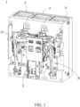
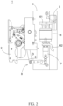
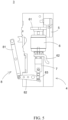
- FIGs. 1 to 3 show schematic views of a vacuum circuit breaker 1 according to the present utility model.
- the vacuum circuit breaker 1 includes an operating mechanism 2 and a plurality of vacuum arc extinguishing modules 3 driven by the operating mechanism 2 to achieve opening and closing.
- Three vacuum arc extinguishing modules 3 are shown in the figures, but those skilled in the art would appreciate that the vacuum arc extinguishing modules 3 are prefabricated and that during on-site installation in the working environment of the vacuum circuit breaker, a desired number of prefabricated vacuum arc extinguishing modules 3 can be connected in parallel to the operating mechanism 2 as required, and the number may be two or more, such as four, five, six or more.
- a main shaft 21 of the operating mechanism 2 may be operated to rotate about its own central axis, so as to drive a linkage mechanism 8 of each of the vacuum arc extinguishing modules 3 connected to the main shaft 21, thereby driving stationary and movable contacts of each of the vacuum arc extinguishing chambers 3 to close or open.
- a connecting lever 22 is sleeved on the main shaft 21 of the operating mechanism 2, and the rotation of the main shaft 21 can drive the connecting lever 22 to rotate synchronously.
- the connecting lever 22 is pivotally connected to a first rod 81 of the linkage mechanism 8, the first rod 81 is pivotally connected to a second rod 82, the second rod 82 is pivotally connected to a third rod 83, and the third rod 83 is pivotally connected to a contact support assembly 7 of a vacuum arc extinguishing chamber 6 from below (described in detail below), thereby controlling opening or closing of movable and stationary contacts within the vacuum arc extinguishing chamber 6.
- a contact support assembly 7 of a vacuum arc extinguishing chamber 6 from below (described in detail below)
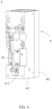
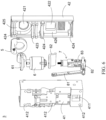
- FIGs. 4 to 6 schematically show an example of one vacuum arc extinguishing module 3 according to the present utility model.
- the vacuum arc extinguishing chamber 6 and the contact support assembly 7 are sealed in a housing 4.
- An inner wall of the housing 4 is provided with recesses and protrusions in order to match the accommodated components.
- the housing 4 is assembled from two or more housing portions. In the illustrated embodiment, the housing 4 consisting of two housing portions, i.e., a first housing portion 41 and a second housing portion 42, is described as an example.
- the first housing portion 41 and the second housing portion 42 may also be regarded as a front housing portion and a rear housing portion. As shown in FIG. 5 , for ease of assembly, the first housing portion 41 and the second housing portion 42 are provided with corresponding assembly holes 412 and corresponding assembly holes 424, respectively. After fitting the first housing portion 41 with the second housing portion 42, the first housing portion 41 and the second housing portion 42 are joined together by inserting a connecting member, such as a bolt or pin, into an assembly hole 412 and an assembly hole 424 aligned with each other.
- a connecting member such as a bolt or pin
- first housing portion 41 and the second housing portion 42 may be integrally made from a plastic material.
- first housing portion and the second housing portion may be provided with recessed and protruding positioning structures matching each other.
- a protruding portion is formed on the first housing portion, while a recessed portion that can accommodate the protruding portion is formed on the second housing portion.
- the protruding portion may also be formed on the second housing portion and the recessed portion is formed on the first housing portion.
- the vacuum arc extinguishing chamber 6 and the contact support assembly 7 are accommodated in the housing 4.
- the vacuum arc extinguishing chamber 6 includes a housing body, and a movable contact and a stationary contact (not shown) accommodated in the housing body.
- the contact support assembly 7 is connected to the movable contact, and the operating mechanism 2 can operate the contact support assembly 7 by means of the linkage mechanism 8, so as to further drive the movable contact to move toward or away from the stationary contact.
- the housing 4, such as the first housing portion 41, is provided with a first connection opening 411 at a position corresponding to the contact support assembly 7, so that the third rod 83 of the linkage mechanism 8 can pass through the first connection opening and connect to the contact support assembly 7.
- FIG. 7 illustrates an example of the contact support assembly 7.
- a connecting shaft 71 is installed at a support 72.
- the connecting shaft 71 is pivotally connected to the third rod 83 of the linkage mechanism 8.
- a sleeve tube 77 is supported on the support 72.
- a contact spring 78 is arranged within the sleeve tube 77.
- the contact spring 78 supports a movable member 75, and provides to the movable member 75 a pushing force in a direction that faces away from the support 72 (i.e. a direction pointing to the movable contact within the vacuum arc extinguishing chamber).
- a linkage 73 passes through the support 72, the contact spring 78, and the movable member 75, and the linkage 73 is connected to the movable member 75.
- the linkage 73 is not movable relative to the movable member 75, or at least the movable member 75 cannot move in the axial direction of the linkage 73, so that the movement of the movable member 75 (under the pushing force of the contact spring 78) drives the linkage 73 to move synchronously.
- One end of the linkage 73 extends out of a side of the support 72 facing away from the sleeve tube 77 and is provided with a flange 732.
- the dimension of the flange 732 is larger than that of an aperture of the support 72 through which the linkage 73 passes, thereby preventing detachment of the linkage 73 from the support 72 during movement.
- the other end of the linkage 73 extends out of a side of the movable member 75 facing away from the support 72, and serves as an end portion 731 connecting to the movable contact within the vacuum arc extinguishing chamber 6.
- a screw is used as the linkage 73, and a nut in threaded connection to the linkage 73 is used as the flange 732.
- the movable member 75 is adaptively provided with an inner thread mating with an outer thread of the screw, so that during assembly, the position of the movable member can be adjusted in the axial direction of the linkage 73. This adjustment is continuous, and the movable member can be adjusted to a suitable position and then fixed relative to the linkage 73.
- the movable member may be tightly sleeved on the linkage.
- An installation indication portion 751 and a wear indication portion 752 are provided at the outer circumference of the movable member 75.
- each of the installation indication portion 751 and the wear indication portion 752 is configured to be an indication line extending in a circumferential direction of the movable member 75.
- the installation indication portion 751 is closer to the end portion 731 of the linkage 73 connecting to the movable contact than the wear indication portion 752.
- the installation indication portion 751 and the wear indication portion 752 may have other forms, such as an image marker, a text marker, a scale marker, a color marker, or a combination of at least two of the forms, etc.
- An insulating sleeve 79 is further sleeved on the linkage 73.
- the insulating sleeve 79 may be a heat shrink tube sleeved on the linkage 73 and passing through the support 72 and the contact spring 78.
- the insulating sleeve may be sleeved on the linkage 73, and be provided with a radially extending flange at a position proximate to one end. The insulating sleeve passes through the support 72 and the contact spring 78 and is placed on the support by means of the radially extending flange, such that the support supports the insulating sleeve.
- a first insulating pad 74 may further be provided between a side of the support 72 facing away from the sleeve tube 77 and the flange 732 on the linkage 73.
- the first insulating pad 74 is sleeved on the linkage 73.
- a second insulating pad 76 may be arranged on a side surface of the movable member 75 that faces a contact connection end 421 of the linkage 73.
- the second insulating pad 76 is sleeved on the linkage 73.
- the installation indication portion 751 of the movable member 75 is exposed outside of the sleeve tube 77.
- An operator determines that the contact support assembly 7 is properly installed based on the visible or detectable installation indication portion 751, thereby determining the movement stroke of the contact spring.
- the wear indication portion 752 is not visible or detectable by the operator since the wear indication portion is located within the sleeve tube 77.
- the installation indication portion 751 of the movable member 75 moves away from the upper edge of the sleeve tube 77 due to a larger stroke of the connecting rod 73, while the wear indication portion 752 is exposed outside of the sleeve tube 77.
- the operator identifies a change in position of the wear indication portion (relative to the sleeve tube) based on the fact that the wear indication portion 752 is visible or detectable, thereby determining that the wear thickness of the movable and stationary contacts has reached a predetermined value.
- the movable contact of the vacuum arc extinguishing chamber 6 is connected to and driven by the contact support assembly 7, and the stationary contact is connected to a first connection terminal 61, and a coil 5 is arranged at the first connection terminal 61.
- the coil 5 surrounds a portion of the first connection terminal 61, and said portion of the first connection terminal 61 is proximate to an inner wall of the second housing portion 42 of the housing 4.
- the housing 4, such as the second housing portion 42, is provided with a second connection opening 421 at a position corresponding to the first connection terminal 61, so that a wire can pass through the second connection opening and connect to the first connection terminal 61.
- a recess 425 is provided on the inner wall of the second housing portion 42 of the housing 4 and is used to accommodate the coil.
- the shape of the recess may match the shape of the coil 5 so that the coil 5 is stably installed within the housing 4.
- the second connection opening 421 is correspondingly formed at the bottom of the recess 425.
- the flexible connector 62 may be sleeved on the linkage 73 of the contact support assembly 7.
- the housing 4, such as the second housing portion 42, is provided with a third connection opening 422 at a position corresponding to the flexible connector,so that the second connection terminal or a wire can pass through the third connection opening and connect to the flexible connector 62.
- the second housing portion 42 may be provided with a protrusion portion 426 protruding toward the flexible connector 63 at a position corresponding to the third connection opening 422, the third connection opening 422 passes through the protrusion portion 426, and the second connection terminal can be accommodated in the third connection opening 422 and connected to the flexible connector 62.
- the inner wall of the housing 4 is further integrally provided with a raised ring 423 that extends along the perimeter of the housing 4.
- the side surface of the ring 423 toward the vacuum arc extinguishing chamber 6 is a concave arc surface matching the outer periphery of the vacuum arc extinguishing chamber.
- the vacuum arc extinguishing chamber is surrounded and held by the ring such that horizontal movement of the vacuum arc extinguishing chamber is limited.
- the ring may be defined by combining a plurality of housing portions of the housing 4 together. For example, as shown in FIG. 6 , each of the first housing portion 41 and the second housing portion 42 is integrally provided with a half-ring, and after the two portions are combined together, a complete ring is formed.
- the vacuum arc extinguishing chamber and a series of components such as the support assembly are pre-sealed in a frame-type housing, so as to prefabricate a single small-sized vacuum arc extinguishing modular unit while retaining the zero flashover feature of the vacuum arc extinguishing chamber.
- Each modular unit has a reduced size and a neat appearance. After a required number of vacuum arc extinguishing modular units are connected in parallel to an operating mechanism, the overall structure of the vacuum circuit breaker is compact and the occupied space is small.
- the vacuum arc extinguishing modular unit is a prefabricated unit, the on-site combination between the modular unit and the operating mechanism requires less time and effort, and the safety performance is good.
- each embodiment does not necessarily include only one independent technical solution.
- the presentation manner of the description is merely for clearness, and those skilled in the art should regard the description as a whole, and the technical solutions in the embodiments can also be appropriately combined to form other implementations comprehensible by those skilled in the art.
Landscapes
- High-Tension Arc-Extinguishing Switches Without Spraying Means (AREA)
Applications Claiming Priority (2)
| Application Number | Priority Date | Filing Date | Title |
|---|---|---|---|
| CN202121842548.2U CN215988571U (zh) | 2021-08-09 | 2021-08-09 | 真空断路器 |
| PCT/IB2022/057417 WO2023017416A1 (zh) | 2021-08-09 | 2022-08-09 | 真空断路器 |
Publications (2)
| Publication Number | Publication Date |
|---|---|
| EP4386802A1 true EP4386802A1 (de) | 2024-06-19 |
| EP4386802A4 EP4386802A4 (de) | 2025-08-13 |
Family
ID=80514239
Family Applications (1)
| Application Number | Title | Priority Date | Filing Date |
|---|---|---|---|
| EP22855620.5A Pending EP4386802A4 (de) | 2021-08-09 | 2022-08-09 | Vakuum-leistungsschalter |
Country Status (3)
| Country | Link |
|---|---|
| EP (1) | EP4386802A4 (de) |
| CN (1) | CN215988571U (de) |
| WO (1) | WO2023017416A1 (de) |
Families Citing this family (3)
| Publication number | Priority date | Publication date | Assignee | Title |
|---|---|---|---|---|
| CN215988577U (zh) * | 2021-08-09 | 2022-03-08 | 伊顿电气有限公司 | 触头支撑组件、真空灭弧组件和真空断路器 |
| CN215988571U (zh) * | 2021-08-09 | 2022-03-08 | 伊顿电气有限公司 | 真空断路器 |
| CN117393368B (zh) * | 2023-11-17 | 2025-07-08 | 广东电网有限责任公司广州供电局 | 触头拉开装置 |
Family Cites Families (12)
| Publication number | Priority date | Publication date | Assignee | Title |
|---|---|---|---|---|
| FR2839193A1 (fr) * | 2002-04-24 | 2003-10-31 | Alstom | Dispositif interrupteur a haute tension a coupure mixte par vide et gaz |
| ITBG20060051A1 (it) * | 2006-10-06 | 2008-04-07 | Abb Service S Rl | Interruttore di bassa tensione con poli intercambiabili di tipo sigillato |
| CN201242971Y (zh) * | 2008-04-24 | 2009-05-20 | 南京因泰莱配电自动化设备有限公司 | 一种24kV户外柱上真空断路器 |
| CN201966123U (zh) * | 2011-01-31 | 2011-09-07 | 常熟开关制造有限公司(原常熟开关厂) | 具有助力装置的真空万能式断路器 |
| US9633808B2 (en) * | 2014-10-06 | 2017-04-25 | Eaton Corporation | Electrical interruption apparatus with wear indicator |
| CN105374622A (zh) * | 2015-12-23 | 2016-03-02 | 戴顿(重庆)高压开关有限公司 | 绝缘拉杆、具有该绝缘拉杆的真空断路器以及监测该真空断路器动静触头磨损量的方法 |
| CN106128850A (zh) * | 2016-08-24 | 2016-11-16 | 厦门普力维电气科技有限公司 | 一种户外高压固封极柱或重合器 |
| US11875956B2 (en) * | 2019-02-18 | 2024-01-16 | Ls Electric Co., Ltd. | Contact point monitoring device for vacuum circuit breaker, and vacuum circuit breaker comprising same |
| CN111276361B (zh) * | 2020-03-25 | 2024-08-13 | 江苏东源电器集团股份有限公司 | 一种户内真空断路器及方法 |
| CN112259409A (zh) * | 2020-09-17 | 2021-01-22 | 平高集团有限公司 | 真空灭弧室、真空断路器及真空断路器分合闸控制方法 |
| CN213277930U (zh) * | 2020-11-04 | 2021-05-25 | 浙江常有电气有限公司 | 一种环保气体绝缘断路器 |
| CN215988571U (zh) * | 2021-08-09 | 2022-03-08 | 伊顿电气有限公司 | 真空断路器 |
-
2021
- 2021-08-09 CN CN202121842548.2U patent/CN215988571U/zh active Active
-
2022
- 2022-08-09 EP EP22855620.5A patent/EP4386802A4/de active Pending
- 2022-08-09 WO PCT/IB2022/057417 patent/WO2023017416A1/zh not_active Ceased
Also Published As
| Publication number | Publication date |
|---|---|
| WO2023017416A1 (zh) | 2023-02-16 |
| CN215988571U (zh) | 2022-03-08 |
| EP4386802A4 (de) | 2025-08-13 |
Similar Documents
| Publication | Publication Date | Title |
|---|---|---|
| EP4386802A1 (de) | Vakuum-leistungsschalter | |
| EP4386803A1 (de) | Kontaktträgeranordnung, vakuumschalteranordnung und vakuumschutzschalter | |
| KR100355479B1 (ko) | 배전용개폐기 | |
| CN101399133B (zh) | 真空断路器接地组件 | |
| US6317019B1 (en) | Low-voltage multipole circuit breaker with high electrodynamic resistance, whereof the pole shaft is arranged in the compartment housing the poles | |
| EP2645395A1 (de) | Elektrische Schaltvorrichtung und dazugehöriges elektrisches Gerät | |
| EP3712917B1 (de) | Vakuumleistungsschalter | |
| CN102687228A (zh) | 中压断路器装置 | |
| CA3159684C (en) | STATUS INDICATOR FOR A SWITCHING DEVICE | |
| CN110854731A (zh) | 一种气体绝缘开关设备 | |
| EP4481784B1 (de) | Parallel schaltender lastschalter und mittelspannungsschaltanlage damit | |
| CN217588740U (zh) | 一种开关单元及开关电器 | |
| CN1220234C (zh) | 一种多极低压双断点塑壳断路器 | |
| CN116913725B (zh) | 一种一体式真空断路器 | |
| CN223206201U (zh) | 一种断路器 | |
| CN209434091U (zh) | 一种带辅助开关的单刀双掷防爆压力式温控器 | |
| KR20080072655A (ko) | 접지 차단기 및 이의 제조 방법 | |
| CN100373514C (zh) | 气体绝缘开闭装置 | |
| CN218896591U (zh) | 一种具有双重温控功能的液体膨胀式温控装置 | |
| US20050121418A1 (en) | Gas-insulated switchgear | |
| AU2019339127B2 (en) | Switching assembly, switching mechanism and gas cooker | |
| CN118757746B (zh) | 可带电更换的防爆灯 | |
| CN212542221U (zh) | 一种快速断路器分合指示装置 | |
| CN221201036U (zh) | 断路器 | |
| CN118352205B (zh) | 断路器与隔离开关的组合结构及开关柜 |
Legal Events
| Date | Code | Title | Description |
|---|---|---|---|
| STAA | Information on the status of an ep patent application or granted ep patent |
Free format text: STATUS: THE INTERNATIONAL PUBLICATION HAS BEEN MADE |
|
| PUAI | Public reference made under article 153(3) epc to a published international application that has entered the european phase |
Free format text: ORIGINAL CODE: 0009012 |
|
| STAA | Information on the status of an ep patent application or granted ep patent |
Free format text: STATUS: REQUEST FOR EXAMINATION WAS MADE |
|
| 17P | Request for examination filed |
Effective date: 20231221 |
|
| AK | Designated contracting states |
Kind code of ref document: A1 Designated state(s): AL AT BE BG CH CY CZ DE DK EE ES FI FR GB GR HR HU IE IS IT LI LT LU LV MC MK MT NL NO PL PT RO RS SE SI SK SM TR |
|
| DAV | Request for validation of the european patent (deleted) | ||
| DAX | Request for extension of the european patent (deleted) | ||
| A4 | Supplementary search report drawn up and despatched |
Effective date: 20250711 |
|
| RIC1 | Information provided on ipc code assigned before grant |
Ipc: H01H 33/66 20060101AFI20250707BHEP Ipc: H01H 1/00 20060101ALI20250707BHEP Ipc: H01H 1/50 20060101ALI20250707BHEP Ipc: H01H 33/666 20060101ALI20250707BHEP Ipc: H01H 33/02 20060101ALN20250707BHEP Ipc: H01H 33/662 20060101ALN20250707BHEP Ipc: H01H 11/00 20060101ALN20250707BHEP |