EP4386833A1 - Système de dissipation de chaleur, dispositif électronique et système de refroidissement de liquide - Google Patents
Système de dissipation de chaleur, dispositif électronique et système de refroidissement de liquide Download PDFInfo
- Publication number
- EP4386833A1 EP4386833A1 EP21961718.0A EP21961718A EP4386833A1 EP 4386833 A1 EP4386833 A1 EP 4386833A1 EP 21961718 A EP21961718 A EP 21961718A EP 4386833 A1 EP4386833 A1 EP 4386833A1
- Authority
- EP
- European Patent Office
- Prior art keywords
- rigid
- topplate
- substrate
- backplate
- cooling assembly
- Prior art date
- Legal status (The legal status is an assumption and is not a legal conclusion. Google has not performed a legal analysis and makes no representation as to the accuracy of the status listed.)
- Pending
Links
Images



Classifications
-
- H—ELECTRICITY
- H05—ELECTRIC TECHNIQUES NOT OTHERWISE PROVIDED FOR
- H05K—PRINTED CIRCUITS; CASINGS OR CONSTRUCTIONAL DETAILS OF ELECTRIC APPARATUS; MANUFACTURE OF ASSEMBLAGES OF ELECTRICAL COMPONENTS
- H05K7/00—Constructional details common to different types of electric apparatus
- H05K7/20—Modifications to facilitate cooling, ventilating, or heating
-
- H—ELECTRICITY
- H10—SEMICONDUCTOR DEVICES; ELECTRIC SOLID-STATE DEVICES NOT OTHERWISE PROVIDED FOR
- H10W—GENERIC PACKAGES, INTERCONNECTIONS, CONNECTORS OR OTHER CONSTRUCTIONAL DETAILS OF DEVICES COVERED BY CLASS H10
- H10W40/00—Arrangements for thermal protection or thermal control
- H10W40/40—Arrangements for thermal protection or thermal control involving heat exchange by flowing fluids
- H10W40/47—Arrangements for thermal protection or thermal control involving heat exchange by flowing fluids by flowing liquids, e.g. forced water cooling
-
- H—ELECTRICITY
- H10—SEMICONDUCTOR DEVICES; ELECTRIC SOLID-STATE DEVICES NOT OTHERWISE PROVIDED FOR
- H10W—GENERIC PACKAGES, INTERCONNECTIONS, CONNECTORS OR OTHER CONSTRUCTIONAL DETAILS OF DEVICES COVERED BY CLASS H10
- H10W40/00—Arrangements for thermal protection or thermal control
- H10W40/40—Arrangements for thermal protection or thermal control involving heat exchange by flowing fluids
- H10W40/47—Arrangements for thermal protection or thermal control involving heat exchange by flowing fluids by flowing liquids, e.g. forced water cooling
- H10W40/475—Arrangements for thermal protection or thermal control involving heat exchange by flowing fluids by flowing liquids, e.g. forced water cooling using jet impingement
-
- H—ELECTRICITY
- H10—SEMICONDUCTOR DEVICES; ELECTRIC SOLID-STATE DEVICES NOT OTHERWISE PROVIDED FOR
- H10W—GENERIC PACKAGES, INTERCONNECTIONS, CONNECTORS OR OTHER CONSTRUCTIONAL DETAILS OF DEVICES COVERED BY CLASS H10
- H10W40/00—Arrangements for thermal protection or thermal control
- H10W40/60—Securing means for detachable heating or cooling arrangements, e.g. clamps
- H10W40/611—Bolts or screws
Definitions
- This application relates to the field of heat dissipation technologies, and in particular, to a heat dissipation system, an electronic device, and a liquid cooling system.
- a heat generating device 200 is disposed on a substrate 100, and the heat generating device 200 is, for example, a chip.
- a jet cooling assembly 300 is disposed above the chip, and the jet cooling assembly 300 has a spray nozzle 301.
- the jet cooling assembly 300 sprays a cooling medium (for example, a coolant) to the chip that needs to be cooled through the spray nozzle 301, to directly dissipate heat for the chip.
- a sealing part 400 (for example, an O-shaped rubber ring) is disposed between the heat generating device 200 and the jet cooling assembly 300, so that the jet cooling assembly 300, the heat generating device 200, and the sealing part 400 form a sealed coolant outflow chamber.
- the coolant sprayed to a surface of the heat generating device 200 flows into the coolant outflow chamber, and then flows out of the coolant outflow chamber.
- sealing performance of the coolant outflow chamber is not well, and there is a huge hazard of liquid leakage.
- sealing effect of the coolant outflow chamber needs to be maintained. Therefore, sealing reliability of the coolant outflow chamber is particularly important.
- Embodiments of this application provide a heat dissipation system. Sealing performance of a coolant outflow chamber of the heat dissipation system is good, and a possibility of a coolant leakage is reduced.
- this application provides a heat dissipation system, configured to dissipate heat for a heat generating device on a substrate, where the heat dissipation system includes: a jet cooling assembly, where the jet cooling assembly has a coolant liquid inlet and a jet hole, and the jet hole faces the heat generating device; and the heat generating device is disposed on a side that is of the substrate and that faces the jet cooling assembly, and an end part of the jet cooling assembly is in contact with a surface of the heat generating device; a sealing part, configured to seal a part between the end part of the jet cooling assembly and the surface of the heat generating device; a coolant outflow chamber, where the coolant outflow chamber is at least formed by the sealing part, the jet cooling assembly, and the heat generating device, and the jet hole communicates with the coolant outflow chamber; a rigid topplate, around the heat generating device, disposed on a side that is of the substrate; a rigid backplate, disposed opposite to the rigid topplate
- the rigid position limiting structure is fastened to the substrate together with the rigid topplate and the rigid backplate through connectors.
- the rigid position limiting structure is fastened to the substrate with the rigid topplate through connectors.
- the rigid position limiting structure is fastened to the substrate with the rigid backplate through connectors.
- a coolant flows into the coolant liquid inlet of the jet cooling assembly, the jet cooling assembly sprays the coolant flowing in to the surface of the heat generating device through the jet hole, the coolant obtained after heat dissipation for the heat generating device flows into the coolant outflow chamber and flows out of the jet cooling assembly through the coolant outflow chamber, to take away heat of the heat generating device.
- This implements heat dissipation of the heat generating device.
- the rigid position limiting structure, the rigid topplate, and the rigid backplate are disposed on the substrate.
- the rigid topplate and the rigid backplate are located on two opposite sides of the substrate, and the rigid topplate and the rigid backplate jointly clamp the substrate. This is similar to a "sandwich" structure, and can enhance rigidity of the substrate. Therefore, after the three components, namely, the rigid position limiting structure, the rigid topplate, and the rigid backplate, are fastened through the connectors, there is height limiting space between the substrate and the rigid position limiting structure in the first direction.
- At least a part of the jet cooling assembly is located in the height limiting space, and in the first direction, one end of the part of the jet cooling assembly located in the height limiting space is in contact with the heat generating device, and the other end is in contact with the rigid position limiting structure.
- the height limiting space limits movement of the jet cooling assembly in a direction away from the heat generating device, to keep the sealing part in a sealed state. Because the sealing part is located between the jet cooling assembly and the heat generating device, after the height limiting space effectively limits the movement of the jet cooling assembly in the first direction, separation of the sealing part and the jet cooling assembly can be prevented, and the sealing part is well compressed, so that the coolant outflow chamber has good sealing effect. Therefore, in this application, the sealing part can well isolate the coolant in the coolant outflow chamber, prevent the coolant from flowing out of the substrate, and avoid a short circuit of a component and a line outside the substrate.
- the rigid position limiting structure includes: an accommodating part, configured to accommodate the jet cooling assembly; and a connecting part, extending outwards from an outer surface of the accommodating part, where the connecting part is fastened to the substrate with the rigid topplate and/or the rigid backplate through the connectors, and there is the height limiting space between the substrate and the accommodating part; and in the first direction, the other end of the jet cooling assembly is in contact with the accommodating part.
- the accommodating part is used to accommodate the jet cooling assembly, and in the first direction, the other end of the jet cooling assembly is in contact with the accommodating part. This limits the movement of the jet cooling assembly in the first direction. It is equivalent to that the accommodating part "encircles" the jet cooling assembly, and after the accommodating part is fastened to the substrate through the connecting part, the accommodating part can reliably implement a limiting function, limit the movement of the jet cooling assembly in the first direction, and improve the sealing performance of the coolant outflow chamber.
- the rigid position limiting structure further includes: a sleeve, where an inner chamber of the sleeve is the accommodating part, and the inner chamber of the sleeve adapts to a shape of the jet cooling assembly; and the connecting part is a flange, the flange is formed by extending outwards in a radial direction from an end part that is of the sleeve and that faces the substrate, and the radial direction is perpendicular to the first direction.
- the accommodating part is formed through the sleeve. This is convenient for processing.
- the flange is used as the connecting part. This facilitates the sleeve to implement a connection between the rigid topplate and the rigid backplate.
- a plurality of ribs are further included, and two ends of each of the ribs are respectively connected to the flange and the sleeve.
- Strength of the rigid position limiting structure can be improved by setting the ribs. When the heat dissipation system is in a working state, a coolant is introduced into the jet cooling assembly, and back pressure is generated. In this case, after the strength of the rigid position limiting structure is increased, a service life of the rigid position limiting structure is prolonged, and it is ensured that the sealing part is in the sealed state for long time. In this way, a service life of the heat dissipation system is prolonged.
- the connector includes: a plurality of topplate screws, disposed on a side that is of the rigid topplate and that is opposite to the substrate, where each of the topplate screws is configured to pass through the connecting part; and a plurality of nut groups, one-to-one corresponding to the topplate screws, each of the nut groups includes two washers and two nuts, each of the nut groups clamps upper and lower sides of the connecting part through one of the topplate screws, and in the first direction, the two washers are respectively attached to the upper and lower sides of the connecting part.
- the rigid position limiting structure and the rigid topplate are fastened through the two nuts, and connection stability is good and this is not easy to loosen.
- the heat dissipation system effectively limits movement of the jet cooling assembly in the first direction, prevents the sealing part from being separated from the jet cooling assembly, and the sealing part is well compressed, so that the coolant outflow chamber has good sealing effect.
- the nut in the nut group is a hexagonal nut.
- the hexagonal nut has large fastening force, can be operated with a hexagonal wrench, and is easy to install and disassemble.
- the connector further includes a plurality of groups of spring screws, and each group of the spring screws is located on the upper side of the connecting part, and fastens the connecting part, the rigid topplate, the substrate, and the rigid backplate in sequence.
- the connector further includes a plurality of backplate screws, disposed on a side that is of the rigid backplate and that faces the substrate, and one-to-one corresponding to the spring screws, where each of the backplate screws has an inner thread, and the backplate screw is configured to pass through the substrate, the rigid topplate, and the connecting part in sequence, so that the spring screw is in a thread connection with the inner thread of the corresponding backplate screw.
- the connecting part of the rigid position limiting structure, the rigid topplate, and the rigid backplate are fastened to the substrate through the spring screws. That the spring screws serve as the connectors can control installation force between the connecting part, the rigid topplate, and the rigid backplate, to prevent the heat generating device from being damaged due to excessive force.
- the connector includes eight nut groups, and the eight nut groups are distributed on the heat dissipation system in an annular manner. This improves connection stability between the rigid position limiting structure and the rigid topplate.
- action force is applied to the jet cooling assembly, and the jet cooling assembly compresses the sealing part located between the jet cooling assembly and the heat generating device. After the eight nut groups are disposed, it can be ensured that the sealing part evenly bears force.
- the connector includes: a plurality of topplate screws, disposed on a side that is of the rigid topplate and that is opposite to the substrate, where every two of the topplate screws are located on a same side of peripheries of the rigid topplate, each of the topplate screws is configured to pass through the connecting part, and each of the topplate screws has an inner thread; and a plurality of fastening springs, where each of the fastening springs corresponds to two of the topplate screws on the same side, locking holes are respectively disposed at two ends of each of the fastening springs, and each of the locking holes is configured for a locking screw to pass through, so that the locking screw is in a thread connection with the inner thread of the corresponding topplate screw.
- the rigid backplate, the rigid topplate, and the rigid position limiting structure are fastened in a "single nut" form, and the rigid topplate and the rigid position limiting structure are fastened without using the nut groups. This reduces a quantity of nuts, and reduces costs.
- the fastening springs are connected to two topplate screws at the same time, a connection point between the rigid topplate and the connecting part of the rigid position limiting structure can be prevented from loosening.
- a nut slot is disposed on a surface that is of each of the fastening springs and that faces the connecting part
- the connector further includes: a plurality of additional backplate screws, disposed on a side that is of the rigid backplate and that faces the substrate, and one-to-one corresponding to the fastening springs, where each of the additional backplate screws is configured to pass through the substrate, the rigid topplate, and the connecting part in sequence; and a plurality of upper nuts, one-to-one corresponding to the additional backplate screws, where each of the upper nuts is located on an upper side of the connecting part, and the upper nut is in a thread connection with a part that is of the additional backplate screw and that extends out of the connecting part, so that the rigid backplate, the rigid topplate, and the connecting part are fastened, and each of the upper nuts is circumferentially limited in the nut slot of the corresponding fastening spring.
- each of the upper nuts is circumferentially limited in the nut slot of the corresponding fastening spring.
- the nut slot for fastening a rear side of the fastening spring may be fastened to the upper nut, to meet a limiting requirement.
- the fastening spring is configured to limit rotation of the upper nut. This can effectively prevent the upper nut from loosening, especially during transportation.
- the upper nut is a hexagonal nut
- the nut slot is a hexagonal nut slot
- the hexagonal nut is limited in the hexagonal nut slot.
- this application provides an electronic device, including the heat dissipation system and the heat generating device according to any one of the first aspect.
- the heat dissipation system is configured to dissipate heat of the heat generating device in the electronic device.
- the electronic device uses the heat dissipation system, so that a possibility of a leakage of a coolant is reduced, and maintenance costs of the electronic device are reduced.
- this application provides a liquid cooling system, including: the electronic device according to the second aspect, and a cooling apparatus, where the cooling apparatus is connected to a jet cooling assembly through a pipe, to provide a coolant for the jet cooling assembly.
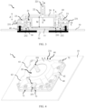
- a heat dissipation system 1 in this application includes a substrate 10, a jet cooling assembly 20, a sealing part 30, a rigid topplate 40, a rigid backplate 50, and a rigid position limiting structure 60.
- a heat generating device 11 is disposed on a side that is of the substrate 10 and that faces the jet cooling assembly 20, and the substrate 10 is, for example, a PCB board (Printed Circuit Board).
- An end part (an end part 232 described below) of the jet cooling assembly 20 is in contact with the heat generating device 11.
- the jet cooling assembly 20 has a coolant liquid inlet 221 and a jet hole, and the jet hole faces the heat generating device 11.
- the coolant liquid inlet 221 allows a coolant to flow in (where a dashed arrow B in FIG. 3 shows that the coolant flows in), and sprays the inflow coolant to a surface of the heat generating device 11 through the jet hole, to dissipate heat for the heat generating device 11.
- the coolant liquid inlet 221 of the jet cooling assembly 20 may be directly connected to a CDU (Coolant Distribution Unit, coolant distribution unit), and the CDU provides a coolant for the jet cooling assembly 20.
- CDU Coolant Distribution Unit, coolant distribution unit
- the sealing part 30 is located between the jet cooling assembly 20 and the heat generating device 11, and the sealing part 30 is configured to seal a part between the end part 232 of the jet cooling assembly 20 and the surface of the heat generating device 11.
- the sealing part 30, the jet cooling assembly 20, and the heat generating device 11 form a coolant outflow chamber 21, and the coolant outflow chamber 21 is configured to accommodate the coolant obtained after heat dissipation is performed on the heat generating device 11.
- the coolant outflow chamber 21 communicates with the jet hole of the jet cooling assembly 20.
- the heat generating device 11, the jet cooling assembly 20, and the sealing part 30 form the sealed coolant outflow chamber 21, and the coolant obtained after heat dissipation is performed on the heat generating device 11 flows out of the jet cooling assembly 20 through the coolant outflow chamber 21 (where a dashed arrow C in FIG. 3 shows that the coolant flows out).
- the rigid topplate 40 in this application is disposed on a side that is of the substrate 10.
- An example in which the heat generating device 11 is a chip is used for description.
- the chip is in a square shape
- the rigid topplate 40 has a square-shaped hollow-out structure
- the hollow-out structure of the rigid topplate 40 is disposed around peripheries of the chip.
- a shape of the chip is not limited thereto, and may be, for example, a circle or a rectangle.
- a shape of the hollow-out structure of the rigid topplate 40 adapts to the shape of the chip, to be disposed around the chip.
- the rigid topplate 40 is disposed opposite to the rigid backplate 50 on the other side of the substrate 10.
- the rigid topplate 40 and the rigid backplate 50 are located on two opposite sides of the substrate 10, and the rigid topplate 40 and the rigid backplate 50 jointly clamp the substrate 10. This is similar to a "sandwich" structure, and can enhance rigidity of the substrate 10.
- the rigid topplate 40 and the rigid backplate 50 of the rigid position limiting structure 60 are fastened to the substrate 10 through connectors 70 (where a specific structure of the connector 70 is described in detail below).
- the three components namely, the rigid position limiting structure 60, the rigid topplate 40, and the rigid backplate 50, are fastened through the connectors 70, there is height limiting space (as shown by M in FIG. 3 ) between the substrate 10 and the rigid position limiting structure 60 in the first direction, and at least a part of the jet cooling assembly 20 is located in the height limiting space.
- the coolant liquid inlet 221 of the jet cooling assembly 20 is located outside the height limiting space.
- the height limiting space limits movement of the jet cooling assembly 20 in a direction (as shown in a direction A in FIG. 3 and FIG. 4 ) away from the heat generating device 11, to keep the sealing part 30 in a sealed state.
- the height limiting space limits movement of the jet cooling assembly 20 in the direction (as shown in the direction A in FIG. 3 and FIG. 4 ) away from the heat generating device 11, to keep the sealing part 30 in the sealed state.
- the sealing part 30 is located between the jet cooling assembly 20 and the heat generating device 11, after the height limiting space effectively limits the movement of the jet cooling assembly 20 in the first direction, separation of the sealing part 30 and the jet cooling assembly 20 can be prevented, and the sealing part 30 is well compressed, so that the coolant outflow chamber 21 has good sealing effect.
- the height limiting space can also effectively limit the movement of the jet cooling assembly 20 in the first direction. Therefore, in this application, the sealing part 30 can well isolate the coolant in the coolant outflow chamber 21, prevent the coolant from flowing out of the substrate 10, and avoid a short circuit of a component and a line outside the substrate 10.
- the heat generating device 11 is a low-power consumption component (for example, a memory module, a PCIE card, a RAID card, or a hard disk) or a high-power consumption component (for example, a CPU, a GPU, or a chip).
- a manner of connecting the jet cooling assembly 20 to the CDU is not limited either.
- the jet cooling assembly 20 may be connected to the CDU through a quick connector, or the like, and the quick connector may support automatic liquid shutdown when the coupling is plugged or unplugged.
- a type of the sealing part 30 is not limited, and all sealing parts that can implement a sealing function fall within the protection scope of this application.
- the sealing part 30 is an O-shaped rubber ring.
- the rigid topplate 40, the rigid backplate 50, and the rigid position limiting structure 60 are made of rigid materials.
- a specific type of the rigid material is not limited, for example, is stainless steel or copper.
- the jet cooling assembly 20 is configured to spray the coolant to the surface of the heat generating device 11, to implement liquid cooling for the heat generating device 11.
- This liquid cooling manner for the heat generating device 11 is "jet impingement cooling".
- the jet impingement is a process in which a liquid or gas is jetted vertically (or at a specific angle) to a cooled surface through a circular or narrow-slit spray nozzle under a pressure difference, so that strong heat exchange effect is generated in an area directly impacted.
- a specific structure of the jet cooling assembly 20 is not limited in this application, and a structure form that can implement jet impingement cooling for the heat generating device 11 falls within the protection scope of this application. This application is described by using a structure of the jet cooling assembly 20 shown in FIG. 2 and FIG. 3 as an example.
- a body of the jet cooling assembly 20 is cylindrical.
- the jet cooling assembly 20 includes: one coolant inflow channel 22 and two coolant outflow channels 23, where the coolant inflow channel 22 has the liquid inlet 221, and the coolant outflow channels 23 has liquid outlets 231. That is, the jet cooling assembly 20 has one liquid inlet 221 and two liquid outlets 231.
- One end that is of the coolant inflow channel 22 and on which the liquid inlet 221 is disposed is protrudingly disposed on the body of the jet cooling assembly 20, and extends in the first direction (as shown in the Z direction in FIG. 2 and FIG. 3 ).
- Two ends that are of the coolant outflow channels 23 and on which liquid outlets 231 are disposed are also separately protrudingly disposed on the body of the jet cooling assembly 20, and extend in a direction perpendicular to the first direction (for example, a radial direction, as shown in an X direction in FIG. 2 ).
- a jet hole (not shown in the figure) disposed facing the heat generating device 11 is disposed on the coolant inflow channel 22, the coolant outflow channels 23 are disposed around the coolant inflow channel 22, and the end parts 232 of the coolant outflow channels 2 are in contact with the surface of the heat generating device 11.
- the coolant outflow channels 23 have open ends 233, and the open ends 233 of the coolant outflow channels 23 and the end parts 232 of the coolant outflow channels 23 are located on a same side of the jet cooling assembly 20.
- the end parts 232 of the coolant outflow channels 23 compress the sealing part 30, the sealing part 30 seals the open ends 233 of the coolant outflow channels 23 and the surface of the heat generating device 11, and the open ends 233 of the coolant outflow channels 23 are covered by the surface of the heat generating device 11, so that the coolant outflow channels 23, the sealing part 30, and the heat generating device 11 form the sealed coolant outflow chamber 21.
- the liquid inlet 221 of the coolant inflow channel 22 is, for example, connected to a CDU, the CDU provides the coolant for the liquid inlet 221, and the coolant flows into an internal channel chamber of the coolant inflow channel 22 from the liquid inlet 221.
- the internal channel chamber of the coolant inflow channel 22 is referred to as a jet chamber below.
- a high-speed jet is formed.
- the high-speed jet impacts a heat generating surface of the heat generating device 11, that is, the coolant in the jet chamber sprays the coolant to the surface of the heat generating device 11 through the jet hole, to implement liquid cooling for the heat generating surface of the heat generating device 11.
- the coolant obtained after heat dissipation for the heat generating device 11 flows into the coolant outflow channels 23, and then flows out from the liquid outlets 231 of the coolant outflow channels 23, for example, flows back to the CDU.
- the rigid position limiting structure 60 in this application includes the accommodating part 611 and the connecting part 62.
- the accommodating part 611 is configured to accommodate the body of the jet cooling assembly 20.
- the connecting part 62 extends outwards from an outer surface of the accommodating part 611, and the connecting part 62 is fastened to the substrate 10 with the rigid topplate 40 and the rigid backplate 50 through the connectors 70. After the connecting part 62, the rigid topplate 40, and the rigid backplate 50 are fastened, there is the height limiting space between the substrate 10 and the accommodating part 611.
- one end of the jet cooling assembly 20 is in contact with the heat generating device 11, and the other end is in contact with a top wall of the accommodating part 611.
- the height limiting space limits the movement of the jet cooling assembly 20 in the direction away from the heat generating device 11, to keep the sealing part 30 in the sealed state.
- a specific structure of the rigid position limiting structure 60 is not limited, and a structure that can accommodate the jet cooling assembly 20 falls within the protection scope of this application. Refer to FIG. 2 and FIG. 4 .
- the rigid position limiting structure 60 further includes the sleeve 61.
- An inner chamber of the sleeve 61 serves as the accommodating part 611, the inner chamber of the sleeve 61 adapts to a shape of the jet cooling assembly 20, and the inner chamber of the sleeve 61 accommodates the body of the jet cooling assembly 20.
- the body of the jet cooling assembly 20 is cylindrical, and correspondingly, the inner chamber of the sleeve 61 is also cylindrical.
- two ends of the sleeve 61 in the first direction have openings, and an opening at one end, back to the substrate 10, of the sleeve 61 in the first direction has a blocking part 6111.
- An outer circumferential surface of the sleeve 61 is provided with the vias 612 (refer to FIG. 4 ) for the two coolant outflow channels 23 of the jet cooling assembly 20 to extend out.
- the coolant inflow channel 22 of the jet cooling assembly 20 extends from the opening at one end, back to the substrate 10, of the sleeve 61 in the first direction, and abuts against the blocking part 6111 on the sleeve 61 in the first direction, and the two coolant outflow channels 23 of the jet cooling assembly 20 extend from the two vias 612 on the outer circumferential surface of the sleeve 61.
- the connecting part 62 is a flange, and the flange is formed by an end part of the sleeve 61 facing the substrate 10 extending outwards in the radial direction (as shown in the X direction in FIG. 2 ).
- the radial direction is perpendicular to the first direction.
- the flange is in contact with the rigid topplate 40, and a shape of the flange adapts to the rigid topplate 40.
- the rigid topplate 40 is in a square shape, and correspondingly, the flange is in a square shape.
- the rigid position limiting structure 60 further includes a plurality of ribs 63, and two ends of each rib 63 are respectively connected to the flange and the sleeve 61. Disposing of the ribs 63 may improve strength of the rigid position limiting structure 60.
- a quantity of the ribs 63 is not limited in this application.
- FIG. 2 and FIG. 4 show four ribs 63 distributed at four corners of the rigid position limiting structure 60. In some possible implementations, another quantity of, for example, 5 or 6, ribs 63 may be disposed based on an actual requirement.
- the following describes in detail a specific structure of the connector 70 in the heat dissipation system 1 with reference to the accompanying drawings.
- the specific structure of the connector 70 is not limited in this application, and a structure in which the rigid position limiting structure 60, the rigid topplate 40, and the rigid backplate 50 can be fastened falls within the protection scope of this application.
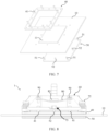
- the connector 70 includes a plurality of topplate screws 41 and a plurality of nut groups 71.
- the plurality of topplate screws 41 are disposed on a side that is of the rigid topplate 40 and that is opposite to the substrate 10, and topplate screw vias 621 one-to-one corresponding to the topplate screws 41 are disposed on the connecting part 62, where each of the topplate screws 41 is configured to pass through the topplate screw via 621 on the connecting part 62.
- the plurality of nut groups 71 one-to-one correspond to the plurality of topplate screws 41.
- Each of the nut groups 71 includes two washers 711 and two nuts 712.
- Each of the nut groups 71 clamps upper and lower sides of the connecting part 62 in the first direction through one topplate screw 41.
- the two washers 711 are respectively attached to the upper and lower sides of the connecting part 62 (as shown in FIG. 6 ).
- one washer 711 and one nut 712 are located on the upper side of the connecting part 62, and the other washer 711 and the other nut 712 are located on the lower side of the connecting part 62.
- the connecting part 62 of the rigid position limiting structure 60 When the connecting part 62 of the rigid position limiting structure 60 is connected to the rigid topplate 40, one nut 712 and one washer 711 are first sleeved on the topplate screw 41 in sequence, and then the topplate screw 41 passes through the topplate screw via 621 on the connecting part 62.
- the rigid position limiting structure 60 is in contact with the rigid topplate 40 in the first direction, and leaves space for accommodating the washer 711 and the nut 712. Then, the other washer 711 and the other nut 712 are sleeved on a part that is of the topplate screw 41 and that extends out of the connecting part 62 in sequence.
- the nuts 712 on the upper and lower sides of the connecting part 62 are separately tightened, so that the two washers 711 are respectively attached to the upper and lower sides of the connecting part 62.
- the rigid position limiting structure 60 and the rigid topplate 40 are fastened through the two nuts.
- the heat dissipation system 1 effectively limits movement of the jet cooling assembly 20 in the first direction, and prevents the sealing part 30 from being separated from the jet cooling assembly 20; and the sealing part 30 is well compressed, so that the coolant outflow chamber 21 has good sealing effect.
- the nut 712 in the nut group 71 is a hexagonal nut.
- the nut 712 in the nut group 71 may alternatively be another type of nut.
- a quantity and installation locations of the nut groups 71 are not limited in this application.
- the connector 70 in this application includes eight nut groups 71, and the eight nut groups 71 are distributed on the heat dissipation system 1 in an annular manner.
- FIG. 7 shows that eight topplate screws 41 are disposed on the rigid topplate 40, and two topplate screws 41 are disposed on each side of peripheries of the rigid topplate 40, and are located between two ribs 63.
- eight topplate screw vias 621 are disposed on the connecting part 62.
- a quantity of nut groups 71 may be six, ten, or the like.
- the nut groups 71 may alternatively be disposed at other locations of the heat dissipation system 1.
- the following describes a structure of the connector 70 between the three components: the rigid backplate 50, the rigid topplate 40, and the rigid position limiting structure 60.
- the connector 70 further includes a plurality of groups of spring screws 72, and each group of the spring screws 72 is located on the upper side of the connecting part 62, and fastens the connecting part 62, the rigid topplate 40, the substrate 10, and the rigid backplate 50 in sequence.
- a plurality of backplate screws 51 are disposed on a side that is of the rigid backplate 50 and that faces the substrate 10, the plurality of backplate screws 51 one-to-one correspond to the plurality of groups of spring screws 72, and backplate screw vias 622 one-to-one corresponding to the backplate screws 51 are disposed on the connecting part 62, the substrate 10, and the rigid topplate 40.
- Each of the backplate screws 51 has an inner thread, and the backplate screw 51 is configured to pass through the substrate 10, the rigid topplate 40, and the connecting part 62 in sequence, so that the spring screw 72 is in a thread connection with the inner thread of the corresponding backplate screw 51.
- the three components: the rigid backplate 50, the rigid topplate 40, and the rigid position limiting structure 60, are connected through the connectors 70.
- the connecting part 62 of the rigid position limiting structure 60, the rigid topplate 40, and the rigid backplate 50 are fastened to the substrate 10 through the spring screws 72. That the spring screws 72 serve as the connectors 70 can control installation force between the connecting part 62, the rigid topplate 40, and the rigid backplate 50, to prevent the heat generating device 11 from being damaged due to excessive force.
- the connecting part 62 of the rigid position limiting structure 60 Before the connecting part 62 of the rigid position limiting structure 60 is fastened to the rigid topplate 40 through the nut groups 71, the connecting part 62 of the rigid position limiting structure 60, the rigid topplate 40, and the rigid backplate 50 are first connected through the spring screws 72 with preset installation force, and then the connecting part 62 of the rigid position limiting structure 60 is fastened to the rigid topplate 40 through the nut groups 71.
- Spring force provided by the spring screws 72 is designed to be only equal to rebound force obtained after the sealing part 30 is compressed, and the spring force is small, for example, 30 kg to 50 kg.
- the rigid position limiting structure 60 can ensure that the spring force is evenly applied to the sealing part 30.
- Such spring force has small pressure on a contact surface of the heat generating device 11, for example, 0.1 Mpa to 0.4 Mpa, to ensure that the heat generating device 11 is not damaged.
- the rigid position limiting structure 60, the rigid topplate 40, and the rigid backplate 50 are fastened through the spring screws 72 and the backplate screws 51.
- the backplate screw 51 may not be disposed, inner thread holes are disposed on the connecting part 62, the rigid topplate 40, the substrate 10, and the rigid backplate 50 separately, and the spring screws 72 is in a thread connection with the inner thread holes on the connecting part 62, the rigid topplate 40, the substrate 10, and the rigid backplate 50 in sequence.
- the rigid position limiting structure 60, the rigid topplate 40, and the rigid backplate 50 can also be fastened.
- FIG. 4 shows four spring screws 72 that are respectively located at four corners of the connecting part 62 (connection points between the ribs 63 and the connecting part 62).
- four backplate screw holes 51 are disposed at the corresponding locations on the rigid backplate 50
- four backplate screw holes 622 are respectively disposed at four corners on the connecting part 62, the substrate 10, and the rigid topplate 40.
- a quantity of spring screws 72 may be six, eight, or the like.
- the spring screws 72 may alternatively be disposed at other locations of the heat dissipation system 1.
- the connector 70 further includes a plurality of additional backplate screws 52 and a plurality of upper nuts 73.
- the plurality of additional backplate screws 52 are disposed on a side that is of the rigid backplate 50 and that faces the substrate 10, additional backplate screw vias one-to-one corresponding to the additional backplate screws 52 are disposed on the connecting part 62, the substrate 10, and the rigid topplate 40, and the additional backplate screws 52 are configured to pass through the substrate 10, the rigid topplate 40, and the connecting part 62 in sequence.
- the plurality of upper nuts 73 one-to-one correspond to the additional backplate screws 52.
- Each of the upper nuts 73 is located on the upper side of the connecting part 62 of the rigid position limiting structure 60.
- the upper nut 73 is in a thread connection with a part that is of the additional backplate screw 52 and that extends out of the connecting part 62 of the rigid position limiting structure 60, so that the rigid backplate 50, the rigid topplate 40, and the connecting part 62 are fastened.
- the rigid backplate 50, the rigid topplate 40, and the rigid position limiting structure 60 are fastened in a "single nut" form, and the rigid position limiting structure 60, the rigid topplate 40, and the rigid backplate 50 can also be fastened to each other.
- the upper nut 73 is a hexagonal nut. In another implementation, the upper nut 73 may be a nut of another type.
- the connecting part 62 of the rigid position limiting structure 60 and the rigid topplate 40 are fastened through the nut groups 71, and the rigid position limiting structure 60, the rigid topplate 40, and the rigid backplate 50 are fastened to each other through the additional backplate screws 52, the upper nuts 73, and the spring screws 72. Therefore, in some possible implementations, after the connecting part 62 of the rigid position limiting structure 60 and the rigid topplate 40 are fastened through the nut groups 71, the spring screws 72 may be removed.
- the rigid position limiting structure 60, the rigid topplate 40, and the rigid backplate 50 are connected through the spring screws 72, and after the installation force is controlled, the rigid position limiting structure 60, the rigid topplate 40, and the rigid backplate 50 are fastened through the additional backplate screws 52 and the upper nuts 73, and the connecting part 62 of the rigid position limiting structure 60 and the rigid topplate 40 are fastened through the nut groups 71. Therefore, after the spring screws 72 are removed, connection stability between the rigid position limiting structure 60, the rigid topplate 40, and the rigid backplate 50 is slightly affected.
- the rigid backplate 50, the rigid topplate 40, and the rigid position limiting structure 60 are fastened only in the "single nut" form.
- the rigid position limiting structure 60 and the rigid topplate 40 are fastened through two nuts.
- this application is not limited thereto.
- the rigid backplate 50, the rigid topplate 40, and the rigid position limiting structure 60 are fastened in the "single nut" form, and the rigid topplate 40 and the rigid position limiting structure 60 are fastened without using the nut groups 71.
- the connector 70 includes a plurality of topplate screws 41 and a plurality of fastening springs 80.
- the plurality of topplate screws 41 are disposed on the rigid topplate 40, every two topplate screws 41 are located on a same side of peripheries the rigid topplate 40, topplate screw vias 621 one-to-one corresponding to the topplate screws 41 are disposed on the connecting part 62, the topplate screws 41 are configured to pass through the topplate screw vias 621 on the connecting part 62, and each of the topplate screws 41 has an inner thread.
- the connecting part 62 of the rigid position limiting structure 60 When the connecting part 62 of the rigid position limiting structure 60 is connected to the rigid topplate 40, the topplate screw 41 passes through the topplate screw via 621 on the connecting part 62, and the locking screws 90 are separately inserted into the locking holes 81 at two ends of the fastening springs 80.
- the locking screw 90 at each end of the fastening spring 80 is in a thread connection with the inner thread of the corresponding topplate screw 41. In this way, the connecting part 62 of the rigid position limiting structure 60 is connected to the rigid topplate 40. Because the fastening springs 80 are connected to two topplate screws 41 at the same time, a connection point between the rigid topplate 40 and the connecting part 62 of the rigid position limiting structure 60 can be prevented from loosening.
- a quantity and installation locations of fastening springs 80 are not limited in this application.
- the connector 70 in this application includes four fastening springs 80 that are respectively located between two ribs 63.
- a quantity of the fastening springs 80 may be one, two, six, or the like.
- the fastening springs 80 may alternatively be disposed at other locations of the rigid topplate 40.
- the fastening springs 80 may correspond to two topplate screws 41 on different sides.
- the upper nut 73 is a hexagonal nut
- the nut slot 83 is a hexagonal nut slot
- the hexagonal nut is limited in the hexagonal nut slot.
- the extending part of the jet cooling assembly 20 is fastened to the rigid topplate 40 and the rigid backplate 50 through connectors, and can also limit movement of the jet cooling assembly 20 in the first direction.
- the structure of the connector 70 described in the foregoing embodiment may be used as the structure of the connector between the extending part of the jet cooling assembly 20 and the rigid topplate 40 and the rigid backplate 50. That is, refer to a specific form in which the connecting part 62, the rigid backplate 50, and the rigid topplate 40 are connected through the connectors 70 in the foregoing embodiment, for example, the connection form of "nut group", "single nut", or "spring screw".
- This application further provides an electronic device, including the heat dissipation system 1 and the heat generating device 11 according to any one of the foregoing embodiments.
- the heat dissipation system 1 is configured to dissipate heat of the heat generating device 11 in the electronic device.
- the electronic device is, for example, a server like a blade server or a rack server.
- the jet cooling assembly 20 of the heat dissipation system 1 performs jet impingement cooling on the heat generating device 11 in the server.
- the cooling apparatus is a CDU.
- the CDU is an industrial component that has a power function of temperature control, includes a plate heat exchanger (not shown in the figure), and can implement heat exchange on a primary side and a secondary side.
- the primary side is usually a cooling distribution unit, and a cold working medium provided by the cooling distribution unit flows under driving of a cooling pump.
- the secondary side is the electronic device in embodiments of this application. That is, the CDU implements heat exchange between the cold working medium in the cooling distribution unit and the coolant in the electronic device.
- the cooling distribution unit is a heat exchange device in an environment, and is usually a cooling tower.
- a type of the cooling distribution unit is not limited in this application, and may be another apparatus that can provide a cold working medium.
Landscapes
- Physics & Mathematics (AREA)
- Thermal Sciences (AREA)
- Engineering & Computer Science (AREA)
- Microelectronics & Electronic Packaging (AREA)
- Cooling Or The Like Of Electrical Apparatus (AREA)
Applications Claiming Priority (1)
| Application Number | Priority Date | Filing Date | Title |
|---|---|---|---|
| PCT/CN2021/126533 WO2023070342A1 (fr) | 2021-10-27 | 2021-10-27 | Système de dissipation de chaleur, dispositif électronique et système de refroidissement de liquide |
Publications (2)
| Publication Number | Publication Date |
|---|---|
| EP4386833A1 true EP4386833A1 (fr) | 2024-06-19 |
| EP4386833A4 EP4386833A4 (fr) | 2024-11-13 |
Family
ID=86160278
Family Applications (1)
| Application Number | Title | Priority Date | Filing Date |
|---|---|---|---|
| EP21961718.0A Pending EP4386833A4 (fr) | 2021-10-27 | 2021-10-27 | Système de dissipation de chaleur, dispositif électronique et système de refroidissement de liquide |
Country Status (3)
| Country | Link |
|---|---|
| EP (1) | EP4386833A4 (fr) |
| CN (1) | CN117616556A (fr) |
| WO (1) | WO2023070342A1 (fr) |
Families Citing this family (2)
| Publication number | Priority date | Publication date | Assignee | Title |
|---|---|---|---|---|
| CN116806089A (zh) * | 2023-05-31 | 2023-09-26 | 华能国际电力江苏能源开发有限公司 | 一种流量积算装置的散热机构 |
| CN119852265B (zh) * | 2025-03-18 | 2025-06-10 | 成都贡爵微电子有限公司 | 一种射频微系统三维互连的散热结构 |
Family Cites Families (12)
| Publication number | Priority date | Publication date | Assignee | Title |
|---|---|---|---|---|
| US7079393B2 (en) * | 2004-11-16 | 2006-07-18 | International Business Machines Corporation | Fluidic cooling systems and methods for electronic components |
| US9247672B2 (en) * | 2013-01-21 | 2016-01-26 | Parker-Hannifin Corporation | Passively controlled smart microjet cooling array |
| CN105208837A (zh) * | 2015-10-29 | 2015-12-30 | 中国电子科技集团公司第二十研究所 | 基于封闭微喷射流的错列微细通道热沉装置 |
| US10468331B2 (en) * | 2018-01-12 | 2019-11-05 | Intel Corporation | Heat management system |
| CN109524376B (zh) * | 2018-09-18 | 2020-07-10 | 华中科技大学 | 一种多歧式射流微通道芯片液冷散热装置 |
| CN209029558U (zh) * | 2018-10-15 | 2019-06-25 | 富顶精密组件(深圳)有限公司 | 电连接器组件及其液氮散热器 |
| US20210280497A1 (en) * | 2020-03-05 | 2021-09-09 | Intel Corporation | Modular technique for die-level liquid cooling |
| CN111446221B (zh) * | 2020-05-08 | 2022-03-08 | 西安交通大学 | 一种低流阻芯片嵌入式阵列微射流散热器及其制造方法 |
| US11310937B2 (en) * | 2020-05-29 | 2022-04-19 | Google Llc | Impinging jet manifold for chip cooling near edge jets |
| CN112099592B (zh) * | 2020-07-21 | 2022-06-21 | 曙光数据基础设施创新技术(北京)股份有限公司 | 刀片服务器壳内部的自循环浸没射流相变液冷散热装置 |
| CN111900143A (zh) * | 2020-07-31 | 2020-11-06 | 上海交通大学 | 一种歧管式高深宽比微通道换热器 |
| CN111949091A (zh) * | 2020-09-27 | 2020-11-17 | 北京一莱汀光电技术发展有限公司 | 一种密封喷淋散热式计算机机箱 |
-
2021
- 2021-10-27 EP EP21961718.0A patent/EP4386833A4/fr active Pending
- 2021-10-27 CN CN202180100317.0A patent/CN117616556A/zh active Pending
- 2021-10-27 WO PCT/CN2021/126533 patent/WO2023070342A1/fr not_active Ceased
Also Published As
| Publication number | Publication date |
|---|---|
| WO2023070342A1 (fr) | 2023-05-04 |
| CN117616556A (zh) | 2024-02-27 |
| EP4386833A4 (fr) | 2024-11-13 |
Similar Documents
| Publication | Publication Date | Title |
|---|---|---|
| EP4386833A1 (fr) | Système de dissipation de chaleur, dispositif électronique et système de refroidissement de liquide | |
| US5465192A (en) | Cooling apparatus for integrated circuit chips for preventing forcible contact between a cooling member and the chips | |
| US7486514B2 (en) | Cooling apparatus with discrete cold plates disposed between a module enclosure and electronics components to be cooled | |
| AU701552B2 (en) | Apparatus and method for spray-cooling an electronic module | |
| EP4062722B1 (fr) | Agencement de buse et module de refroidissement | |
| US5046552A (en) | Flow-through heat transfer apparatus with movable thermal via | |
| AU1062497A (en) | Apparatus for spray-cooling multiple electronic modules | |
| US5761035A (en) | Circuit board apparatus and method for spray-cooling a circuit board | |
| US11800682B2 (en) | Cooling module and a method of assembling the cooling module to an electronic circuit module | |
| US20220071059A1 (en) | Heat dissipation system and server system | |
| WO2022222870A1 (fr) | Appareil de refroidissement par jet, ensemble puce et dispositif électronique | |
| CN114945263A (zh) | 一种高效散热静音密闭液冷机柜 | |
| CN114501945A (zh) | 一种服务器用喷雾液冷相变模组、控制方法及其制造方法 | |
| US20030218865A1 (en) | Semiconductor thermal management system | |
| WO1999006782A1 (fr) | Appareil et procede de refroidissement d'un composant electronique au moyen d'un materiau poreux | |
| US20260052988A1 (en) | Chip package structure and electronic device | |
| CN213934803U (zh) | 液冷装置 | |
| US7661276B1 (en) | Evaporator | |
| CN216770255U (zh) | 一种点波填料横流式冷却塔 | |
| CN222381736U (zh) | 监控装置外壳用防护设备 | |
| CN223985617U (zh) | 一种铜复合材料制成的散热盘管装置 | |
| CN223362920U (zh) | 一种电力变压器的散热结构 | |
| CN219531753U (zh) | 一种衔接机构及冷却器 | |
| CN222836471U (zh) | 一种法兰盘的定位连接结构 | |
| CN220733282U (zh) | 一种挂片装置及液冷系统 |
Legal Events
| Date | Code | Title | Description |
|---|---|---|---|
| STAA | Information on the status of an ep patent application or granted ep patent |
Free format text: STATUS: THE INTERNATIONAL PUBLICATION HAS BEEN MADE |
|
| PUAI | Public reference made under article 153(3) epc to a published international application that has entered the european phase |
Free format text: ORIGINAL CODE: 0009012 |
|
| STAA | Information on the status of an ep patent application or granted ep patent |
Free format text: STATUS: REQUEST FOR EXAMINATION WAS MADE |
|
| 17P | Request for examination filed |
Effective date: 20240312 |
|
| AK | Designated contracting states |
Kind code of ref document: A1 Designated state(s): AL AT BE BG CH CY CZ DE DK EE ES FI FR GB GR HR HU IE IS IT LI LT LU LV MC MK MT NL NO PL PT RO RS SE SI SK SM TR |
|
| A4 | Supplementary search report drawn up and despatched |
Effective date: 20241010 |
|
| RIC1 | Information provided on ipc code assigned before grant |
Ipc: H01L 23/40 20060101ALI20241004BHEP Ipc: H05K 7/20 20060101ALI20241004BHEP Ipc: H01L 23/473 20060101AFI20241004BHEP |
|
| DAV | Request for validation of the european patent (deleted) | ||
| DAX | Request for extension of the european patent (deleted) |