EP4386946A1 - Module de batterie et bloc-batterie le comprenant - Google Patents
Module de batterie et bloc-batterie le comprenant Download PDFInfo
- Publication number
- EP4386946A1 EP4386946A1 EP23214465.9A EP23214465A EP4386946A1 EP 4386946 A1 EP4386946 A1 EP 4386946A1 EP 23214465 A EP23214465 A EP 23214465A EP 4386946 A1 EP4386946 A1 EP 4386946A1
- Authority
- EP
- European Patent Office
- Prior art keywords
- battery
- support member
- battery module
- cell assemblies
- module
- Prior art date
- Legal status (The legal status is an assumption and is not a legal conclusion. Google has not performed a legal analysis and makes no representation as to the accuracy of the status listed.)
- Pending
Links
Images


Classifications
-
- H—ELECTRICITY
- H01—ELECTRIC ELEMENTS
- H01M—PROCESSES OR MEANS, e.g. BATTERIES, FOR THE DIRECT CONVERSION OF CHEMICAL ENERGY INTO ELECTRICAL ENERGY
- H01M50/00—Constructional details or processes of manufacture of the non-active parts of electrochemical cells other than fuel cells, e.g. hybrid cells
- H01M50/20—Mountings; Secondary casings or frames; Racks, modules or packs; Suspension devices; Shock absorbers; Transport or carrying devices; Holders
- H01M50/289—Mountings; Secondary casings or frames; Racks, modules or packs; Suspension devices; Shock absorbers; Transport or carrying devices; Holders characterised by spacing elements or positioning means within frames, racks or packs
- H01M50/291—Mountings; Secondary casings or frames; Racks, modules or packs; Suspension devices; Shock absorbers; Transport or carrying devices; Holders characterised by spacing elements or positioning means within frames, racks or packs characterised by their shape
-
- H—ELECTRICITY
- H01—ELECTRIC ELEMENTS
- H01M—PROCESSES OR MEANS, e.g. BATTERIES, FOR THE DIRECT CONVERSION OF CHEMICAL ENERGY INTO ELECTRICAL ENERGY
- H01M50/00—Constructional details or processes of manufacture of the non-active parts of electrochemical cells other than fuel cells, e.g. hybrid cells
- H01M50/10—Primary casings; Jackets or wrappings
- H01M50/102—Primary casings; Jackets or wrappings characterised by their shape or physical structure
- H01M50/103—Primary casings; Jackets or wrappings characterised by their shape or physical structure prismatic or rectangular
-
- H—ELECTRICITY
- H01—ELECTRIC ELEMENTS
- H01M—PROCESSES OR MEANS, e.g. BATTERIES, FOR THE DIRECT CONVERSION OF CHEMICAL ENERGY INTO ELECTRICAL ENERGY
- H01M50/00—Constructional details or processes of manufacture of the non-active parts of electrochemical cells other than fuel cells, e.g. hybrid cells
- H01M50/20—Mountings; Secondary casings or frames; Racks, modules or packs; Suspension devices; Shock absorbers; Transport or carrying devices; Holders
- H01M50/289—Mountings; Secondary casings or frames; Racks, modules or packs; Suspension devices; Shock absorbers; Transport or carrying devices; Holders characterised by spacing elements or positioning means within frames, racks or packs
-
- H—ELECTRICITY
- H01—ELECTRIC ELEMENTS
- H01M—PROCESSES OR MEANS, e.g. BATTERIES, FOR THE DIRECT CONVERSION OF CHEMICAL ENERGY INTO ELECTRICAL ENERGY
- H01M50/00—Constructional details or processes of manufacture of the non-active parts of electrochemical cells other than fuel cells, e.g. hybrid cells
- H01M50/20—Mountings; Secondary casings or frames; Racks, modules or packs; Suspension devices; Shock absorbers; Transport or carrying devices; Holders
- H01M50/202—Casings or frames around the primary casing of a single cell or a single battery
-
- H—ELECTRICITY
- H01—ELECTRIC ELEMENTS
- H01M—PROCESSES OR MEANS, e.g. BATTERIES, FOR THE DIRECT CONVERSION OF CHEMICAL ENERGY INTO ELECTRICAL ENERGY
- H01M50/00—Constructional details or processes of manufacture of the non-active parts of electrochemical cells other than fuel cells, e.g. hybrid cells
- H01M50/20—Mountings; Secondary casings or frames; Racks, modules or packs; Suspension devices; Shock absorbers; Transport or carrying devices; Holders
- H01M50/204—Racks, modules or packs for multiple batteries or multiple cells
- H01M50/207—Racks, modules or packs for multiple batteries or multiple cells characterised by their shape
- H01M50/209—Racks, modules or packs for multiple batteries or multiple cells characterised by their shape adapted for prismatic or rectangular cells
-
- H—ELECTRICITY
- H01—ELECTRIC ELEMENTS
- H01M—PROCESSES OR MEANS, e.g. BATTERIES, FOR THE DIRECT CONVERSION OF CHEMICAL ENERGY INTO ELECTRICAL ENERGY
- H01M50/00—Constructional details or processes of manufacture of the non-active parts of electrochemical cells other than fuel cells, e.g. hybrid cells
- H01M50/20—Mountings; Secondary casings or frames; Racks, modules or packs; Suspension devices; Shock absorbers; Transport or carrying devices; Holders
- H01M50/244—Secondary casings; Racks; Suspension devices; Carrying devices; Holders characterised by their mounting method
-
- H—ELECTRICITY
- H01—ELECTRIC ELEMENTS
- H01M—PROCESSES OR MEANS, e.g. BATTERIES, FOR THE DIRECT CONVERSION OF CHEMICAL ENERGY INTO ELECTRICAL ENERGY
- H01M50/00—Constructional details or processes of manufacture of the non-active parts of electrochemical cells other than fuel cells, e.g. hybrid cells
- H01M50/20—Mountings; Secondary casings or frames; Racks, modules or packs; Suspension devices; Shock absorbers; Transport or carrying devices; Holders
- H01M50/249—Mountings; Secondary casings or frames; Racks, modules or packs; Suspension devices; Shock absorbers; Transport or carrying devices; Holders specially adapted for aircraft or vehicles, e.g. cars or trains
-
- H—ELECTRICITY
- H01—ELECTRIC ELEMENTS
- H01M—PROCESSES OR MEANS, e.g. BATTERIES, FOR THE DIRECT CONVERSION OF CHEMICAL ENERGY INTO ELECTRICAL ENERGY
- H01M50/00—Constructional details or processes of manufacture of the non-active parts of electrochemical cells other than fuel cells, e.g. hybrid cells
- H01M50/20—Mountings; Secondary casings or frames; Racks, modules or packs; Suspension devices; Shock absorbers; Transport or carrying devices; Holders
- H01M50/258—Modular batteries; Casings provided with means for assembling
-
- H—ELECTRICITY
- H01—ELECTRIC ELEMENTS
- H01M—PROCESSES OR MEANS, e.g. BATTERIES, FOR THE DIRECT CONVERSION OF CHEMICAL ENERGY INTO ELECTRICAL ENERGY
- H01M50/00—Constructional details or processes of manufacture of the non-active parts of electrochemical cells other than fuel cells, e.g. hybrid cells
- H01M50/20—Mountings; Secondary casings or frames; Racks, modules or packs; Suspension devices; Shock absorbers; Transport or carrying devices; Holders
- H01M50/262—Mountings; Secondary casings or frames; Racks, modules or packs; Suspension devices; Shock absorbers; Transport or carrying devices; Holders with fastening means, e.g. locks
-
- H—ELECTRICITY
- H01—ELECTRIC ELEMENTS
- H01M—PROCESSES OR MEANS, e.g. BATTERIES, FOR THE DIRECT CONVERSION OF CHEMICAL ENERGY INTO ELECTRICAL ENERGY
- H01M50/00—Constructional details or processes of manufacture of the non-active parts of electrochemical cells other than fuel cells, e.g. hybrid cells
- H01M50/20—Mountings; Secondary casings or frames; Racks, modules or packs; Suspension devices; Shock absorbers; Transport or carrying devices; Holders
- H01M50/271—Lids or covers for the racks or secondary casings
-
- H—ELECTRICITY
- H01—ELECTRIC ELEMENTS
- H01M—PROCESSES OR MEANS, e.g. BATTERIES, FOR THE DIRECT CONVERSION OF CHEMICAL ENERGY INTO ELECTRICAL ENERGY
- H01M50/00—Constructional details or processes of manufacture of the non-active parts of electrochemical cells other than fuel cells, e.g. hybrid cells
- H01M50/50—Current conducting connections for cells or batteries
- H01M50/502—Interconnectors for connecting terminals of adjacent batteries; Interconnectors for connecting cells outside a battery casing
- H01M50/505—Interconnectors for connecting terminals of adjacent batteries; Interconnectors for connecting cells outside a battery casing comprising a single busbar
-
- H—ELECTRICITY
- H01—ELECTRIC ELEMENTS
- H01M—PROCESSES OR MEANS, e.g. BATTERIES, FOR THE DIRECT CONVERSION OF CHEMICAL ENERGY INTO ELECTRICAL ENERGY
- H01M2220/00—Batteries for particular applications
- H01M2220/20—Batteries in motive systems, e.g. vehicle, ship, plane
-
- H—ELECTRICITY
- H01—ELECTRIC ELEMENTS
- H01M—PROCESSES OR MEANS, e.g. BATTERIES, FOR THE DIRECT CONVERSION OF CHEMICAL ENERGY INTO ELECTRICAL ENERGY
- H01M2220/00—Batteries for particular applications
- H01M2220/30—Batteries in portable systems, e.g. mobile phone, laptop
-
- Y—GENERAL TAGGING OF NEW TECHNOLOGICAL DEVELOPMENTS; GENERAL TAGGING OF CROSS-SECTIONAL TECHNOLOGIES SPANNING OVER SEVERAL SECTIONS OF THE IPC; TECHNICAL SUBJECTS COVERED BY FORMER USPC CROSS-REFERENCE ART COLLECTIONS [XRACs] AND DIGESTS
- Y02—TECHNOLOGIES OR APPLICATIONS FOR MITIGATION OR ADAPTATION AGAINST CLIMATE CHANGE
- Y02E—REDUCTION OF GREENHOUSE GAS [GHG] EMISSIONS, RELATED TO ENERGY GENERATION, TRANSMISSION OR DISTRIBUTION
- Y02E60/00—Enabling technologies; Technologies with a potential or indirect contribution to GHG emissions mitigation
- Y02E60/10—Energy storage using batteries
Definitions
- the present disclosure relates to a battery module and a battery pack including the same.
- secondary batteries battery cells
- battery cells are convenient, in that they may be charged and discharged and have come to prominence as a power source for various mobile devices and electric vehicles.
- Battery modules are obtained by modularizing a plurality of battery cells by electrically connecting the battery cells due to the need for high power and high capacity, and a battery pack including a plurality of battery modules may be applied to devices requiring high power, such as electric vehicles.
- Such a high-capacity battery pack may include multiple frame structures inside a case (or a housing) for structural rigidity.
- dead space may be formed between the battery module and the aforementioned frame structure due to manufacturing tolerance. As a power value required for the battery pack increases, more battery modules are arranged, and as a result, dead space may increase, eventually leading to a decrease in energy density of the battery pack.
- An aspect of the present disclosure is to provide a battery pack capable of maintaining structural rigidity, while having high energy density.
- An aspect of the present disclosure is to provide a battery module and a battery pack having high structural stability by disposing a support member between a plurality of battery cells.
- An aspect of the present disclosure is to provide a structure in which a large battery module may be disposed in a limited space inside a battery pack.
- a battery module includes: a plurality of cell assemblies respectively including a plurality of battery cells stacked in a first direction; a support member disposed between the plurality of cell assemblies; and a plurality of end covers facing at least one of the plurality of cell assemblies in the first direction, wherein the support member protrudes in the first direction, relative to the plurality of end covers.
- the battery module may further include: a module housing in which the plurality of cell assemblies and the support member are accommodated, wherein the module housing includes: a top cover covering the top of the plurality of cell assemblies; and a side cover connected to the top cover and facing the plurality of cell assemblies in a second direction, perpendicular to the first direction.
- At least one of the plurality of battery cells may include: a case in which an electrode assembly is accommodated; and a cap assembly coupled to the case, in which electrode terminals are arranged.
- the cap assembly may face the top cover.
- a bottom surface of the case may be exposed to the outside of the module housing.
- the support member may include: a body portion facing at least one of the plurality of cell assemblies in a second direction, perpendicular to the first direction; and an extension portion extending from the body portion in the first direction and passing between the plurality of end covers.
- the extension portion may be disposed on each of both end portions of the support member in the first direction.
- the extension portion and the plurality of end covers may be alternately arranged in the second direction.
- the plurality of end covers may be welded to the extension portion.
- a battery pack includes: a plurality of battery modules; and a pack housing in which the plurality of battery modules are accommodated, wherein at least one of the plurality of battery modules includes: a plurality of cell assemblies respectively including a plurality of battery cells stacked in a first direction; a support member disposed between the plurality of cell assemblies; and a plurality of end covers facing at least one of the plurality of cell assemblies in the first direction, wherein the support member protrudes in the first direction, relative to the plurality of end covers and is coupled to the pack housing.
- the support member may include: a body portion facing at least one of the plurality of cell assemblies in a second direction, perpendicular to the first direction; and an extension portion extending from the body portion in the first direction and passing between the plurality of end covers.
- the pack housing may include: a bottom frame facing bottom surfaces of the plurality of battery modules; and a plurality of side frames connected to the bottom frame and facing the plurality of battery modules in the first direction, wherein the extension portion is coupled to the plurality of side frames.
- a length of the support member in the first direction may be equal to or greater than a gap between the plurality of side frames.
- the extension portion may include an insertion protrusion
- the plurality of side frames may include an insertion groove into which the insertion protrusion is inserted.
- the battery pack may further include: a fastening member fastened to the insertion groove through the insertion protrusion.
- a battery pack capable of maintaining structural rigidity, while having high energy density, may be implemented.
- a battery module and a battery pack having high structural stability may be provided by disposing the support member between a plurality of battery cells.
- a large battery module may be disposed within a limited space inside a battery pack.
- ordinal numbers such as 'first', 'second', etc. May be used herein to distinguish elements from one another. These ordinal numbers are merely used to distinguish the same or similar elements from one another, and meanings of the terms are not construed as being limited by the using of the ordinal numbers. For example, use orders or arrangement orders of elements combined with these ordinal numbers are not limited by numbers thereof. The ordinal numbers may be redisposed with one another.
- FIG. 1 is a perspective view of a battery module 10.
- FIG. 2 is an exploded perspective view of the battery module 10.
- FIG. 3 is an exploded perspective view of a battery cell 1000 included in the battery module 10.
- FIG. 4 illustrates a configuration in which an end cover 400 is coupled a module housing 300 and a support member 200.
- FIG. 5 is a top view of the battery module 10.
- the battery module 10 may include a plurality of cell assemblies 100, a support member 200 disposed between the cell assemblies 100, and a module housing 300 providing an internal space in which the cell assemblies 100 are accommodated.
- a plurality of cell assemblies 100 may be arranged inside the module housing 300.
- Each cell assembly 100 may include a plurality of battery cells 1000 and may be configured to store or emit electrical energy.
- the cell assembly 100 may include a plurality of battery cells 1000 stacked in one direction, a busbar (not shown) electrically connecting the plurality of battery cells 1000, and a cell protection member (not shown) disposed between the plurality of battery cells 1000 to protect the battery cells 1000.
- the battery cells 1000 of the cell assembly 100 may be stacked and arranged in one direction (for example, an X-axis direction) and may be electrically connected to each other to store or output electrical energy.
- a stacking direction of the battery cells 1000 included in the cell assembly 100 is referred to as a 'first direction' or a 'cell stacking direction.'
- the cell assembly 100 may include a plurality of busbars (not shown) electrically connecting the battery cells 1000.
- the busbar (not shown) may be electrically connected to a terminal portion 1310 of each battery cell 1000.
- the cell assembly 100 may further include a cell protection member (not shown) to protect the battery cell 1000.
- the cell protection member (not shown) may be disposed between the plurality of battery cells 1000.
- the cell protection member (not shown) may be an insulating member (not shown) or a compression member (not shown).
- the insulating member may block flames or high-temperature heat energy from propagating between neighboring battery cells 1000, thereby preventing a chain ignition phenomenon from occurring inside the cell assembly 100.
- the insulating member may include at least one of mica, silica, silicate, graphite, alumina, ceramic wool, or aerogel, which may perform the function of preventing the spread of heat and/or flames.
- the compression member may be compressed and elastically deformed when a specific battery cell 1000 expands, thereby suppressing expansion of the overall volume of the cell assembly 100.
- the compression member may be formed of polyurethane foam and may have a size corresponding to a large surface of the battery cell 1000.
- An adhesive member (not shown) capable of fixing the battery cells 1000 to each other may be disposed between the battery cells 1000.
- the adhesive member (not shown) may be configured as a binder or adhesive tape.
- the plurality of battery cells 1000 may be stacked in the first direction (the X-axis direction) and fixed to each other by an adhesive member (not shown).
- a plurality of cell assemblies 100 may be electrically connected to each other and configured to output a design power value required for the battery module 10.
- two cell assemblies 100 facing each other with the support member 200 therebetween may be connected to each other in series or parallel.
- the plurality of cell assemblies 100 may be configured to be electrically separated from each other.
- two cell assemblies 100 facing each other with a support member 200 therebetween may be electrically separated from each other, and each cell assembly 100 may be configured to be electrically connected to another neighboring battery module 10.
- the battery cell 1000 included in the cell assembly 100 may be a secondary battery.
- the battery cell 1000 may be formed of a lithium secondary battery, but is not limited thereto.
- the battery cell 1000 may be a prismatic secondary battery in which an electrode assembly is stored inside a rigid case 1200.
- the battery cell 1000 may include an electrode assembly 1100, a case 1200, and a cap assembly 1300.
- the electrode assembly 1100 may be received in the case 1200 together with an electrolyte.
- the electrode assembly 1100 may include an uncoated portion 1110 on which no active material is applied.
- the uncoated portion 1110 may be electrically connected to the terminal portion 1310 of the cap assembly 1300.
- the case 1200 may be formed of a conductive metal, such as aluminum, aluminum alloy, or nickel-plated steel.
- the case 1200 may have a hexahedral shape that is open in at least one direction so that the electrode assembly 110 may be inserted and seated.
- An inner surface of the case 1200 may be insulated to be insulated from the electrode assembly 1100.
- the cap assembly 1300 may seal the top opening of the case 1200 and close an internal space of the case 1200. At least a portion of the cap assembly 1300 may be formed of the same material as that of the case 1200 and may be welded and coupled to the case 1200.
- the cap assembly 1300 may include the terminal portion 1310 electrically connected to the uncoated portion 1110 of the electrode assembly 1100.
- the terminal portion 1310 may be formed of metal.
- the type of battery cell included in the battery module 10 is not limited to the prismatic secondary battery described above.
- the battery cell may be a pouch-type secondary battery having a structure in which an electrode assembly is stored inside a flexible pouch.
- the module housing 300 may include a top cover 310 covering the top of the plurality of cell assemblies 100 and a side cover 320 connected to the top cover 310.
- the top cover 310 formed integrally, may be disposed to cover top surfaces of the plurality of cell assemblies 100.
- the side cover 320 may be connected to the top cover 310 to cover the side of the cell assembly.
- top cover 310 and the side covers 320 are not limited to those shown in FIG. 2 .
- a plurality of top covers 310 of the module housing 300 may be provided, and in this case, each top cover 310 may be disposed to cover a different cell assembly 100.
- the module housing 300 may have a shape that is open in a downward direction (e.g., in a negative Z-axis direction).
- the module housing 300 may have an inverted 'U' shape in which the top cover 310 and the side cover 320 are connected to each other and a bottom portion thereof is open.
- the battery module 10 may have a structure in which a bottom surface of the cell assembly 100 is exposed to the outside of the module housing 300.
- the battery cell 1000 may be disposed so that the cap assembly 1300 faces the top cover 310 of the module housing 300, and accordingly, a bottom surface 1210 of the case 1200 of the battery cell 1000 may be exposed to the outside of the module housing 300. Since the case 1200 of the battery cell 1000 has an exposed structure, heat dissipation efficiency of the battery module 10 may increase.
- the battery module 10 may include an end cover 400 covering one side of the cell assembly 100.
- the end cover 400 may include a rigid material (e.g., a metal material, such as aluminum) to protect the cell assembly 100 from external impacts and support the cell assembly 100.
- the end cover 400 may be disposed to face the cell assembly 100 in the first direction (the X-axis direction).
- the end cover 400 may be coupled to the module housing 300.
- a top side of the end cover 400 may be welded in contact with the top cover 310.
- one side of the end cover 400 disposed at the edge of the battery module 10 in a second direction (a Y-axis direction) may be welded in contact with the side cover 320.
- the other side of the end cover 400 may be welded in contact with the support member 200.
- a first welding line WT1 may be formed along a boundary line where the end cover 400 contacts other members (e.g., the module housing 300 or the support member 200). Welding may proceed along the first welding line with the end cover 400 disposed in a correct position, and thus, the end cover 400 may be firmly fixed.
- the method of fixing the end cover 400 is not limited to the welding method described above.
- the end cover 400 may be fastened to the module housing 300 by a separate fastening member (e.g., a bolt).
- a plurality of end covers 400 may be arranged side by side to form one side of the battery module 10.
- a plurality of end covers 400 may be arranged side by side in the second direction (the Y-axis direction) to form one side of the battery module 10.
- the second direction (the Y-axis direction) may be a direction, perpendicular to the first direction (the X-axis direction).
- a portion of the support member 200 may be located between the end covers 400 arranged in the second direction (the Y-axis direction).
- the end covers 400 may be arranged to match the cell assemblies 100, respectively. For example, both ends of one cell assembly 100 may be covered with a pair of end covers 400 spaced apart from each other in the first direction (the X-axis direction).
- a pair of end covers 400 spaced apart from each other in the first direction may press the cell assembly from both sides.
- a pair of end covers 400 spaced apart from each other in the first direction (the X-axis direction) may be coupled to the module housing 300 and the support member 200 to press the cell assembly 100 in directions facing each other. Accordingly, the cell assembly 100 disposed between the pair of end covers 400 may be stably fixed inside the module housing 300.
- an insulating member (not shown) may be additionally disposed on the inside of the end cover 400 to prevent an electrical short-circuit between the end cover 400 and the cell assembly 100.
- the end cover 400 may be integrally formed to form one side of the battery module 10.
- the integrated end cover 400 may include a groove through which the support member 200 may pass.
- the battery module 10 may include one or more support members 200 disposed between the cell assemblies 100.
- the support member 200 may be disposed across the internal space of the module housing 300 and may partition the internal space of the module housing 300.
- a plurality of support members 200 may be provided.
- the plurality of support members 200 may be arranged to be spaced apart from each other in the second direction (the Y-axis direction) inside the module housing 300.
- the support member 200 may include a rigid material (e.g., a metal material, such as aluminum) and may structurally support the battery module 10.
- a rigid material e.g., a metal material, such as aluminum
- the support member 200 may be exposed to the outside of the battery module 10 and serve as a structure used to fix the battery module 10 to another member (for example, a pack housing of a battery pack).
- the support member 200 may be disposed to face the cell assembly 100 in the second direction (the Y-axis direction).
- the support member 200 may include a body portion 210 facing the cell assembly 100 in the second direction (the Y-axis direction) and an extension portion 220 extending from the body portion 210 in the first direction, perpendicular to the second direction (the Y-axis direction).
- the extension portion 220 may be disposed at both end portions of the body portion 210 in the first direction (the X-axis direction) to form both end portions of the support member 200 in the first direction (the X-axis direction).
- a length of the support member 200 in the first direction may be greater than a length of one of the battery cells 1000 in the first direction (the X-axis direction).
- both end portions of the support member 200 may protrude relative to the cell assembly 100 in the first direction (the X-axis direction).
- the support member 200 may be disposed so that at least a portion is exposed to the outside of the battery module 10.
- the extension portion 220 of the support member 200 may be disposed to protrude between two end covers 400 by a predetermined length d in the first direction (the X-axis direction), relative to the end covers 400, and accordingly, the extension portion 220 of the support member 200 may be exposed to the outside of the battery module 10.
- the body portion 210 may face the battery cell 1000 of the cell assembly 100 in the second direction (the Y-axis direction), and the extension portion 220 may face the end cover 400 in the second direction (the Y-axis direction).
- the extension portion 220 and the end cover 400 may be arranged to contact each other and may be welded and coupled to each other.
- the support members 200 may be alternately arranged with the cell assembly 100.
- the plurality of cell assemblies 100 and the support members 200 may be alternately arranged in the second direction (the Y-axis direction).
- a plurality of support members 200 may be provided to correspond to the quantity of cell assemblies 100.
- the battery module 10 may include N cell assemblies 100 and N-1 support members 200, (where N is a natural number of 2 or greater).
- the battery module 10 having a high energy capacity may be manufactured by assembling a plurality of cell assemblies 100 with each other.
- the battery module 10 having high structural rigidity may be implemented by disposing the support member 200 between the cell assemblies 100. Accordingly, manufacturers may quickly and easily produce battery modules 10 of various sizes and types.
- a battery pack 1 including a plurality of battery modules 10 according to embodiments will be described with reference to FIGS. 6 to 8 .
- FIG. 6 illustrates the battery module 10 disposed in a pack housing 20 of the battery pack 1.
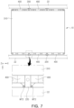
- FIG. 7 is a diagram illustrating coupling of the support member 200 of the battery module 10 to the pack housing 20.
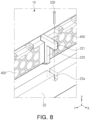
- FIG. 8 is a diagram illustrating coupling of the support member 200 of the battery module 10 to the pack housing 20. Since the battery module 10 described with reference to FIGS. 6 to 8 corresponds to the battery module 10 described above with reference to FIGS. 1 to 5 , redundant descriptions may be omitted.
- the battery pack 1 may include a plurality of battery modules 10 and the pack housing 20 accommodating the plurality of battery modules 10.
- the plurality of battery modules 10 may be accommodated inside the pack housing 20 and electrically connected to each other.
- the pack housing 20 may include a bottom frame 21 on which the plurality of battery modules 10 are arranged and a side frame 22 facing the side of the battery module 10. Although not shown in FIGS. 6 to 8 , the pack housing 20 may further include a top frame (not shown) covering the top of the battery module 10.
- the bottom frame 21 and the side frame 22 may be connected to each other.
- the top frame (not shown) may be connected to the side frame 22 and cover an internal space of the pack housing 20.
- a plurality of side frames 22 may be disposed on a top surface of the bottom frame 21.
- a plurality of side frames 22 may be arranged to be spaced apart from each other on the bottom frame 21 in the first direction (the X-axis direction).
- One of the plurality of side frames 22 may be disposed at the edge of the bottom frame 21 to form the side of the pack housing 20, and the other thereof may be disposed to partition the internal space of the pack housing 20.
- the battery module 10 may be disposed between two adjacent side frames 22.
- the side frame 22 may face at least one of the plurality of battery modules 10 in the first direction (the X-axis direction).
- a plurality of battery modules 10 may be respectively disposed in spaces partitioned by the side frame 22.
- the battery module 10 may be disposed so that the end cover 400 faces the side frame 22 in the first direction (the X-axis direction).
- the battery module 10 may be coupled to the side frame 22 and fixed inside the pack housing 20.
- the support member 200 protruding in the first direction (the X-axis direction) from the side of the battery module 10 may be mechanically fastened or welded to the pack housing 20, and accordingly, the battery module 10 may be fixed to the pack housing 20.
- a heat dissipation member may be disposed between the bottom frame 21 of the pack housing 20 and the cell assembly 100 of the battery module 10.
- the heat dissipation member may be disposed so that one surface thereof is in contact with the cell assembly 100 and the other surface thereof opposite to the one surface is in contact with the bottom frame 21.
- the heat dissipation member may be provided as a thermally conductive adhesive.
- the heat dissipation member may fill a space between the cell assembly 100 and the bottom frame 21 to enable more active heat transfer by conduction. Accordingly, the heat dissipation efficiency of the battery module 10 or the battery pack 10 may increase.
- the battery module 10 may be fixed inside the pack housing 20.
- a length of the support member 200 in the first direction may be approximately equal to a distance between two adjacent side frames 22 in the first direction (the X-axis direction). Therefore, when the battery module 10 is disposed between the side frames 22, both end portions of the support member 200, that is, the extension portion 220 of the support member 200, may contact the side frame 22.
- a welding point WT2 may be set along a portion where the extension portion 220 of the support member 200 and the side frame 22 contact each other.
- the welding point WT2 may be set to extend in a third direction (a Z-axis direction), which is a height direction of the pack housing 20.
- the third direction (the Z-axis direction) may be perpendicular to both the first direction (the X-axis direction) and the second direction (the Y-axis direction) described above.
- a predetermined gap will be formed between the end cover 400 and the side frame 22, and the welding process may be performed safely and easily using the predetermined gap.
- the coupling structure of the battery module 10 and the pack housing 20 is not limited to the above.
- the battery pack 1 may further include a separate fastening member 230 coupling the battery module 10 to the pack housing 20.
- the extension portion 220 of the support member 200 may include an insertion protrusion 221 protruding in the first direction (the X-axis direction).
- the side frame 22 of the pack housing 20 may include an insertion groove 22a into which the insertion protrusion 221 is inserted.
- the insertion protrusion 221 may be configured to be inserted into the insertion groove 22a in the third direction (the Z-axis direction). Therefore, in the process of receiving the battery module 10 in the pack housing 20, the insertion protrusion 221 may be naturally inserted into the insertion groove 22a.
- the fastening member 230 may pass through the insertion protrusion 221 and be fastened to the insertion groove 22a. Accordingly, the support member 200 may be firmly fixed to the side frame 22.
- the length of the support member 200 in the first direction may be greater than the distance between two adjacent side frames 22 in the first direction (the X-axis direction).
- the insertion protrusion 221 and the insertion groove 22a are not limited to those shown in FIG. 8 .
- the insertion protrusion 221 may be configured to protrude from the extension portion 220 in a direction other than the first direction (the X-axis direction).
- the length of the insertion protrusion 221 in the second direction may be configured to be greater than the length of the extension portion 220 in the second direction (the Y-axis direction).
- the size of the insertion groove 22a may be configured to match the size of the insertion protrusion 221. Accordingly, the battery module 10 may be naturally aligned in the correct position during the process of inserting the insertion protrusion 221 into the insertion groove 22a.
- the size of the insertion groove 22a is not limited to the aforementioned size and, for example, may be greater than the size of the insertion protrusion 221.
- the pack housing 20 may have a structure in which a rigid member traversing the side frame 22 is omitted.
- a number of cross frames are arranged to vertically and horizontally traverse the top surface of the bottom frame of the pack housing for structural rigidity.
- such cross frames may be omitted or the number of the cross frames may be significantly reduced.
- the dead space formed between the cross frames and the battery module 10 due to assembly tolerance may be significantly reduced.
- the structure i.e., the support member 200
- the structure that may instead perform the role of the cross frames mentioned above may be disposed inside the battery module 10 and assembled by stacking with the cell assembly 100, thereby fundamentally preventing the occurrence of the dead space mentioned above. Accordingly, a plurality of battery modules 10 may be intensively arranged within the limited space of the pack housing 20, and the battery pack 1 having high energy density may be implemented.
- the battery pack capable of maintaining structural rigidity, while having high energy density may be implemented.
- the battery module and the battery pack having high structural stability may be provided by disposing the support member between a plurality of battery cells.
- the large battery module may be disposed within a limited space inside the battery pack.
Landscapes
- Chemical & Material Sciences (AREA)
- Chemical Kinetics & Catalysis (AREA)
- Electrochemistry (AREA)
- General Chemical & Material Sciences (AREA)
- Engineering & Computer Science (AREA)
- Aviation & Aerospace Engineering (AREA)
- Battery Mounting, Suspending (AREA)
Applications Claiming Priority (1)
| Application Number | Priority Date | Filing Date | Title |
|---|---|---|---|
| KR1020220172267A KR20240087000A (ko) | 2022-12-12 | 2022-12-12 | 배터리 모듈 및 이를 포함하는 배터리 팩 |
Publications (1)
| Publication Number | Publication Date |
|---|---|
| EP4386946A1 true EP4386946A1 (fr) | 2024-06-19 |
Family
ID=89122069
Family Applications (1)
| Application Number | Title | Priority Date | Filing Date |
|---|---|---|---|
| EP23214465.9A Pending EP4386946A1 (fr) | 2022-12-12 | 2023-12-05 | Module de batterie et bloc-batterie le comprenant |
Country Status (4)
| Country | Link |
|---|---|
| US (1) | US20240194991A1 (fr) |
| EP (1) | EP4386946A1 (fr) |
| KR (1) | KR20240087000A (fr) |
| CN (1) | CN118198642A (fr) |
Citations (6)
| Publication number | Priority date | Publication date | Assignee | Title |
|---|---|---|---|---|
| EP2325922A1 (fr) * | 2009-11-19 | 2011-05-25 | SB LiMotive Co., Ltd. | Bloc-batterie |
| EP2339664A1 (fr) * | 2009-12-23 | 2011-06-29 | SB LiMotive Co., Ltd. | Bloc-batterie |
| US20170025652A1 (en) * | 2015-07-22 | 2017-01-26 | Ford Global Technologies, Llc | Battery pack endplate |
| US20210288299A1 (en) * | 2020-03-10 | 2021-09-16 | Karma Automotive Llc | Vehicle battery assembly |
| US20210288298A1 (en) * | 2020-03-10 | 2021-09-16 | Karma Automotive Llc | Vehicle battery system |
| CN217934021U (zh) * | 2022-07-28 | 2022-11-29 | 厦门海辰储能科技股份有限公司 | 支撑结构及用电设备 |
-
2022
- 2022-12-12 KR KR1020220172267A patent/KR20240087000A/ko active Pending
-
2023
- 2023-11-22 CN CN202311561243.8A patent/CN118198642A/zh active Pending
- 2023-12-05 EP EP23214465.9A patent/EP4386946A1/fr active Pending
- 2023-12-11 US US18/535,944 patent/US20240194991A1/en active Pending
Patent Citations (6)
| Publication number | Priority date | Publication date | Assignee | Title |
|---|---|---|---|---|
| EP2325922A1 (fr) * | 2009-11-19 | 2011-05-25 | SB LiMotive Co., Ltd. | Bloc-batterie |
| EP2339664A1 (fr) * | 2009-12-23 | 2011-06-29 | SB LiMotive Co., Ltd. | Bloc-batterie |
| US20170025652A1 (en) * | 2015-07-22 | 2017-01-26 | Ford Global Technologies, Llc | Battery pack endplate |
| US20210288299A1 (en) * | 2020-03-10 | 2021-09-16 | Karma Automotive Llc | Vehicle battery assembly |
| US20210288298A1 (en) * | 2020-03-10 | 2021-09-16 | Karma Automotive Llc | Vehicle battery system |
| CN217934021U (zh) * | 2022-07-28 | 2022-11-29 | 厦门海辰储能科技股份有限公司 | 支撑结构及用电设备 |
Also Published As
| Publication number | Publication date |
|---|---|
| CN118198642A (zh) | 2024-06-14 |
| KR20240087000A (ko) | 2024-06-19 |
| US20240194991A1 (en) | 2024-06-13 |
Similar Documents
| Publication | Publication Date | Title |
|---|---|---|
| CN111384335B (zh) | 一种电池包及车辆 | |
| JP5889418B2 (ja) | 信頼性が向上した電池モジュールアセンブリ及びこれを含む中大型電池パック | |
| US7612526B2 (en) | Battery module having coupled cases of adjacent unit batteries | |
| KR101281811B1 (ko) | 구조적 안정성이 향상된 전지팩 | |
| CN111937180B (zh) | 包括内部板的电池模块、包括该电池模块的电池组及车辆 | |
| KR20120074425A (ko) | 전지모듈 및 이를 포함하는 전지팩 | |
| US12015163B2 (en) | Eco-friendly power source such as battery module for a transportation vehicle and method of manufacturing battery module | |
| KR102672588B1 (ko) | 배터리 모듈 및 배터리 팩 | |
| EP4376184B1 (fr) | Bloc-batterie | |
| KR20240012302A (ko) | 배터리 팩 및 이를 포함하는 디바이스 | |
| JP7828545B2 (ja) | 蓄電装置 | |
| EP4372880A1 (fr) | Module de batterie et bloc-batterie le comprenant | |
| JP2023114147A (ja) | 電池パック | |
| EP4266465A1 (fr) | Module de batterie | |
| KR20240012303A (ko) | 전지셀 어셈블리 및 이를 포함하는 전지 팩 | |
| US20240194991A1 (en) | Battery module and battery pack including the same | |
| EP4675803A1 (fr) | Élément de bande, module de batterie, bloc-batterie | |
| US20260142293A1 (en) | Eco-friendly power source such as battery module for a transportation vehicle | |
| EP4362183A1 (fr) | Module de batterie | |
| EP4738590A1 (fr) | Module de batterie, et bloc-batterie et véhicule le comprenant | |
| EP4485626A1 (fr) | Dispositif de batterie comprenant un élément de blocage thermique et une structure de fixation | |
| WO2025241095A1 (fr) | Élément de batterie, batterie, dispositif électrique et dispositif de stockage d'énergie | |
| WO2025241093A1 (fr) | Élément de batterie, batterie, appareil électrique et appareil de stockage d'énergie | |
| KR20250143431A (ko) | 버스바 조립체를 포함하는 배터리 모듈 및 이를 포함하는 배터리 팩 | |
| CN120419046A (zh) | 电池组和包括该电池组的车辆 |
Legal Events
| Date | Code | Title | Description |
|---|---|---|---|
| PUAI | Public reference made under article 153(3) epc to a published international application that has entered the european phase |
Free format text: ORIGINAL CODE: 0009012 |
|
| STAA | Information on the status of an ep patent application or granted ep patent |
Free format text: STATUS: THE APPLICATION HAS BEEN PUBLISHED |
|
| AK | Designated contracting states |
Kind code of ref document: A1 Designated state(s): AL AT BE BG CH CY CZ DE DK EE ES FI FR GB GR HR HU IE IS IT LI LT LU LV MC ME MK MT NL NO PL PT RO RS SE SI SK SM TR |
|
| STAA | Information on the status of an ep patent application or granted ep patent |
Free format text: STATUS: REQUEST FOR EXAMINATION WAS MADE |
|
| 17P | Request for examination filed |
Effective date: 20241218 |