EP4387002A1 - Connecteur de puissance avec un joint conducteur - Google Patents
Connecteur de puissance avec un joint conducteur Download PDFInfo
- Publication number
- EP4387002A1 EP4387002A1 EP22214025.3A EP22214025A EP4387002A1 EP 4387002 A1 EP4387002 A1 EP 4387002A1 EP 22214025 A EP22214025 A EP 22214025A EP 4387002 A1 EP4387002 A1 EP 4387002A1
- Authority
- EP
- European Patent Office
- Prior art keywords
- conductive seal
- housing
- elastomeric conductive
- cavity
- shielding element
- Prior art date
- Legal status (The legal status is an assumption and is not a legal conclusion. Google has not performed a legal analysis and makes no representation as to the accuracy of the status listed.)
- Pending
Links
Images

Classifications
-
- H—ELECTRICITY
- H01—ELECTRIC ELEMENTS
- H01R—ELECTRICALLY-CONDUCTIVE CONNECTIONS; STRUCTURAL ASSOCIATIONS OF A PLURALITY OF MUTUALLY-INSULATED ELECTRICAL CONNECTING ELEMENTS; COUPLING DEVICES; CURRENT COLLECTORS
- H01R13/00—Details of coupling devices of the kinds covered by groups H01R12/70 or H01R24/00 - H01R33/00
- H01R13/648—Protective earth or shield arrangements on coupling devices, e.g. anti-static shielding
- H01R13/658—High frequency shielding arrangements, e.g. against EMI [Electro-Magnetic Interference] or EMP [Electro-Magnetic Pulse]
- H01R13/6598—Shield material
- H01R13/6599—Dielectric material made conductive, e.g. plastic material coated with metal
-
- H—ELECTRICITY
- H01—ELECTRIC ELEMENTS
- H01R—ELECTRICALLY-CONDUCTIVE CONNECTIONS; STRUCTURAL ASSOCIATIONS OF A PLURALITY OF MUTUALLY-INSULATED ELECTRICAL CONNECTING ELEMENTS; COUPLING DEVICES; CURRENT COLLECTORS
- H01R13/00—Details of coupling devices of the kinds covered by groups H01R12/70 or H01R24/00 - H01R33/00
- H01R13/46—Bases; Cases
- H01R13/52—Dustproof, splashproof, drip-proof, waterproof, or flameproof cases
- H01R13/5205—Sealing means between cable and housing, e.g. grommet
- H01R13/5208—Sealing means between cable and housing, e.g. grommet having at least two cable receiving openings
-
- H—ELECTRICITY
- H01—ELECTRIC ELEMENTS
- H01R—ELECTRICALLY-CONDUCTIVE CONNECTIONS; STRUCTURAL ASSOCIATIONS OF A PLURALITY OF MUTUALLY-INSULATED ELECTRICAL CONNECTING ELEMENTS; COUPLING DEVICES; CURRENT COLLECTORS
- H01R13/00—Details of coupling devices of the kinds covered by groups H01R12/70 or H01R24/00 - H01R33/00
- H01R13/46—Bases; Cases
- H01R13/52—Dustproof, splashproof, drip-proof, waterproof, or flameproof cases
- H01R13/5216—Dustproof, splashproof, drip-proof, waterproof, or flameproof cases characterised by the sealing material, e.g. gels or resins
-
- H—ELECTRICITY
- H01—ELECTRIC ELEMENTS
- H01R—ELECTRICALLY-CONDUCTIVE CONNECTIONS; STRUCTURAL ASSOCIATIONS OF A PLURALITY OF MUTUALLY-INSULATED ELECTRICAL CONNECTING ELEMENTS; COUPLING DEVICES; CURRENT COLLECTORS
- H01R9/00—Structural associations of a plurality of mutually-insulated electrical connecting elements, e.g. terminal strips or terminal blocks; Terminals or binding posts mounted upon a base or in a case; Bases therefor
- H01R9/03—Connectors arranged to contact a plurality of the conductors of a multiconductor cable, e.g. tapping connections
- H01R9/05—Connectors arranged to contact a plurality of the conductors of a multiconductor cable, e.g. tapping connections for coaxial cables
- H01R9/0527—Connection to outer conductor by action of a resilient member, e.g. spring
-
- H—ELECTRICITY
- H01—ELECTRIC ELEMENTS
- H01R—ELECTRICALLY-CONDUCTIVE CONNECTIONS; STRUCTURAL ASSOCIATIONS OF A PLURALITY OF MUTUALLY-INSULATED ELECTRICAL CONNECTING ELEMENTS; COUPLING DEVICES; CURRENT COLLECTORS
- H01R13/00—Details of coupling devices of the kinds covered by groups H01R12/70 or H01R24/00 - H01R33/00
- H01R13/46—Bases; Cases
- H01R13/52—Dustproof, splashproof, drip-proof, waterproof, or flameproof cases
- H01R13/5205—Sealing means between cable and housing, e.g. grommet
-
- H—ELECTRICITY
- H01—ELECTRIC ELEMENTS
- H01R—ELECTRICALLY-CONDUCTIVE CONNECTIONS; STRUCTURAL ASSOCIATIONS OF A PLURALITY OF MUTUALLY-INSULATED ELECTRICAL CONNECTING ELEMENTS; COUPLING DEVICES; CURRENT COLLECTORS
- H01R13/00—Details of coupling devices of the kinds covered by groups H01R12/70 or H01R24/00 - H01R33/00
- H01R13/648—Protective earth or shield arrangements on coupling devices, e.g. anti-static shielding
- H01R13/658—High frequency shielding arrangements, e.g. against EMI [Electro-Magnetic Interference] or EMP [Electro-Magnetic Pulse]
- H01R13/6581—Shield structure
- H01R13/6582—Shield structure with resilient means for engaging mating connector
-
- H—ELECTRICITY
- H01—ELECTRIC ELEMENTS
- H01R—ELECTRICALLY-CONDUCTIVE CONNECTIONS; STRUCTURAL ASSOCIATIONS OF A PLURALITY OF MUTUALLY-INSULATED ELECTRICAL CONNECTING ELEMENTS; COUPLING DEVICES; CURRENT COLLECTORS
- H01R2201/00—Connectors or connections adapted for particular applications
- H01R2201/26—Connectors or connections adapted for particular applications for vehicles
Definitions
- the disclosure below relates to the field of power connectors. More particularly, this disclosure relates to power connectors equipped with electromagnetic shielding. Such power connectors can be used in motor vehicles.
- the connectors comprising a global shielding and the connectors in which the shielding is provided by a shielding continuity through individual shielded wires.
- these types of connectors are usually sealed against ingress of water. Then, depending on the shielding technology (global or through individual shielded wires), the shielding elements are placed inside or outside the sealed area.
- patent document EP3155692A1 discloses a connector with shielding elements inside the sealed area and the patent document FR3032835A1 discloses a connector with shielding elements outside the sealed area.
- the present disclosure is intended to provide a solution that at least partially reduces these drawbacks.
- this connector it is proposed a power connector according to claim 1. Thanks to this power connector, the shielding layer of individual shielded wires are connected, via the elastomeric conductive seal to the outer shielding elements.
- this connector can be used for both shielding technologies: global or through individual shielded wires.
- the connector interface remains compatible with a single reference of counter-connector. It is not necessary to manufacture two counter-connectors for use in each of these two shielding technologies.
- this electrical connector possibly comprises one or more of the features mentioned in claims 2 to 6, each one of these features being considered independently of each other or in combination of one or several others.
- this method possibly comprises one or more of the features mentioned in claims 8 to 10, each one of these features being considered independently of each other or in combination of one or several others.
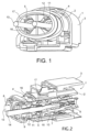
- FIG. 1 An example of an embodiment of a power connector 1 is shown in Figures 1 to 3 .
- the power connector 1 is a 2-way female connector, but this disclosure can be transposed to other types of connectors.
- adjectives such as “rear”, “front”, etc. refer to the mating direction of the connector 1, the front side corresponding to the mating interface of the connector 1 with a counter-connector.
- the connector 1 is a cable connector. It comprises in particular a housing 2, a mate assist system 3, an outer shielding element 4 (which can be formed by one or several parts), two ferules 5, two female terminals 6, two front single-wire seals 7, two seal retainers 8, two rear single-wire seals 9, a global seal 10 and an elastomeric conductive seal 11.
- the housing 2, the mate assist system 3 and the seal retainers 9 are made of a dielectric material (for example they are made by molding).
- the outer shielding element 4 and the ferules 5 are made of a conductive material (for example the ferules 5 are made by deep-drawing of a sheet metal).
- the female terminals 6 are made for example of copper or a copper alloy (although, other conductive metals can be used, such as aluminum for example).
- the front single-wire seals 7, the rear single-wire seals 9 and the global seal 10 are made of elastomeric material.
- the elastomeric conductive seal 11 is made of elastomeric material with conductive fillers (For example, the elastomeric material is a silicone or fluorosilicone, and the fillers may comprise carbon, graphite, silver and/or copper particles).
- the elastomeric conductive seal 11 is made of a graphite mixed dry silicone.
- Such an elastomeric conductive seal 11 has properties which are suitable for sealing the connector 1, as well as a suitable electrical conductivity.
- the elastomeric material with conductive fillers is chosen to achieve a resistance of less than 100mOhms, and more advantageously less than 50mOhms (for example, about 30mOhms). It has been confirmed that such a material does not reduce the performances of the shielding properties (attenuation) of the overall connector 1.
- the housing 2 comprises two cavities 12, each one accommodating one female terminal 6. Each female terminal 6 is mechanically attached and electrically linked to a shielded cable 13.
- Each shielded cable 13 comprises, from the outside in, an outer insulating sheath 14, a shielding layer 15 (for example a shielding braid), an inner insulating sheath and a core wire (not shown).
- a ferule 5 is mounted on a stripped area of each shielded cable 13, on which a portion of the outer insulating sheath 14 is removed to expose the shielding layer 15.
- a rear single wire seal 9 is mounted on each shielded cable 13, on a rear portion of this stripped area.
- Each rear single-wire seal 9 seals a cavity 12 between an inner surface of the housing 2 and the outer insulating sheath 14 of a shielded cable 13.
- a front single wire seal 7 is mounted on each shielded cable 13, between the stripped area and a female terminal 6.
- each front single wire seal 7 is maintained on a shielded cable by a crimping portion of a female terminal 6.
- Each front single-wire seal 7 seals a cavity 12 between an inner surface of the housing 2 and the inner insulating sheath of a shielded cable 13. Accordingly, each cavity 12, as in prior art configurations, is sealed at the front and at the rear, respectively by a front single-wire seal 7 and a rear single-wire seal 9.
- each cavity 12 is only open at its rear and front ends. But, further in this embodiment example, each cavity 12 has a peripheral wall 16 comprising passages 17. In other words, passages 17 are made in the housing 2, between the outer surface and the inner surface of the peripheral wall 16 of each cavity 12. Then, an elastomeric conductive seal 11 is required to complete the sealing of the cavity 12 at the passages 17. Further, the elastomeric conductive seal 11 provides an electrical continuity between the outer shielding element 4 and the ferules 5.
- each ferule 5 has a fixation portion 18 and funnel portion 19 (see Figure 3 ).
- the funnel portion 19 serves to guide a free end of the shielded cable 13 towards and in the fixation portion 18.
- the funnel portion 19 also provides a smoother and larger electrical contact area that the fixation portion 18. This improves the electrical contact between the elastomeric conductive seal 11 and the ferule 5.
- the fixation portion 18 is tightly held on the stripped portion of the shielded cable 13 so as to establish an electrical contact and connection between the shielding layer 15 of the shielded cable 13.
- the elastomeric conductive seal 11 is in electrical contact both with the with outer shielding element 4 and the funnel portion 19, which is itself electrically connected to the fixation portion 18. Therefore, an electrical continuity is established between the outer shielding element 4 and the shielding layer 15 of the shielded cable 13 through the passages 17 via the elastomeric conductive seal 11.
- the elastomeric conductive seal 11 has an essentially oval shape.
- This essentially oval shape forms a closed loop or ring.
- This ring has an outer circumferential surface 20 and an inner surface 21.
- the outer circumferential surface 20 faces radially outward (of the ring shape) and is smooth.
- the inner surface 21 is essentially opposite the outer circumferential surface 20, faces radially inward and includes two crenelated sections 22 on which contacting projections 23 extend radially inward from the inner surface 21.
- the contacting projections 23 form a single piece with the ring.
- each crenelated section 22 comprises five contacting projections 23.
- the elastomeric conductive seal 11 is placed on the outer surface of the housing 2, with one contacting projection 23 in each passage 17.
- the elastomeric conductive seal 11 is shared by the two cavities 12 of the connector 1, but the elastomeric conductive seal 11 comprises one crenelated section 22 for each cavity 12.
- the elastomeric conductive seal 11 is essentially inserted between the outer surface of the housing 2 and the outer shielding element 4, even though each contacting projection 23 penetrates, through a passage 17, in a cavity 12 to make an electrical contact with the corresponding ferule 5.
- the elastomeric conductive seal 11 has connection means (i. e. contacting projection 23) passing through at least one passage 17, and such connection means electrically connects the shielding layer 15 to at least one outer shielding element 4.
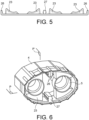
- the elastomeric conductive seal 11 is manufactured as an open strip. This open strip can be bent so as to form a ring (see Figure 6 ). Then, the elastomeric conductive seal 11 has four contacting projections 23, as well as fixation projections 26, 27. The fixation projections 26, 27 are intended to be inserted in opposite openings or notches made in the housing 2. More particularly, the elastomeric conductive seal 11 has two end fixation projections 26 each respectively located at a free end of the open strip and one central fixation projection 27 located essentially in the middle of the open strip. When inserted in an opening or a notch, the two end fixation projections 26 (which are each respectively equivalent to half of the central fixation projection 27) maintain the strip as a ring.
- Each contacting projection 23 penetrates through a passage 17 to establish an electrical contact with a ferule 5.
- the contacting projections 23 are symmetrically arranged with regard to a plane P (horizontal in Figure 6 ) passing through the longitudinal axis of the two ferules 5. They are also symmetrically arranged with regard to a plane P' (vertical in Figure 6 ) passing through the end fixation projections 26, 27.
- the elastomeric conductive seal 11 shown in Figure 5 and 6 is easier to manufacture and to assemble on the housing 2, than the one shown in figure 4 .
- the elastomeric conductive seal 11 shown in Figure 5 and 6 is essentially inserted between the outer surface of the housing 2 and the outer shielding element 4 as described for the previous embodiment (the one shown in Figure 4 ).
Landscapes
- Chemical & Material Sciences (AREA)
- Dispersion Chemistry (AREA)
- Connector Housings Or Holding Contact Members (AREA)
Priority Applications (1)
| Application Number | Priority Date | Filing Date | Title |
|---|---|---|---|
| EP22214025.3A EP4387002A1 (fr) | 2022-12-15 | 2022-12-15 | Connecteur de puissance avec un joint conducteur |
Applications Claiming Priority (1)
| Application Number | Priority Date | Filing Date | Title |
|---|---|---|---|
| EP22214025.3A EP4387002A1 (fr) | 2022-12-15 | 2022-12-15 | Connecteur de puissance avec un joint conducteur |
Publications (1)
| Publication Number | Publication Date |
|---|---|
| EP4387002A1 true EP4387002A1 (fr) | 2024-06-19 |
Family
ID=84537428
Family Applications (1)
| Application Number | Title | Priority Date | Filing Date |
|---|---|---|---|
| EP22214025.3A Pending EP4387002A1 (fr) | 2022-12-15 | 2022-12-15 | Connecteur de puissance avec un joint conducteur |
Country Status (1)
| Country | Link |
|---|---|
| EP (1) | EP4387002A1 (fr) |
Citations (8)
| Publication number | Priority date | Publication date | Assignee | Title |
|---|---|---|---|---|
| US20060110977A1 (en) * | 2004-11-24 | 2006-05-25 | Roger Matthews | Connector having conductive member and method of use thereof |
| US7393218B1 (en) * | 2007-03-19 | 2008-07-01 | Lear Corporation | Connector assembly with overmolded shielded housing |
| FR2981210A1 (fr) * | 2011-10-10 | 2013-04-12 | Leoni Wiring Systems France | Dispositif de raccordement d'un cable blinde sur un boitier |
| US20150288108A1 (en) * | 2014-04-03 | 2015-10-08 | Cooper Technologies Company | Grounding for Electrical Connectors |
| FR3032835A1 (fr) | 2015-02-17 | 2016-08-19 | Delphi Int Operations Luxembourg Sarl | Procede de fixation d'un dispositif de passage de conducteur electrique a travers une paroi et dispositif pour la mise en œuvre de ce procede |
| EP3155692A1 (fr) | 2014-06-12 | 2017-04-19 | Delphi International Operations Luxembourg S.à r.l. | Connecteur électrique blindé et son procédé de fabrication |
| US20200280150A1 (en) * | 2019-02-28 | 2020-09-03 | J.S.T. Corporation | Method for electromagnetic interference (emi) protection for a connector assembly using a conductive seal |
| US11450990B2 (en) * | 2019-02-25 | 2022-09-20 | J.S.T. Corporation | Method for shielding and grounding a connector assembly from electromagnetic interference (EMI) using a male/female joint stamped shield and conductive seal |
-
2022
- 2022-12-15 EP EP22214025.3A patent/EP4387002A1/fr active Pending
Patent Citations (8)
| Publication number | Priority date | Publication date | Assignee | Title |
|---|---|---|---|---|
| US20060110977A1 (en) * | 2004-11-24 | 2006-05-25 | Roger Matthews | Connector having conductive member and method of use thereof |
| US7393218B1 (en) * | 2007-03-19 | 2008-07-01 | Lear Corporation | Connector assembly with overmolded shielded housing |
| FR2981210A1 (fr) * | 2011-10-10 | 2013-04-12 | Leoni Wiring Systems France | Dispositif de raccordement d'un cable blinde sur un boitier |
| US20150288108A1 (en) * | 2014-04-03 | 2015-10-08 | Cooper Technologies Company | Grounding for Electrical Connectors |
| EP3155692A1 (fr) | 2014-06-12 | 2017-04-19 | Delphi International Operations Luxembourg S.à r.l. | Connecteur électrique blindé et son procédé de fabrication |
| FR3032835A1 (fr) | 2015-02-17 | 2016-08-19 | Delphi Int Operations Luxembourg Sarl | Procede de fixation d'un dispositif de passage de conducteur electrique a travers une paroi et dispositif pour la mise en œuvre de ce procede |
| US11450990B2 (en) * | 2019-02-25 | 2022-09-20 | J.S.T. Corporation | Method for shielding and grounding a connector assembly from electromagnetic interference (EMI) using a male/female joint stamped shield and conductive seal |
| US20200280150A1 (en) * | 2019-02-28 | 2020-09-03 | J.S.T. Corporation | Method for electromagnetic interference (emi) protection for a connector assembly using a conductive seal |
Similar Documents
| Publication | Publication Date | Title |
|---|---|---|
| US11664629B2 (en) | Assembly comprising a connector and a cable | |
| US3670293A (en) | Shielded wire connectors | |
| US7601029B2 (en) | Electric connector assembly kit and shielded cable harness | |
| CN108631095B (zh) | 触头载体、电触头单元及制造现成的电缆的方法 | |
| KR102765171B1 (ko) | 자동차 적용을 위한 커넥터 | |
| KR20250056843A (ko) | 자동차 적용을 위한 커넥터 및 조립체 | |
| EP1548899A1 (fr) | Connecteur blindé | |
| KR20190034116A (ko) | 전기 콘택 디바이스, 전기 연결 유닛 및 전기 케이블 조립하기 위한 방법 | |
| US12100915B2 (en) | Shielded electrical connector for automotive applications and method of assembling thereof | |
| US9928939B1 (en) | Device and method for splicing shielded wire cables | |
| EP3783754A1 (fr) | Connecteur pour applications automobiles | |
| US20220115822A1 (en) | Connector, and connector structure | |
| JP2018181456A (ja) | 内導体端子及びシールドコネクタ | |
| TW201212428A (en) | Coaxial connector and substrate connector | |
| CN112838391A (zh) | 具有电介质分隔肋的阻抗控制连接器 | |
| EP0125760A1 (fr) | Connecteur à broches ayant une enveloppe blindée | |
| EP1744409A2 (fr) | Connecteur blindé et procédé pour le connecter avec un câble blindé | |
| EP4387002A1 (fr) | Connecteur de puissance avec un joint conducteur | |
| JP7128511B2 (ja) | シールドコネクタ | |
| EP4372930A1 (fr) | Connecteur avec une plaque de mise à la terre commune | |
| JP2011060426A (ja) | コネクタ | |
| CN114389063B (zh) | 带有屏蔽双绞线电缆的电缆线束组件 | |
| KR102474333B1 (ko) | 차량용 패키지커넥터 | |
| JP2011060425A (ja) | シールドコネクタ | |
| US20220200171A1 (en) | Communication cable with connector and connector assembly |
Legal Events
| Date | Code | Title | Description |
|---|---|---|---|
| PUAI | Public reference made under article 153(3) epc to a published international application that has entered the european phase |
Free format text: ORIGINAL CODE: 0009012 |
|
| STAA | Information on the status of an ep patent application or granted ep patent |
Free format text: STATUS: THE APPLICATION HAS BEEN PUBLISHED |
|
| AK | Designated contracting states |
Kind code of ref document: A1 Designated state(s): AL AT BE BG CH CY CZ DE DK EE ES FI FR GB GR HR HU IE IS IT LI LT LU LV MC ME MK MT NL NO PL PT RO RS SE SI SK SM TR |
|
| RAP1 | Party data changed (applicant data changed or rights of an application transferred) |
Owner name: APTIV TECHNOLOGIES AG |
|
| STAA | Information on the status of an ep patent application or granted ep patent |
Free format text: STATUS: REQUEST FOR EXAMINATION WAS MADE |
|
| 17P | Request for examination filed |
Effective date: 20241218 |