EP4387080A1 - Commande d'entraînement à vitesse variable - Google Patents
Commande d'entraînement à vitesse variable Download PDFInfo
- Publication number
- EP4387080A1 EP4387080A1 EP22306903.0A EP22306903A EP4387080A1 EP 4387080 A1 EP4387080 A1 EP 4387080A1 EP 22306903 A EP22306903 A EP 22306903A EP 4387080 A1 EP4387080 A1 EP 4387080A1
- Authority
- EP
- European Patent Office
- Prior art keywords
- current
- electric motor
- current signals
- determining
- signals
- Prior art date
- Legal status (The legal status is an assumption and is not a legal conclusion. Google has not performed a legal analysis and makes no representation as to the accuracy of the status listed.)
- Pending
Links
Images



Classifications
-
- H—ELECTRICITY
- H02—GENERATION; CONVERSION OR DISTRIBUTION OF ELECTRIC POWER
- H02P—CONTROL OR REGULATION OF ELECTRIC MOTORS, ELECTRIC GENERATORS OR DYNAMO-ELECTRIC CONVERTERS; CONTROLLING TRANSFORMERS, REACTORS OR CHOKE COILS
- H02P6/00—Arrangements for controlling synchronous motors or other dynamo-electric motors using electronic commutation dependent on the rotor position; Electronic commutators therefor
- H02P6/08—Arrangements for controlling the speed or torque of a single motor
-
- H—ELECTRICITY
- H02—GENERATION; CONVERSION OR DISTRIBUTION OF ELECTRIC POWER
- H02P—CONTROL OR REGULATION OF ELECTRIC MOTORS, ELECTRIC GENERATORS OR DYNAMO-ELECTRIC CONVERTERS; CONTROLLING TRANSFORMERS, REACTORS OR CHOKE COILS
- H02P27/00—Arrangements or methods for the control of AC motors characterised by the kind of supply voltage
- H02P27/04—Arrangements or methods for the control of AC motors characterised by the kind of supply voltage using variable-frequency supply voltage, e.g. inverter or converter supply voltage
- H02P27/06—Arrangements or methods for the control of AC motors characterised by the kind of supply voltage using variable-frequency supply voltage, e.g. inverter or converter supply voltage using DC to AC converters or inverters
- H02P27/08—Arrangements or methods for the control of AC motors characterised by the kind of supply voltage using variable-frequency supply voltage, e.g. inverter or converter supply voltage using DC to AC converters or inverters with pulse width modulation
- H02P27/12—Arrangements or methods for the control of AC motors characterised by the kind of supply voltage using variable-frequency supply voltage, e.g. inverter or converter supply voltage using DC to AC converters or inverters with pulse width modulation pulsing by guiding the flux vector, current vector or voltage vector on a circle or a closed curve, e.g. for direct torque control
-
- H—ELECTRICITY
- H02—GENERATION; CONVERSION OR DISTRIBUTION OF ELECTRIC POWER
- H02P—CONTROL OR REGULATION OF ELECTRIC MOTORS, ELECTRIC GENERATORS OR DYNAMO-ELECTRIC CONVERTERS; CONTROLLING TRANSFORMERS, REACTORS OR CHOKE COILS
- H02P27/00—Arrangements or methods for the control of AC motors characterised by the kind of supply voltage
- H02P27/04—Arrangements or methods for the control of AC motors characterised by the kind of supply voltage using variable-frequency supply voltage, e.g. inverter or converter supply voltage
- H02P27/06—Arrangements or methods for the control of AC motors characterised by the kind of supply voltage using variable-frequency supply voltage, e.g. inverter or converter supply voltage using DC to AC converters or inverters
- H02P27/08—Arrangements or methods for the control of AC motors characterised by the kind of supply voltage using variable-frequency supply voltage, e.g. inverter or converter supply voltage using DC to AC converters or inverters with pulse width modulation
-
- H—ELECTRICITY
- H02—GENERATION; CONVERSION OR DISTRIBUTION OF ELECTRIC POWER
- H02P—CONTROL OR REGULATION OF ELECTRIC MOTORS, ELECTRIC GENERATORS OR DYNAMO-ELECTRIC CONVERTERS; CONTROLLING TRANSFORMERS, REACTORS OR CHOKE COILS
- H02P21/00—Arrangements or methods for the control of electric machines by vector control, e.g. by control of field orientation
- H02P21/14—Estimation or adaptation of machine parameters, e.g. flux, current or voltage
-
- H—ELECTRICITY
- H02—GENERATION; CONVERSION OR DISTRIBUTION OF ELECTRIC POWER
- H02P—CONTROL OR REGULATION OF ELECTRIC MOTORS, ELECTRIC GENERATORS OR DYNAMO-ELECTRIC CONVERTERS; CONTROLLING TRANSFORMERS, REACTORS OR CHOKE COILS
- H02P21/00—Arrangements or methods for the control of electric machines by vector control, e.g. by control of field orientation
- H02P21/22—Current control, e.g. using a current control loop
-
- H—ELECTRICITY
- H02—GENERATION; CONVERSION OR DISTRIBUTION OF ELECTRIC POWER
- H02P—CONTROL OR REGULATION OF ELECTRIC MOTORS, ELECTRIC GENERATORS OR DYNAMO-ELECTRIC CONVERTERS; CONTROLLING TRANSFORMERS, REACTORS OR CHOKE COILS
- H02P23/00—Arrangements or methods for the control of AC motors characterised by a control method other than vector control
- H02P23/0004—Control strategies in general, e.g. linear type, e.g. P, PI, PID, using robust control
-
- H—ELECTRICITY
- H02—GENERATION; CONVERSION OR DISTRIBUTION OF ELECTRIC POWER
- H02P—CONTROL OR REGULATION OF ELECTRIC MOTORS, ELECTRIC GENERATORS OR DYNAMO-ELECTRIC CONVERTERS; CONTROLLING TRANSFORMERS, REACTORS OR CHOKE COILS
- H02P23/00—Arrangements or methods for the control of AC motors characterised by a control method other than vector control
- H02P23/04—Arrangements or methods for the control of AC motors characterised by a control method other than vector control specially adapted for damping motor oscillations, e.g. for reducing hunting
-
- H—ELECTRICITY
- H02—GENERATION; CONVERSION OR DISTRIBUTION OF ELECTRIC POWER
- H02P—CONTROL OR REGULATION OF ELECTRIC MOTORS, ELECTRIC GENERATORS OR DYNAMO-ELECTRIC CONVERTERS; CONTROLLING TRANSFORMERS, REACTORS OR CHOKE COILS
- H02P23/00—Arrangements or methods for the control of AC motors characterised by a control method other than vector control
- H02P23/14—Estimation or adaptation of motor parameters, e.g. rotor time constant, flux, speed, current or voltage
-
- H—ELECTRICITY
- H02—GENERATION; CONVERSION OR DISTRIBUTION OF ELECTRIC POWER
- H02P—CONTROL OR REGULATION OF ELECTRIC MOTORS, ELECTRIC GENERATORS OR DYNAMO-ELECTRIC CONVERTERS; CONTROLLING TRANSFORMERS, REACTORS OR CHOKE COILS
- H02P27/00—Arrangements or methods for the control of AC motors characterised by the kind of supply voltage
- H02P27/04—Arrangements or methods for the control of AC motors characterised by the kind of supply voltage using variable-frequency supply voltage, e.g. inverter or converter supply voltage
- H02P27/06—Arrangements or methods for the control of AC motors characterised by the kind of supply voltage using variable-frequency supply voltage, e.g. inverter or converter supply voltage using DC to AC converters or inverters
- H02P27/08—Arrangements or methods for the control of AC motors characterised by the kind of supply voltage using variable-frequency supply voltage, e.g. inverter or converter supply voltage using DC to AC converters or inverters with pulse width modulation
- H02P27/085—Arrangements or methods for the control of AC motors characterised by the kind of supply voltage using variable-frequency supply voltage, e.g. inverter or converter supply voltage using DC to AC converters or inverters with pulse width modulation wherein the PWM mode is adapted on the running conditions of the motor, e.g. the switching frequency
Definitions
- This invention relates to a method for controlling a variable speed drive driving a three-phase electric motor.
- variable speed drive allows modifying a frequency, amplitude and/or phase of an electric signal provided by an electric network in order to control an electric motor.
- the variable speed drive usually comprises a rectifier stage, a DC-link stage and an inverter stage.
- the inverter stage may comprise six switches controlled using a pulse width modulation, PWM, function.
- PWM pulse width modulation
- the PWM function is determined based on a control law enabling to drive the electric motor at a desired operating point while seeking to balance the voltages applied on the different windings of the electric motor for reducing component aging and thermal problems of the electric motor.
- the present description aims at improving operation of electric motor, in particular with regards to aging of components.
- An object of the present disclosure is to propose a method for controlling a variable speed drive driving a three-phase electric motor, the variable speed drive comprising a pulse width modulation, PWM, controller, an inverter and a DC-link adapted to supply the inverter with a significantly continuous voltage, wherein :
- the PWM signals applied based on an amended control law therefore allows reducing a current offset in relation to a zero-current of at least one winding of the electric motor or reducing a current misbalance between the windings of the electric motor.
- Reducing a current offset in relation to a zero-current value in a specific winding of an electric motor allows reducing inductance saturation probability of the specific winding of the electric motor, therefore reducing the torque ripple of the electric motor.
- Reducing a current misbalance between the windings of the electric motor allows mitigating the electric motor overheating and therefore reducing the electrical and/or mechanical damages induced by an undesired overheating.
- determining a current parameter comprises determining a current offset of at least one winding of the electric motor and a current misbalance between windings of the electric motor.
- determining the current misbalance between windings of the electric motor comprises:
- the current vector angle ⁇ in ⁇ frame is estimated based on a Phase-Locked Loop, PLL, or is determined based on the magnetic flux vector angle of the electric motor determined by the variable speed drive.
- PLL Phase-Locked Loop
- the current parameter comprises a current offset of each winding of the electric motor.
- the current parameter comprises a current offset of a specific winding of the electric motor and wherein determining a current offset of the specific winding comprises determining an average value of the current signal of the specific winding.
- the current parameter comprises a current offset of a specific winding of the electric motor and wherein determining a current offset of the specific winding comprises applying a digital low-pass filter on the measured current signal of the specific winding of the electric motor.
- determining an amended control law comprises determining a proportional factor and an integral factor of a proportional-integer, PI, regulator for canceling the determined current parameter.
- a transformer is disposed between the variable speed drive and the electric motor such that the variable speed drive drives the electric motor through the transformer.
- the present disclosure also presents:
- the example method according to the present disclosure therefore allows at least reducing inductance saturation probability of a specific winding of the electric motor, or reducing the torque ripple of the electric motor and the electrical and/or mechanical damages induced by an undesired overheating, and therefore allow reducing the component aging of the electric motor.
- the disclosure applies to a method for controlling a variable speed drive driving an electric motor.
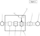
- An example of an electric circuit whereby the method could be applied is described below with reference to figure 1 .
- the components represented by dotted lines are optional.
- the electric circuit comprises an electric power source 2, a variable speed drive 3 and an electric motor 4.
- the electric power source 2 may correspond to a battery supplying a direct voltage DC, or to an electric network supplying either an alternating voltage AC, or a direct voltage DC.
- the alternating voltage AC may for example comprise two or three phases.
- the power source 2 may, for example, be a three-phase electric network as illustrated in figure 1 .
- An electric motor 4 should be understood in this disclosure as any kind of electric motors which may be driven by a variable speed drive.
- the electric motor may be a synchronous or an asynchronous electric motor, for example a reluctance motor or a permanent magnet synchronous motor.
- variable speed drive 3 should be understood in this disclosure as an electronic, electrical, virtual or software implemented control unit for an electric motor.
- a variable speed drive may control an electric motor 4 using an electric or electronic command and in particular may apply a determined voltage to the motor.
- the variable speed drive may comprise a rectifier 31.
- the rectifier 31 is intended to convert an alternating voltage AC supplied by the power source 2 into a direct voltage DC.
- the rectifier 31 is an option as represented by the dotted lines in figure 1 .
- a rectifier 31 may be a diode rectifier for rectifying an alternating voltage supplied by the electric power source 2.
- the variable speed drive 3 comprises a DC-link 32.
- the DC-link may be defined as a circuit configured to stabilize the voltage of a direct power bus, DC bus, supplying an inverter 33.
- the DC-link 32 is adapted to supply the inverter 33 with a significantly continuous voltage,
- the DC-link 32 is connected, in one side, either to the rectifier 31 when the variable speed drive comprises a rectifier 31, or to the electric power source 2, and in another side, to the inverter 33 as illustrated in figure 1 .
- the inverter 33 is intended to cut off the voltage supplied by the DC-link into a variable voltage to control the electric motor 4.
- a subpart of the electric circuit 1 illustrating more precisely an example of inverter 33 is illustrated in figure 2 .
- the inverter 33 comprises 3 legs. Each leg is connected on one side to a positive bus of the significantly continuous voltage and on another side to a negative bus of the significantly continuous voltage.
- the inverter 33 comprises 6 switches 330.
- Each leg of the inverter comprises a top switch 330t and a bottom switch 330b.
- a connection between a leg and a winding of the electric motor 4 is located between the top switch 330t and the bottom switch 330b as illustrated in figure 2 .
- Top and bottom are used here to differentiate two switches in the illustrated example and may not necessarily imply that such switches are effectively in a top/bottom configuration.
- Each switch 330 comprises two components.
- a first component is an Insulated Gate Bipolar Transistor, IGBT, and a second component is a freewheeling diode FD connected in parallel with the IGBT.
- the PWM controller PROC may for example correspond to a microcontroller, to a digital signal processor, DSP or to a digital signal controller, DSC.
- the DSC combines features of the microcontroller and of the DSP.
- the variable speed drive 3 may comprise a non-transitory machine-readable or computer-readable storage medium, such as, for example, a memory or storage unit MEM, whereby the non-transitory machine-readable storage medium is encoded with instructions executable by a controller such as the PWM controller.
- the machine-readable storage medium may comprise instructions to operate a PWM controller or another controller to implement a method for controlling a variable speed drive driving a three-phase electric motor. Examples of methods for controlling a variable speed drive driving a three-phase electric motor will be described later in the application.
- a computer-readable storage may be any electronic, magnetic, optical or other physical storage device that stores executable instructions.
- the computer readable storage may be, for example, Random Access Memory (RAM), an Electrically Erasable Programmable Read Only Memory (EEPROM), a storage drive, and optical disk, and the like.
- RAM Random Access Memory
- EEPROM Electrically Erasable Programmable Read Only Memory
- Storage or memory may include any electronic, magnetic, optical or other physical storage device that stores executable instructions as described hereby.
- variable speed drive may also comprise electric measuring means (not shown) adapted to measure current signals in each of the windings of the electric motor 4. Measuring means may for example correspond to a current observer.
- a current observer corresponds to a unit adapted to measure the current signals in the windings of the electric motor and to process the measured current signals for estimating components of the measured current signals.
- the electric circuit may comprise a transformer 5 disposed between the variable speed drive 3 and the electric motor 4.
- the variable speed drive drives the electric motor 4 through the transformer 5.
- An example method 100 for controlling the variable speed drive 3 driving the electric motor 4 is described below with reference to figure 3 .
- the method can be implemented by a processing system comprising the variable speed drive 3 and the PWM controller PROC.
- the method 100 comprises an operation 110 of measuring current signals in the windings of the electric motor 4.
- the current signals of each of the windings can be measured during a predetermined time window.
- the current signals can be measured by the current observer.
- the current parameter associated to the electric motor comprises:
- a current misbalance may comprise at least one of an amplitude misbalance of currents or a phase misbalance of currents.
- the amplitude misbalance of currents corresponds to the fact that the three windings of an electric motor 4 may not have the exact same amplitude of current in each of the windings of the electric motor 4.
- phase misbalance of currents corresponds to the fact that an exact same dephasing of 2 ⁇ /3 may not be applied between each of the currents flowing through the windings of the electric motor 4.
- the method 100 comprises an operation 130 of determining an amended control law of the electric motor for decreasing the determined current parameter.
- the method 100 comprises an operation 140 of applying PWM signals on the IGBTs of the inverter 33 based on the amended control law.
- the PWM signals applied based on an amended control law therefore allows reducing a current offset in relation to a zero-current of at least one winding of the electric motor or reducing a current misbalance between the windings of the electric motor.
- Reducing a current offset in relation to a zero-current value in a specific winding of an electric motor 4 allows reducing inductance saturation probability of the specific winding of the electric motor 4.
- Reducing a current misbalance between the windings of the electric motor 4 allows mitigating the electric motor overheating and therefore reducing the electrical and/or mechanical damages induced by an undesired overheating. Reducing a current misbalance between the windings of the electric motor also allows reducing the voltage misbalance between the windings of the electric motor, and therefore allows reducing the torque ripple of the electric motor.
- the control law of an electric motor is computed for balancing the voltages applied by the variable speed drive to the windings of the electric motor 4.
- the voltages applied to the windings are generally in the order of magnitude of several hundreds of volts while the internal resistance of the windings is as low as possible to avoid power losses.
- few millivolts of misbalance between the applied voltages leads to significative current misbalance between the windings of the electric motor. That is, if the voltages applied by the variable speed drive 3 to the windings of the electric motor 4 are not perfectly balanced, the current misbalance induces by the voltage misbalance may be important, which may cause serious electrical and/or mechanical damage to the electric motor.
- the intrinsic characteristics of each winding of the electric motor since they are not exactly similar, in particular concerning their own internal resistance, induce a misbalance between the currents in each winding.
- the current misbalance in this case would be reduced in comparison with the one induced by voltage misbalance applied by the variable speed drive, the current misbalance due to the intrinsic characteristics of the electric motor may still cause damage to the electric motor 4.
- the method 100 goes against the traditional practice by determining an amended control law reducing the current offset in at least one winding of the electric motor or reducing the current misbalance between the windings of the electric motor, for reducing the probability of damage to the electric motor.
- the method 100 modifies the control law for directly reducing the determined current parameter which may correspond to an offset or a misbalance issue of the measured current signals in the windings of the electric motor 4.
- the method allows reducing the impact of the current issues in the windings of the electric motor regardless of the intrinsic characteristics of the electric motor and thereby reducing the electric motor aging.
- the operation 120 of determining a current parameter comprises determining:
- determining a current offset of the specific winding comprises determining an average value of the current signal of the specific winding. Indeed, when the current signal flowing through the specific winding of the electric motor 4 is equilibrated in terms of amplitude, the average value of the current signal is equal to 0.
- determining a current offset of a specific winding of the electric motor 4 comprises applying a digital low-pass filter on the measured current signal of the specific winding of the electric motor.
- the digital low-pass filter will attenuate the alternating components of the current signal and will therefore preserve the direct component of the current signal, which corresponds to the current offset of the specific winding.
- the cut-frequency and the time constant of the digital low-pass filter should, however, be carefully chosen since the frequency applied by the variable speed drive is variable.
- the digital low-pass filter corresponds to a first-order low pass filter and the time constant is greater than 4 seconds.
- the current offset of each winding of the electric motor 4 can be determined based on the same principle.
- determining a current misbalance between the windings of the electric motor can be determined based on a Fortescue transformation of the measured current signals.
- the current misbalance between the windings of the electric motor corresponds to a reverse component of the Fortescue transformation.
- I abc I abc 0 + I abc f e j ⁇ + I abc r e ⁇ j ⁇
- the misbalance between the windings of the electric motor 4 can be obtained by determining the reverse component I abc r e j ⁇ of the measured current signals I abc in the three windings (a, b, c) of the electric motor.
- a centered current signal corresponds to a current signal of a winding of the electric motor centered around the zero-current value.
- the centered current signals I abc 1 are obtained by removing the direct current components I abc 0 of the measured current signals I abc , which therefore allow obtaining a signal consisting of the forward I abc f e j ⁇ and reverse I abc r e ⁇ j ⁇ components of the measured current signals I abc in abc frame.
- determining a current misbalance between windings of the electric motor comprises:
- Remove the current offsets from the current signals corresponds to remove the direct current components I abc 0 of the measured current signals I abc , which therefore permits obtaining the centered current signals.
- Equation (3) can therefore be obtained by applying the Clarke transformation to the equation (2) and by decomposing the reverse component I ⁇ r e ⁇ j ⁇ in ⁇ frame of the measured current signals into a real part I 1 r and an imaginary part jI 2 r .
- determining the reverse component of the measured current signals comprises determining the estimated real part I ⁇ 1 r and imaginary part I ⁇ 2 r of the reverse component I ⁇ r e ⁇ j ⁇ in ⁇ frame of the measured current signals.
- the amended control law may therefore be determined for reducing, preferably canceling, the estimated real part I ⁇ 1 r and imaginary part j I ⁇ 2 r of the reverse component I ⁇ ⁇ r of the measured current signals in ⁇ frame.
- the operation of determining 130 an amended control law comprises determining a proportional factor and an integral factor of a proportional-integer, PI, regulator for canceling the determined current parameter.
- the operation of determining 130 an amended control law comprises:
- the operation of determining 130 an amended control law comprises:
- the current parameter comprises a current offset of each winding of the electric motor 4
- a pair of factors is determined for each winding for reducing, preferably canceling, the current offset of its associated winding.
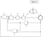
- the example of motor control function comprises a control function Ctl configured to determine a control law.
- the control law defines three references of voltage signals, illustrated as Uabc_ref in the figure, based on the measured current signals I abc in the windings of the electric motor. Each reference of voltage signal is associated to a specific winding of the electric motor 4.
- the control law may be determined to define a speed, a position, and/or a torque of the electric motor 4.
- the control function Ctl can be implemented by the PWM controller PROC or by another controller of the variable speed drive 3.
- the example of motor control function comprises a misbalance estimation function Est mis configured to determine an estimation of the forward I ⁇ ⁇ f and reverse I ⁇ ⁇ r components of the measured current signals in ⁇ frame.
- the forward I ⁇ ⁇ f and reverse I ⁇ ⁇ r components of the measured current signals in ⁇ frame are determined based on the measured current signals I abc and on the current offsets I abc 0 .
- the forward I ⁇ ⁇ f and reverse I ⁇ ⁇ r components of the measured current signals may for example be determined based on equation (4) as explained above.
- the misbalance estimation function Est mis can be implemented by the PWM controller PROC or by another controller of the variable speed drive 3.
- the example of motor control function comprises a PWM function PWMf.
- the amended control law Uabc_cor is inputted in the PWM function PWMs.
- the PWM function PWMf is configured to determine PWM signals PWMs based on the amended control law Uabc_cor.
- the PWM function PWMf is implemented by the PWM controller PROC of the variable speed drive 3.
- the example of motor control function comprises an inverter function INVf.
- the PWM function PWMf is inputted in the inverter function INVf.
- the inverter function INVf is configured to apply three voltages Uabc on the three windings of the electric motor 4 or on the transformer 5 if applicable, based on the PWM signals.
- the inverter function INVF is implemented by the inverter 32 of the variable speed drive 3.
- correction function Cor comprises an alpha-beta transformer function T ⁇ in which the three references Uabc_ref of voltage are inputted.
- the alpha-beta transformer function T ⁇ is configured to transform the three references Uabc_ref of voltage in abc frame in two stationary references of voltage U ⁇ _ref in ⁇ frame by applying a Clarke transformation.
- correction function Cor comprises a misbalance correction function Cor mis in which an estimation of the forward I ⁇ ⁇ f and reverse I ⁇ ⁇ r components of the measured current signals are inputted.
- the misbalance correction function Cor mis is configured to determine a reverse reference voltage U ⁇ _r in ⁇ frame for reducing, preferably canceling, the estimation of the reverse I ⁇ ⁇ r component of the measured current signals when summed to the two stationary references of voltage U ⁇ _ref.
- correction function Cor comprises an inverse alpha-beta transformer function T -1 ⁇ in which the misbalance correction reference in ⁇ frame U ⁇ _cor_mis is inputted.
- the inverse alpha-beta transformer function T -1 ⁇ is configured to determine a misbalance correction reference in abc frame Uabc_cor_mis by transforming the misbalance correction reference from ⁇ frame to abc frame.
- correction function Cor comprises an offset correction function Cor of in which the misbalance correction reference in abc frame Uabc_cor_mis and current offsets I abc 0 of the measured current signals are inputted.
- the offset correction function Cor of is configured to determine an amended control law Uabc_cor for reducing, preferably canceling, the offset currents I abc 0 of the misbalance correction reference in abc frame Uabc_cor_mis.
- the offset correction function Cor of acts on abc frame since the current offsets are directly determined in the abc frame.
- the amended control law Uabc_cor outputted from the offset correction function Cor of therefore at least reduces and preferably cancels the misbalance and offsets of the current between the three windings of the electric motor 4.
- the example method and example of motor control function according to the present disclosure therefore allow at least reducing inductance saturation probability of a specific winding of the electric motor 4, or reducing the torque ripple of the electric motor and the electrical and/or mechanical damages induced by an undesired overheating, and therefore allow reducing the component aging of the electric motor 4.
Landscapes
- Engineering & Computer Science (AREA)
- Power Engineering (AREA)
- Control Of Ac Motors In General (AREA)
Priority Applications (3)
| Application Number | Priority Date | Filing Date | Title |
|---|---|---|---|
| EP22306903.0A EP4387080A1 (fr) | 2022-12-16 | 2022-12-16 | Commande d'entraînement à vitesse variable |
| CN202311642189.XA CN118214338A (zh) | 2022-12-16 | 2023-12-01 | 变速驱动器控制 |
| US18/535,301 US12620923B2 (en) | 2022-12-16 | 2023-12-11 | Variable speed drive control |
Applications Claiming Priority (1)
| Application Number | Priority Date | Filing Date | Title |
|---|---|---|---|
| EP22306903.0A EP4387080A1 (fr) | 2022-12-16 | 2022-12-16 | Commande d'entraînement à vitesse variable |
Publications (1)
| Publication Number | Publication Date |
|---|---|
| EP4387080A1 true EP4387080A1 (fr) | 2024-06-19 |
Family
ID=84887688
Family Applications (1)
| Application Number | Title | Priority Date | Filing Date |
|---|---|---|---|
| EP22306903.0A Pending EP4387080A1 (fr) | 2022-12-16 | 2022-12-16 | Commande d'entraînement à vitesse variable |
Country Status (2)
| Country | Link |
|---|---|
| EP (1) | EP4387080A1 (fr) |
| CN (1) | CN118214338A (fr) |
Citations (3)
| Publication number | Priority date | Publication date | Assignee | Title |
|---|---|---|---|---|
| CN101087125B (zh) * | 2007-06-25 | 2011-05-11 | 中国科学院电工研究所 | 一种具有寿命预测功能的电动汽车电机驱动系统 |
| JP2015023641A (ja) * | 2013-07-18 | 2015-02-02 | 株式会社日立製作所 | 電力変換装置およびエレベーター |
| CN208656661U (zh) * | 2018-08-30 | 2019-03-26 | 珠海格力电器股份有限公司 | 一种逆变电路、变频器、电机、压缩机和空调器 |
-
2022
- 2022-12-16 EP EP22306903.0A patent/EP4387080A1/fr active Pending
-
2023
- 2023-12-01 CN CN202311642189.XA patent/CN118214338A/zh active Pending
Patent Citations (3)
| Publication number | Priority date | Publication date | Assignee | Title |
|---|---|---|---|---|
| CN101087125B (zh) * | 2007-06-25 | 2011-05-11 | 中国科学院电工研究所 | 一种具有寿命预测功能的电动汽车电机驱动系统 |
| JP2015023641A (ja) * | 2013-07-18 | 2015-02-02 | 株式会社日立製作所 | 電力変換装置およびエレベーター |
| CN208656661U (zh) * | 2018-08-30 | 2019-03-26 | 珠海格力电器股份有限公司 | 一种逆变电路、变频器、电机、压缩机和空调器 |
Also Published As
| Publication number | Publication date |
|---|---|
| CN118214338A (zh) | 2024-06-18 |
| US20240204707A1 (en) | 2024-06-20 |
Similar Documents
| Publication | Publication Date | Title |
|---|---|---|
| EP2838193B1 (fr) | Procédé et appareil de commande de la stabilité d'un entraînement de moteur en boucle ouverte | |
| Preindl et al. | Model predictive direct speed control with finite control set of PMSM drive systems | |
| Yu et al. | Optimum DC bus voltage analysis and calculation method for inverters/motors with variable DC bus voltage | |
| US9998058B2 (en) | Control apparatus for AC motor | |
| US9722523B2 (en) | Inverter vector driving system and method for estimating capacitance using the same | |
| US9998052B2 (en) | Rotary electric machine control device | |
| US6605912B1 (en) | Method for controlling a permanent magnet motor | |
| CN101449456B (zh) | 电动机驱动装置以及压缩机驱动装置 | |
| US8164297B2 (en) | Power converter and motor driving system | |
| US9054611B2 (en) | Method and apparatus for stability control of open loop motor drive operation | |
| EP2804310B1 (fr) | Dispositif de commande d'onduleur | |
| US11601080B2 (en) | Motor control device | |
| Kim et al. | Induction motor control with small DC-link capacitor inverter fed by three-phase diode front-end rectifiers | |
| JP3586078B2 (ja) | 電力変換装置 | |
| Lee et al. | Stator-flux-oriented sensorless induction motor drive for optimum low-speed performance | |
| US12095395B2 (en) | Power conversion apparatus | |
| Stando et al. | Novel speed sensorless DTC-SVM scheme for induction motor drives | |
| JP7318727B2 (ja) | 電力変換装置、電力変換方法及びシステム | |
| Yu et al. | Control method for calculating optimum DC bus voltage to improve drive system efficiency in variable DC bus drive systems | |
| EP4387080A1 (fr) | Commande d'entraînement à vitesse variable | |
| US12620923B2 (en) | Variable speed drive control | |
| Usama et al. | Simplified model predicted current control method for speed control of non-silent permanent magnet synchronous motors | |
| US20260005630A1 (en) | Model predictive control for electrical machines with multiple sets of windings | |
| US9000701B2 (en) | Methods, systems and apparatus for generating voltage commands used to control operation of a permanent magnet machine | |
| Green et al. | Inverter AC-drive efficiency |
Legal Events
| Date | Code | Title | Description |
|---|---|---|---|
| PUAI | Public reference made under article 153(3) epc to a published international application that has entered the european phase |
Free format text: ORIGINAL CODE: 0009012 |
|
| STAA | Information on the status of an ep patent application or granted ep patent |
Free format text: STATUS: THE APPLICATION HAS BEEN PUBLISHED |
|
| AK | Designated contracting states |
Kind code of ref document: A1 Designated state(s): AL AT BE BG CH CY CZ DE DK EE ES FI FR GB GR HR HU IE IS IT LI LT LU LV MC ME MK MT NL NO PL PT RO RS SE SI SK SM TR |
|
| STAA | Information on the status of an ep patent application or granted ep patent |
Free format text: STATUS: REQUEST FOR EXAMINATION WAS MADE |
|
| 17P | Request for examination filed |
Effective date: 20241126 |
|
| RBV | Designated contracting states (corrected) |
Designated state(s): AL AT BE BG CH CY CZ DE DK EE ES FI FR GB GR HR HU IE IS IT LI LT LU LV MC ME MK MT NL NO PL PT RO RS SE SI SK SM TR |
|
| GRAP | Despatch of communication of intention to grant a patent |
Free format text: ORIGINAL CODE: EPIDOSNIGR1 |
|
| STAA | Information on the status of an ep patent application or granted ep patent |
Free format text: STATUS: GRANT OF PATENT IS INTENDED |
|
| INTG | Intention to grant announced |
Effective date: 20250410 |
|
| GRAJ | Information related to disapproval of communication of intention to grant by the applicant or resumption of examination proceedings by the epo deleted |
Free format text: ORIGINAL CODE: EPIDOSDIGR1 |
|
| STAA | Information on the status of an ep patent application or granted ep patent |
Free format text: STATUS: REQUEST FOR EXAMINATION WAS MADE |
|
| STAA | Information on the status of an ep patent application or granted ep patent |
Free format text: STATUS: EXAMINATION IS IN PROGRESS |
|
| 17Q | First examination report despatched |
Effective date: 20250704 |
|
| INTC | Intention to grant announced (deleted) | ||
| GRAP | Despatch of communication of intention to grant a patent |
Free format text: ORIGINAL CODE: EPIDOSNIGR1 |
|
| STAA | Information on the status of an ep patent application or granted ep patent |
Free format text: STATUS: GRANT OF PATENT IS INTENDED |
|
| INTG | Intention to grant announced |
Effective date: 20251218 |
|
| GRAS | Grant fee paid |
Free format text: ORIGINAL CODE: EPIDOSNIGR3 |
|
| GRAA | (expected) grant |
Free format text: ORIGINAL CODE: 0009210 |
|
| STAA | Information on the status of an ep patent application or granted ep patent |
Free format text: STATUS: THE PATENT HAS BEEN GRANTED |