EP4387893B1 - Ein system für auftrieb, antrieb und steuerung eines luftfahrzeugs - Google Patents
Ein system für auftrieb, antrieb und steuerung eines luftfahrzeugs Download PDFInfo
- Publication number
- EP4387893B1 EP4387893B1 EP22769570.7A EP22769570A EP4387893B1 EP 4387893 B1 EP4387893 B1 EP 4387893B1 EP 22769570 A EP22769570 A EP 22769570A EP 4387893 B1 EP4387893 B1 EP 4387893B1
- Authority
- EP
- European Patent Office
- Prior art keywords
- airfoil
- flap
- cross
- fan
- flow
- Prior art date
- Legal status (The legal status is an assumption and is not a legal conclusion. Google has not performed a legal analysis and makes no representation as to the accuracy of the status listed.)
- Active
Links
Images


Classifications
-
- B—PERFORMING OPERATIONS; TRANSPORTING
- B64—AIRCRAFT; AVIATION; COSMONAUTICS
- B64C—AEROPLANES; HELICOPTERS
- B64C29/00—Aircraft capable of landing or taking-off vertically, e.g. vertical take-off and landing [VTOL] aircraft
- B64C29/0008—Aircraft capable of landing or taking-off vertically, e.g. vertical take-off and landing [VTOL] aircraft having its flight directional axis horizontal when grounded
- B64C29/0016—Aircraft capable of landing or taking-off vertically, e.g. vertical take-off and landing [VTOL] aircraft having its flight directional axis horizontal when grounded the lift during taking-off being created by free or ducted propellers or by blowers
-
- B—PERFORMING OPERATIONS; TRANSPORTING
- B64—AIRCRAFT; AVIATION; COSMONAUTICS
- B64C—AEROPLANES; HELICOPTERS
- B64C15/00—Attitude, flight direction, or altitude control by jet reaction
- B64C15/14—Attitude, flight direction, or altitude control by jet reaction the jets being other than main propulsion jets
-
- B—PERFORMING OPERATIONS; TRANSPORTING
- B64—AIRCRAFT; AVIATION; COSMONAUTICS
- B64C—AEROPLANES; HELICOPTERS
- B64C11/00—Propellers, e.g. of ducted type; Features common to propellers and rotors for rotorcraft
- B64C11/006—Paddle wheels
-
- B—PERFORMING OPERATIONS; TRANSPORTING
- B64—AIRCRAFT; AVIATION; COSMONAUTICS
- B64C—AEROPLANES; HELICOPTERS
- B64C21/00—Influencing air flow over aircraft surfaces by affecting boundary layer flow
- B64C21/02—Influencing air flow over aircraft surfaces by affecting boundary layer flow by use of slot, ducts, porous areas or the like
- B64C21/04—Influencing air flow over aircraft surfaces by affecting boundary layer flow by use of slot, ducts, porous areas or the like for blowing
-
- B—PERFORMING OPERATIONS; TRANSPORTING
- B64—AIRCRAFT; AVIATION; COSMONAUTICS
- B64C—AEROPLANES; HELICOPTERS
- B64C39/00—Aircraft not otherwise provided for
- B64C39/003—Aircraft not otherwise provided for with wings, paddle wheels, bladed wheels, moving or rotating in relation to the fuselage
- B64C39/005—Aircraft not otherwise provided for with wings, paddle wheels, bladed wheels, moving or rotating in relation to the fuselage about a horizontal transversal axis
-
- B—PERFORMING OPERATIONS; TRANSPORTING
- B64—AIRCRAFT; AVIATION; COSMONAUTICS
- B64C—AEROPLANES; HELICOPTERS
- B64C9/00—Adjustable control surfaces or members, e.g. rudders
- B64C9/04—Adjustable control surfaces or members, e.g. rudders with compound dependent movements
-
- B—PERFORMING OPERATIONS; TRANSPORTING
- B64—AIRCRAFT; AVIATION; COSMONAUTICS
- B64C—AEROPLANES; HELICOPTERS
- B64C23/00—Influencing air flow over aircraft surfaces, not otherwise provided for
- B64C23/02—Influencing air flow over aircraft surfaces, not otherwise provided for by means of rotating members of cylindrical or similar form
-
- Y—GENERAL TAGGING OF NEW TECHNOLOGICAL DEVELOPMENTS; GENERAL TAGGING OF CROSS-SECTIONAL TECHNOLOGIES SPANNING OVER SEVERAL SECTIONS OF THE IPC; TECHNICAL SUBJECTS COVERED BY FORMER USPC CROSS-REFERENCE ART COLLECTIONS [XRACs] AND DIGESTS
- Y02—TECHNOLOGIES OR APPLICATIONS FOR MITIGATION OR ADAPTATION AGAINST CLIMATE CHANGE
- Y02T—CLIMATE CHANGE MITIGATION TECHNOLOGIES RELATED TO TRANSPORTATION
- Y02T50/00—Aeronautics or air transport
- Y02T50/10—Drag reduction
Definitions
- the invention relations to system and method for lift, propulsion, and control of an airborne craft. More specifically, to control the elements of the system to achieve the required lift, propulsion and control of the aircraft during vertical, horizontal and transitional flight operations.
- VTOL Vertical Take-Off and Landing
- STOL Short take-off and Landing
- VTOL and STOL systems today employ a vectored thrust mechanism to provide vertical flight capability. This is achieved by designing the propulsion system in multiple ways. However, these propulsion systems typically require rotating or tilting the entire vehicle and/or engines and/or propellors, thereby necessitating complex structures and mechanisms.
- the cross-flow fan (CFF) or tangential fan, developed in 1893 by Mortier is used extensively in the heating, ventilating and air conditioning (HVAC) industry.
- the fan is usually long relative to the diameter, so the flow approximately remains 2-dimensional (2D) along the length of the fan.
- the CFF uses an impeller with forward curved blades, placed in a housing consisting of a rear wall and vortex wall. Unlike radial machines, the main flow travels transversely across the impeller, passing the blading twice.
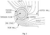
- FIG. 1 illustrates a prior art system that shows a section view of a typical HVAC configuration.
- the propulsor For efficient forward flight of an airborne craft, the propulsor must ingest and expel the flow at a small angle to the forward flight direction.
- the conventional HVAC-type CFF housing characterized by approximately a 90 degree turn from inlet to outlet, is not well suited for this application.
- the popularity of the CFF comes from its ability to handle flow distortion and provide high pressure coefficient. Effectively a rectangular fan, the diameter readily scales to fit the available space, and the length is adjustable to meet flow rate requirements for the particular application. Since the flow both enters and exits the impeller radially, the cross-flow fan is well suited for aircraft applications particularly where a spanwise trailing edge air jet is desirable for distributed propulsion. Due to the 2D nature of the flow the fan readily integrates into an airfoil for use in both thrust production and vectoring and boundary layer control.
- embedded propulsion provides reduced noise and increased safety, since the propulsor is now buried within the structure of the aircraft (e.g. no exposed propellers). Also, by eliminating the engine pylon/nacelle support structure, the aircraft parasitic drag can be reduced by up to 18 to 20%, thus improving cruise efficiency and range.
- the present invention provides a system for lift, propulsion and control for an aircraft vehicle to facilitate Vertical take-off and landing (VTOL)/Short takeoff and landing (STOL) operations as per claim 1.
- VTOL Vertical take-off and landing
- STOL Short takeoff and landing
- the exit duct is further configured to eject a longitudinal jet of air, when in use, required for producing the vertical lift in combination with a predefined fan speed of the cross flow fan and position of the flexlip and the flap.
- the predefined speed may be a suitable speed of the fan to produce the longitudinal jet of air required for the vertical lift of the aircraft.
- the flap and the flexlip are connected and moved through an angle so that the thrust can be vectored through an angle of more than 70 degrees.
- the present invention provides the exit duct as described wherein the flap and flexlip are connected and actuated or moved through an angle so that the thrust can be vectored through an angle of more than 70 degrees.
- the present invention provides the exit duct as described wherein a change in the actuated angles of the flap and lip produce a change in the magnitude and/or direction of said thrust the change being used to control the attitude of the aircraft.
- the present invention provides the exit duct as described wherein the inner edge of the upper face of the flap consequentially rotates to increase the inlet flow area to the rotor such that, when combined with increased rotor speed, increased mass flow is available from the fan when the flap is rotated to the position to produce vertical thrust for VTOL operation.
- the present invention provides an airfoil, embedded cross-flow fan and exit duct element with distributed flow that has low parasitic drag in forward flight.
- the present invention provides an airfoil, embedded cross-flow fan and exit duct element with distributed flow wherein the airfoil has a thickness to chord ratio greater than 30% and any flow separation is limited by boundary layer ingestion into the crossflow fan.
- the present invention provides an airfoil, embedded cross-flow fan and exit duct element wherein the rotor speed of the cross-flow fan is independent of any other fans on the craft and the speed is varied relative to the other fans to assist in controlling the attitude and flight direction of the aircraft.
- the present invention provides an airfoil, embedded cross-flow fan and exit duct element wherein the crossflow fan has a rotor diameter between 10% to 30% and more specifically in the ranges of 15% to 25% of the chord of the airfoil.
- the present invention provides an airfoil, embedded cross-flow fan and exit duct element wherein the airfoil has an upper surface radius that is between the ranges of 50% to 60%.
- the range may be configured to be 55 and 58% of chord and extending over more than one third of the upper surface, a lower surface that is substantially flat and extends over more than one third of the lower surface and a rear surface that forms the rear wall of the embedded crossflow fan.
- the present invention provides an airfoil, embedded cross-flow fan and exit duct element that facilitates parasitic drag in forward flight that decreases with increasing angle of attack up to a maximum of between 5 and 15 degrees.
- the angle of attack may be varied outside the ranges of 5 to 15 degrees.
- the present invention provides an airfoil, embedded cross-flow fan and exit duct element wherein the cross-flow fan ingests the boundary layer the airfoil and thereby facilitates stall free operation at angles of attack between 5 and 20 degrees.
- the angle of attack may be varied outside the ranges of 5 to 20 degrees.
- the present invention provides an airfoil, embedded cross-flow fan and exit duct element wherein the exit duct can be configured to deflect the jet from the trailing edge of the element through an angle of between 50 and 90 degrees from the jet direction for optimal forward flight.
- FIG. 1 is illustrating a prior art cross-flow fan.
- the CFF is provided with an inlet and an outlet, padding region, a rear wall and vortex wall. A first stage and a second stage to manage the through flow through the CFF.
- fig. 1 shows a sectional view of a Heating, Ventilating and Air Conditioning (HVAC) configuration of the cross-flow fan.
- HVAC Heating, Ventilating and Air Conditioning
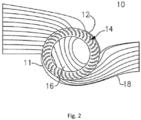
- FIG. 2 is an illustration of a baseline inline housing according to an embodiment of the present invention.
- the crossflow fan (CFF) assembly 10 consisting of a rotor 14, a rear wall 11 and a vortex wall 12. The through flow achieved is illustrated by 16.
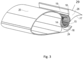
- FIG: 3 illustrates a diagram of a lift, propulsion and control system showing the exit duct geometry of the flap and flexlip when configured for forward flight.
- fig 3 there is seen an airfoil 20, a flexlip 24 attached to and forming part of airfoil 20, a crossflow fan rotor 14, a flap 26 rotatable and mounted about the axis of the rotor 14 and an exit duct 15 from the crossflow fan rotor 14 and formed by the lower face 17 of flap 26 and the upper face 16 of flexlip 24.
- the position of the flexlip 24 and flap 26 are as shown in fig 3 .
- a longitudinal jet of air from duct 15 is ejected from the length of the lift, propulsion and control system to achieve distributed propulsion, and desirably the forward flight propulsive efficiency benefits.
- the edge 18 of face 19 of the flap 26 restricts the inlet area to the crossflow fan to provide an optimal flow rate through the fan for best propulsive efficiency.
- FIG. 4 is an illustration of a lift, propulsion and control system showing the exit duct geometry of the flap and flexlip when configured for VTOL operation.
- the flexlip 24 and the flap 26 are moved to different position as compared to fig 3 .
- Shown is an airfoil 20, a flexlip 24 attached to and forming part of airfoil 20, a crossflow fan rotor 14, a flap 26 rotatable and mounted about the axis of rotor 14 and an exit duct 15 from the crossflow fan rotor 14 and formed by the lower face 17 of flap 26 and the upper face 16 of flexlip 24.
- the flexlip 24 and flap 26 configured in this position, ie.
- a longitudinal jet of air from duct 15 is ejected from the length of the lift, propulsion and control system to achieve a substantially vertical jet thereby producing upward thrust or vertical lift for VTOL operation.
- the edge 18 of face 19 moves to create a much larger inlet area to the crossflow fan thereby providing an optimal flow rate through the fan for vertical thrust.
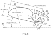
- FIG. 5 illustrates a cross section of an airfoil, embedded crossflow fan and exit duct geometry according to the present invention showing the range of movement of the flap and flexlip.
- the angle 28 can be configured to be different from the angle 25.
- the angle of attack 22 is set achieve a maximum lift to drag ratio in conjunction with the exit angle of the duct jet.
- the area ratio of the fan inlet area to fan exit area may be configured to be optimized by the movement of flap 26 for both high propulsive efficiency in the upper position and high vertical thrust in the lower position.
- the present invention is competitive with conventional propulsion technologies.
- the raised inlet formed by flap 26 eliminates the fan size restriction created if the fan is fully embedded within the airfoil 20.
- cross-flow fan performance is quite insensitive to even large amounts of wake ingestion, making it ideal for this type of configuration.
- the fan of the present invention is capable of drawing in the boundary layer, regardless of its thickness.
- the wake can be quite large, producing large pressure drag. This renders very thick wing sections impractical for most aircraft applications as the drag penalty outweighs any benefits gained in lift or interior volume.
- the flow With-out the suction effect of a rear-mounted crossflow fan rotor 14, the flow separates even at only a small angle of attack.
- the embedded cross-flow fan near the trailing edge eliminate flow separation by drawing the flow back toward the surface and into the fan ducting, yielding very high lift coefficients.
- the distributed propulsion generated by the long spanwise jet of air from duct 15 gives rise to the phenomenon known as distributed propulsion which can be used to generate a very high propulsive efficiency in forward flight. This, together with the lower drag resulting from the absence of engine nacelle, pylon, and interference drag offsets any low fan efficiency.
- a more ideal Lift, Propulsion and Control Element for a VTOL aircraft with a crossflow fan would desirably vector the flow from a substantially horizontal direction to a substantially vertical direction but would also provide for efficient increased thrust during VTOL because the thrust required for VTOL operation is significantly more than that required for forward propulsion.
- This additional thrust can be achieved by increasing rotor speed, but this decrease lifting efficiency or power loading. To offset this loss of efficiency fan area is increased.
- a flexing or morphing lip coordinates with a flap to provide both a desirable exit flow vector for forward flight propulsive efficiency and a desirable area ratio across the fan, the flap and lip then moved to a second position provide sufficient change in the area ratio across the fan and redirection of the exit flow vector to provide effective VTOL operation.
- the effective VTOL operation allows the wing element and attached fuselage and passengers to remain substantially horizontal during take-off, landing and transition to cruise flight.
- FIG. 6 is a diagram illustrating the flow around and through the wing and crossflow fan element when configured for VTOL, according to the present invention. The variation in the position of the flap and the flexlip can be observed to achieve the required VTOL.
- FIG. 7 is a diagram illustrating the flow around and through the wing and crossflow fan element when configured for horizontal forward flight, according to the present invention.
- the variation in the position of the flap and flexlip for horizontal forward flight to achieve the required thrust is observed in fig 7 are different from the previous fig 6 .
- the system of the present invention achieves two configurations with the variations in the positions of the flap and the flexlip and thus varies the air duct and helps to achieve the required thrust for both forward flight motions and vertical take-off and landing of the aircraft.
Landscapes
- Engineering & Computer Science (AREA)
- Aviation & Aerospace Engineering (AREA)
- Chemical & Material Sciences (AREA)
- Combustion & Propulsion (AREA)
- Structures Of Non-Positive Displacement Pumps (AREA)
Claims (9)
- Ein System zum Bereitstellen von Auftrieb, Antrieb und Steuerung für Senkrechtstart- und - landung (VTOL)/Kurzstart- und -landung (STOL)-Operationen eines Luftfahrzeugs, wobei das System umfasst:a. mindestens einen Tragflügel (20), der sich von einer Vorderkante zu einer Hinterkante erstreckt;b. einen Querströmungslüfterrotor (14) mit einer Rotationsachse, der zumindest teilweise im Tragflügel (20) eingebettet ist, im Wesentlichen die gleiche Länge wie der Tragflügel aufweist und angrenzend an die Hinterkante des Tragflügels montiert ist; undc. einen Austrittskanal (15) für den Querströmungslüfter, der so konfiguriert ist, dass er einen verteilten Strömungsausstoß entlang der Hinterkante des Tragflügels bereitstellt und so ausgelegt ist, dass er einen gerichteten Schub erzeugt; und wobei das System weiterhin umfasst:d. eine Klappe (26), die drehbar um die Rotationsachse (27) des Querströmungslüfters angeordnet ist, wobei die Klappe eine obere Fläche (29) und eine untere Fläche (17) aufweist,dadurch gekennzeichnet, dassder Tragflügel (20) eine Flexlippe (24) mit einer oberen Fläche (16) umfasst,wobei die untere Fläche (17) der Klappe und die obere Fläche (16) der Flexlippe (24) den Austrittskanal (15) bilden; wobei die Klappe (26) und die Flexlippe (24), die den Austrittskanal (15) bilden, weiterhin so konfiguriert sind, dass sie sich gleichzeitig, jedoch mit unterschiedlichen Winkelgeschwindigkeiten bewegen, um eine gewünschte Änderung sowohl des Winkels als auch des Massenstroms des gerichteten Schubs bereitzustellen.
- Das System gemäß Anspruch 1, wobei der Austrittskanal (15) weiterhin so konfiguriert ist, dass er im Einsatz am Luftfahrzeug einen längsgerichteten Luftstrahl ausstößt, der erforderlich ist, um den vertikalen Auftrieb in Kombination mit einer vorgegebenen Lüfterdrehzahl des Querströmungslüfters (14) sowie der Position der Flexlippe (24) und der Klappe (26) zu erzeugen.
- Das System gemäß Anspruch 1, wobei die Klappe (26) und die Flexlippe (24) so konfiguriert sind, dass sie über einen Winkel bewegt werden können, um einen Schub zu erzeugen, der durch einen Winkel gerichtet werden kann, sodass eine Änderung sowohl der Größe als auch der Richtung des Schubs erzeugt wird.
- Das System gemäß Anspruch 1, wobei die Klappe (26) und die Flexlippe (24) verbunden sind und über einen Winkel bewegt werden, sodass der Schub durch einen Winkel von mehr als 70 Grad gerichtet werden kann.
- Das System gemäß Anspruch 1, wobei der Tragflügel (20) ein Dicken-zu-Sehnen-Verhältnis aufweist, das größer als 30% ist, und die Strömungsablösung durch die Grenzschichteinleitung in den Querströmungslüfter begrenzt wird.
- Das System gemäß Anspruch 1, wobei der Tragflügel (20) gekrümmt ist, mit einem oberen Flächenradius zwischen 50% und 60% der Flügelsehne, wobei sich die Krümmung über mindestens ein Drittel der oberen Fläche erstreckt, eine im Wesentlichen flache untere Fläche aufweist, die sich über mindestens ein Drittel der unteren Fläche erstreckt, und eine hintere Fläche aufweist, die die Rückwand des eingebetteten Querströmungslüfters bildet.
- Das System gemäß Anspruch 1, wobei der Querströmungslüfter (14) mit einem Rotordurchmesser zwischen 10% und 30% der Sehne des Tragflügels (20) konfiguriert ist.
- Das System gemäß Anspruch 1, wobei das System weiterhin so konfiguriert ist, dass es eine verteilte Strömung entlang des Querströmungslüfters bereitstellt, die im Vorwärtsflug einen geringen parasitären Widerstand aufweist, wobei der Widerstand mit zunehmendem Anstellwinkel (22) bis zu einem Maximum zwischen 5 und 15 Grad abnimmt.
- Das System gemäß Anspruch 1, wobei der Querströmungslüfter (14) so konfiguriert ist, dass er die Grenzschicht des Tragflügels ansaugt, um einen strömungsabrissfreien Betrieb bei Anstellwinkeln (22) zwischen 5 und 20 Grad zu ermöglichen.
Applications Claiming Priority (2)
| Application Number | Priority Date | Filing Date | Title |
|---|---|---|---|
| AU2021902564A AU2021902564A0 (en) | 2021-08-17 | Airfoil, crossflow fan and duct element for lift, propulsion and control. | |
| PCT/EP2022/072973 WO2023021095A1 (en) | 2021-08-17 | 2022-08-17 | A system for lift, propulsion and control of an airborne craft |
Publications (3)
| Publication Number | Publication Date |
|---|---|
| EP4387893A1 EP4387893A1 (de) | 2024-06-26 |
| EP4387893B1 true EP4387893B1 (de) | 2025-05-07 |
| EP4387893C0 EP4387893C0 (de) | 2025-05-07 |
Family
ID=83318908
Family Applications (1)
| Application Number | Title | Priority Date | Filing Date |
|---|---|---|---|
| EP22769570.7A Active EP4387893B1 (de) | 2021-08-17 | 2022-08-17 | Ein system für auftrieb, antrieb und steuerung eines luftfahrzeugs |
Country Status (4)
| Country | Link |
|---|---|
| US (1) | US12509219B2 (de) |
| EP (1) | EP4387893B1 (de) |
| CN (1) | CN117836207A (de) |
| WO (1) | WO2023021095A1 (de) |
Citations (1)
| Publication number | Priority date | Publication date | Assignee | Title |
|---|---|---|---|---|
| RO134042A2 (ro) * | 2018-10-19 | 2020-04-30 | Liviu Grigorian Giurca | Sistem de propulsie şi aeronave |
Family Cites Families (17)
| Publication number | Priority date | Publication date | Assignee | Title |
|---|---|---|---|---|
| US3178131A (en) | 1963-10-03 | 1965-04-13 | Laing Nikolaus | Aircraft wing structure |
| US7641144B2 (en) | 2005-04-21 | 2010-01-05 | Syracuse University | Cross-flow fan propulsion system |
| JP2010504249A (ja) * | 2006-09-25 | 2010-02-12 | アギラール,ミシェル | 回転翼を有しない垂直離着陸機 |
| EP2285674A4 (de) * | 2008-05-23 | 2013-12-18 | David Birkenstock | System für grenzschichtsteuerung und entsprechende verfahren |
| DE102009057340A1 (de) * | 2009-12-07 | 2011-06-09 | Airbus Operations Gmbh | Hochauftriebssystem für ein Flugzeug, Verfahren zum Bewegen einer Auftriebsklappe und Flugzeug mit einem Hochauftriebssystem |
| US20120111994A1 (en) | 2010-01-15 | 2012-05-10 | Propulsive Wing, LLC | Cross-flow fan propulsion system |
| ITRM20100476A1 (it) * | 2010-09-13 | 2012-03-14 | Giacalone Stefania | Turbina fan tangenziale ad alto rendimento per aeronautica |
| SE541609C2 (sv) | 2013-06-25 | 2019-11-12 | Foersvarets Materielverk | Framdrivningssystem för flygfarkost |
| US9783291B2 (en) | 2014-04-18 | 2017-10-10 | Propulsive Wing, LLC | Hybrid axial/cross-flow fan multi-rotor aerial vehicle |
| US10633090B2 (en) * | 2016-03-17 | 2020-04-28 | United Technologies Corporation | Cross flow fan with exit guide vanes |
| CN105882942B (zh) * | 2016-05-27 | 2018-11-09 | 南京航空航天大学 | 一种高效低速飞行器 |
| US10377480B2 (en) * | 2016-08-10 | 2019-08-13 | Bell Helicopter Textron Inc. | Apparatus and method for directing thrust from tilting cross-flow fan wings on an aircraft |
| US10421541B2 (en) * | 2016-08-10 | 2019-09-24 | Bell Helicopter Textron Inc. | Aircraft with tilting cross-flow fan wings |
| CN107140208A (zh) * | 2017-04-11 | 2017-09-08 | 中国民航大学 | 短距起降高载荷多轴扇翼无人机 |
| JP7346165B2 (ja) * | 2019-08-29 | 2023-09-19 | 三菱重工業株式会社 | クロスフローファン、これを備えた揚力発生装置およびこれを備えた航空機 |
| CN110834714B (zh) * | 2019-10-16 | 2024-08-06 | 中国航天空气动力技术研究院 | 一种轻质柔性可变后缘弯度机翼 |
| DE102019131673A1 (de) * | 2019-11-22 | 2021-05-27 | Timo Schnoelzer | Beförderungsmittel für einen Flugbetrieb sowie Verfahren zum Befördern einer Last |
-
2022
- 2022-08-17 EP EP22769570.7A patent/EP4387893B1/de active Active
- 2022-08-17 CN CN202280056001.0A patent/CN117836207A/zh active Pending
- 2022-08-17 US US18/681,875 patent/US12509219B2/en active Active
- 2022-08-17 WO PCT/EP2022/072973 patent/WO2023021095A1/en not_active Ceased
Patent Citations (1)
| Publication number | Priority date | Publication date | Assignee | Title |
|---|---|---|---|---|
| RO134042A2 (ro) * | 2018-10-19 | 2020-04-30 | Liviu Grigorian Giurca | Sistem de propulsie şi aeronave |
Also Published As
| Publication number | Publication date |
|---|---|
| CN117836207A (zh) | 2024-04-05 |
| US20240336350A1 (en) | 2024-10-10 |
| US12509219B2 (en) | 2025-12-30 |
| WO2023021095A1 (en) | 2023-02-23 |
| EP4387893A1 (de) | 2024-06-26 |
| EP4387893C0 (de) | 2025-05-07 |
Similar Documents
| Publication | Publication Date | Title |
|---|---|---|
| US7665689B2 (en) | Unconventional integrated propulsion systems and methods for blended wing body aircraft | |
| US8448905B2 (en) | Aircraft with aerodynamic lift generating device | |
| KR102586347B1 (ko) | 유체 추진 시스템 | |
| EP2084061B1 (de) | Ultraschallflugzeugmotor | |
| US8636241B2 (en) | Hybrid jet/electric VTOL aircraft | |
| CN118974381A (zh) | 航空推进器 | |
| EP3016859B1 (de) | Antriebssystem für eine flugvorrichtung | |
| CN114954899A (zh) | 用于飞行器的机翼组件 | |
| US20220258858A1 (en) | Rotary wing aircraft with a shrouded tail propeller | |
| US12202604B2 (en) | Vertical take off and landing aircraft with fluidic propulsion system | |
| US12545400B2 (en) | Parallel and series multi-stage electric fan | |
| EP4387893B1 (de) | Ein system für auftrieb, antrieb und steuerung eines luftfahrzeugs | |
| WO2024086324A1 (en) | Aircraft with ducted propulsion | |
| WO2021242463A2 (en) | Vertical take off and landing aircraft with fluidic propulsion system | |
| JP7217272B2 (ja) | ウィングレットエジェクタ構成 | |
| EP4387891B1 (de) | Lagesteuerungssystem für ein mehrrotoriges evtol-flugzeug mit querstromgebläse |
Legal Events
| Date | Code | Title | Description |
|---|---|---|---|
| STAA | Information on the status of an ep patent application or granted ep patent |
Free format text: STATUS: UNKNOWN |
|
| STAA | Information on the status of an ep patent application or granted ep patent |
Free format text: STATUS: THE INTERNATIONAL PUBLICATION HAS BEEN MADE |
|
| PUAI | Public reference made under article 153(3) epc to a published international application that has entered the european phase |
Free format text: ORIGINAL CODE: 0009012 |
|
| STAA | Information on the status of an ep patent application or granted ep patent |
Free format text: STATUS: REQUEST FOR EXAMINATION WAS MADE |
|
| 17P | Request for examination filed |
Effective date: 20240308 |
|
| AK | Designated contracting states |
Kind code of ref document: A1 Designated state(s): AL AT BE BG CH CY CZ DE DK EE ES FI FR GB GR HR HU IE IS IT LI LT LU LV MC MK MT NL NO PL PT RO RS SE SI SK SM TR |
|
| DAV | Request for validation of the european patent (deleted) | ||
| DAX | Request for extension of the european patent (deleted) | ||
| GRAP | Despatch of communication of intention to grant a patent |
Free format text: ORIGINAL CODE: EPIDOSNIGR1 |
|
| STAA | Information on the status of an ep patent application or granted ep patent |
Free format text: STATUS: GRANT OF PATENT IS INTENDED |
|
| INTG | Intention to grant announced |
Effective date: 20241219 |
|
| GRAS | Grant fee paid |
Free format text: ORIGINAL CODE: EPIDOSNIGR3 |
|
| GRAA | (expected) grant |
Free format text: ORIGINAL CODE: 0009210 |
|
| STAA | Information on the status of an ep patent application or granted ep patent |
Free format text: STATUS: THE PATENT HAS BEEN GRANTED |
|
| AK | Designated contracting states |
Kind code of ref document: B1 Designated state(s): AL AT BE BG CH CY CZ DE DK EE ES FI FR GB GR HR HU IE IS IT LI LT LU LV MC MK MT NL NO PL PT RO RS SE SI SK SM TR |
|
| REG | Reference to a national code |
Ref country code: GB Ref legal event code: FG4D |
|
| REG | Reference to a national code |
Ref country code: CH Ref legal event code: EP |
|
| REG | Reference to a national code |
Ref country code: DE Ref legal event code: R096 Ref document number: 602022014421 Country of ref document: DE |
|
| REG | Reference to a national code |
Ref country code: IE Ref legal event code: FG4D |
|
| U01 | Request for unitary effect filed |
Effective date: 20250605 |
|
| U07 | Unitary effect registered |
Designated state(s): AT BE BG DE DK EE FI FR IT LT LU LV MT NL PT RO SE SI Effective date: 20250613 |
|
| U20 | Renewal fee for the european patent with unitary effect paid |
Year of fee payment: 4 Effective date: 20250821 |
|
| PG25 | Lapsed in a contracting state [announced via postgrant information from national office to epo] |
Ref country code: ES Free format text: LAPSE BECAUSE OF FAILURE TO SUBMIT A TRANSLATION OF THE DESCRIPTION OR TO PAY THE FEE WITHIN THE PRESCRIBED TIME-LIMIT Effective date: 20250507 |
|
| PG25 | Lapsed in a contracting state [announced via postgrant information from national office to epo] |
Ref country code: GR Free format text: LAPSE BECAUSE OF FAILURE TO SUBMIT A TRANSLATION OF THE DESCRIPTION OR TO PAY THE FEE WITHIN THE PRESCRIBED TIME-LIMIT Effective date: 20250808 |
|
| PGFP | Annual fee paid to national office [announced via postgrant information from national office to epo] |
Ref country code: NO Payment date: 20250820 Year of fee payment: 4 |
|
| PG25 | Lapsed in a contracting state [announced via postgrant information from national office to epo] |
Ref country code: PL Free format text: LAPSE BECAUSE OF FAILURE TO SUBMIT A TRANSLATION OF THE DESCRIPTION OR TO PAY THE FEE WITHIN THE PRESCRIBED TIME-LIMIT Effective date: 20250507 |
|
| PG25 | Lapsed in a contracting state [announced via postgrant information from national office to epo] |
Ref country code: HR Free format text: LAPSE BECAUSE OF FAILURE TO SUBMIT A TRANSLATION OF THE DESCRIPTION OR TO PAY THE FEE WITHIN THE PRESCRIBED TIME-LIMIT Effective date: 20250507 |
|
| PG25 | Lapsed in a contracting state [announced via postgrant information from national office to epo] |
Ref country code: RS Free format text: LAPSE BECAUSE OF FAILURE TO SUBMIT A TRANSLATION OF THE DESCRIPTION OR TO PAY THE FEE WITHIN THE PRESCRIBED TIME-LIMIT Effective date: 20250807 |
|
| PG25 | Lapsed in a contracting state [announced via postgrant information from national office to epo] |
Ref country code: IS Free format text: LAPSE BECAUSE OF FAILURE TO SUBMIT A TRANSLATION OF THE DESCRIPTION OR TO PAY THE FEE WITHIN THE PRESCRIBED TIME-LIMIT Effective date: 20250907 |
|
| PG25 | Lapsed in a contracting state [announced via postgrant information from national office to epo] |
Ref country code: SM Free format text: LAPSE BECAUSE OF FAILURE TO SUBMIT A TRANSLATION OF THE DESCRIPTION OR TO PAY THE FEE WITHIN THE PRESCRIBED TIME-LIMIT Effective date: 20250507 |
|
| PG25 | Lapsed in a contracting state [announced via postgrant information from national office to epo] |
Ref country code: CZ Free format text: LAPSE BECAUSE OF FAILURE TO SUBMIT A TRANSLATION OF THE DESCRIPTION OR TO PAY THE FEE WITHIN THE PRESCRIBED TIME-LIMIT Effective date: 20250507 |
|
| PG25 | Lapsed in a contracting state [announced via postgrant information from national office to epo] |
Ref country code: SK Free format text: LAPSE BECAUSE OF FAILURE TO SUBMIT A TRANSLATION OF THE DESCRIPTION OR TO PAY THE FEE WITHIN THE PRESCRIBED TIME-LIMIT Effective date: 20250507 |
|
| PLBE | No opposition filed within time limit |
Free format text: ORIGINAL CODE: 0009261 |
|
| STAA | Information on the status of an ep patent application or granted ep patent |
Free format text: STATUS: NO OPPOSITION FILED WITHIN TIME LIMIT |
|
| REG | Reference to a national code |
Ref country code: CH Ref legal event code: L10 Free format text: ST27 STATUS EVENT CODE: U-0-0-L10-L00 (AS PROVIDED BY THE NATIONAL OFFICE) Effective date: 20260318 |
|
| REG | Reference to a national code |
Ref country code: CH Ref legal event code: H13 Free format text: ST27 STATUS EVENT CODE: U-0-0-H10-H13 (AS PROVIDED BY THE NATIONAL OFFICE) Effective date: 20260324 |
|
| PG25 | Lapsed in a contracting state [announced via postgrant information from national office to epo] |
Ref country code: MC Free format text: LAPSE BECAUSE OF FAILURE TO SUBMIT A TRANSLATION OF THE DESCRIPTION OR TO PAY THE FEE WITHIN THE PRESCRIBED TIME-LIMIT Effective date: 20250507 |
|
| 26N | No opposition filed |
Effective date: 20260210 |
|
| PG25 | Lapsed in a contracting state [announced via postgrant information from national office to epo] |
Ref country code: CH Free format text: LAPSE BECAUSE OF NON-PAYMENT OF DUE FEES Effective date: 20250831 |