EP4387904B1 - Capsule monodose pour la préparation d'infusions ou de boissons solubles - Google Patents
Capsule monodose pour la préparation d'infusions ou de boissons solubles Download PDFInfo
- Publication number
- EP4387904B1 EP4387904B1 EP22754163.8A EP22754163A EP4387904B1 EP 4387904 B1 EP4387904 B1 EP 4387904B1 EP 22754163 A EP22754163 A EP 22754163A EP 4387904 B1 EP4387904 B1 EP 4387904B1
- Authority
- EP
- European Patent Office
- Prior art keywords
- aluminum
- dose capsule
- capsule
- seal
- collar
- Prior art date
- Legal status (The legal status is an assumption and is not a legal conclusion. Google has not performed a legal analysis and makes no representation as to the accuracy of the status listed.)
- Active
Links
Images



Classifications
-
- B—PERFORMING OPERATIONS; TRANSPORTING
- B65—CONVEYING; PACKING; STORING; HANDLING THIN OR FILAMENTARY MATERIAL
- B65D—CONTAINERS FOR STORAGE OR TRANSPORT OF ARTICLES OR MATERIALS, e.g. BAGS, BARRELS, BOTTLES, BOXES, CANS, CARTONS, CRATES, DRUMS, JARS, TANKS, HOPPERS, FORWARDING CONTAINERS; ACCESSORIES, CLOSURES, OR FITTINGS THEREFOR; PACKAGING ELEMENTS; PACKAGES
- B65D85/00—Containers, packaging elements or packages, specially adapted for particular articles or materials
- B65D85/70—Containers, packaging elements or packages, specially adapted for particular articles or materials for materials not otherwise provided for
- B65D85/804—Disposable containers or packages with contents which are mixed, infused or dissolved in situ, i.e. without having been previously removed from the package
- B65D85/8043—Packages adapted to allow liquid to pass through the contents
- B65D85/8064—Sealing means for the interface with the processing machine
Definitions
- a single-dose aluminum capsule for preparing infusion or soluble beverages in an extraction device comprising an edge provided with an improved sealing profile.
- the beverage capsule can be for espresso coffee machines, in particular for preparing highpressure espresso coffee.
- espresso coffee machines generally have an infusion chamber comprising an inlet side of the pressurized water and a side from which the infused/extracted beverage escapes during the passage of water through the capsule.
- Perforation means are present on the water inlet side suitable for perforating the bottom of the capsule thus allowing pressurized water to enter the capsule in order to extract the beverage.
- Such beverage then escapes from the upper part of the capsule at the cover which, subjected to the internal pressure of the water, opens and thus allows the extracted beverage to pass through, which is collected in a dedicated external container.
- the edge of said upper part of the capsule rests on the side opposite the water inlet side and, by virtue of its profile, seals against the side of the infusion chamber from which the beverage escapes.
- the infusion chamber closes correctly and seals even under pressure so that there are no significant leaks of hot water outside the infusion chamber itself.
- the aluminum capsules of the known type therefore comprise a cup provided with a circular perimetral edge suitable for making a seal engagement with a relative abutment edge of the infusion chamber, in such a way as to guarantee the sealing of the water under pressure and make the infusion operation more efficient by forcing the water to pass inside the capsule so as to maximize the effectiveness of the extraction of the beverage.
- aluminum has the considerable advantage of being impermeable to oxygen and water, which means that the coffee in the capsules has a long shelf life, it easily deforms during the filling and packaging step, and is therefore difficult and expensive to implement a reliable seal on the edge of the cup.
- conventional espresso coffee machines comprise a heating element suitable for heating the water up to about 95-98 °C, which is then pumped at high pressure (generally with appropriate pumps) into the infusion chamber, obtaining a reliable seal, which avoids significant leaks and forces pressurized water to pass inside the capsule, is one of the most felt problems in the specific sector.
- capsules are disclosed in WO 2020/053075 A1 and WO 2016/186496 A1 .
- the object of the present invention is to provide a capsule which overcomes the aforementioned drawbacks and therefore guarantees reliable operation.
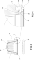
- Figure 3 shows an aluminum capsule 10 according to the invention inserted in an infusion chamber 3 (shown only partially) of an extraction device for preparing beverages.
- Figure 1 instead shows only the aluminum capsule 10, of the single-dose type for preparing a beverage, for example coffee, infusion, soluble, decoction or the like.
- the capsule 10 comprises a hollow body called cup 1 defining therein a compartment for containing at least one substance to be infused or dissolved or extracted by means of a liquid under pressure, such as for example coffee or tea, typically in granular or powder form.
- a liquid under pressure such as for example coffee or tea
- the cup 1 comprises an annular side wall 2 extending in height along a central axis X, between a bottom wall 4 and an opposite front end 6 defining an opening 5. Such opening 5 is covered by a cover 8, perforable or yielding, which closes the capsule 1.
- the side wall 2 has an overall substantially truncated cone shape on the outside, for example realized by the succession of truncated cone surfaces having different angular openings.
- the bottom wall 4 is intended to be crossed by the liquid injected by the extraction device for preparing the beverage, typically hot water or other food liquid, such as milk.
- the bottom 4 provides a perforable central portion 41 by specific perforation means of the extraction machine when the capsule is in use, so as to realize passages for the liquid towards the inside of the cup 1.
- the perforable central portion 41 is provided with a reinforcement edge 42 suitable for providing stiffness to the bottom 4 of the cup 1, avoiding the deformation thereof during the perforation step for the injection of the liquid under pressure.
- the reinforcement edge 42 is an inward fold made in the wall of the cup 1.
- the reinforcement edge 42 defines a wavy shape, visible in Figure 8 .
- the cup 1 comprises a collar 7, typically arranged at the free end of the side wall 2, projecting radially externally.
- the collar 7 has a front face 7b facing towards the opening 5 of the cup 1, and an opposite rear face 7a.
- the front face 7b of the collar 7 is intended for union with the peripheral annular region of the cover 8 which closes the cup 1 at the front end 6.
- the rear face 7a of the collar 7, on the other hand, is intended to engage with an abutment edge 31 of the infusion chamber 3 of the extraction device.
- the extraction device comprises an infusion chamber 3 suitable for housing at least part of the cup 1 of the capsule 10 therein.
- the infusion chamber 3 is movable with respect to a receiving plate 38 between an open position, which allows the capsule 10 to be inserted and removed, and a closed position.
- the infusion chamber 3 When the infusion chamber 3 is in the closed position, as shown in Figure 7 , it forms a closed chamber around the capsule 10 when the heated and pressurized water is fed into the cup 1 (through the bottom 4) to carry out the beverage infusion and extraction step.
- the receiving plate 38 is provided with at least one opening (not shown), to allow the beverage to flow into the final container, for example a cup.
- the infusion chamber 3 is provided with a compression edge 31 having an external portion 31a facing the rear face 7a of the collar 7 of the capsule 10.
- the compression edge 31 is of the double crown type and comprises two circular crowns (which define an internal edge 32 and an external edge 33) connected by an annular recess 34. It should be noted that only the inner edge 32 is used to perform, abutting against the rear face 7a of the collar 7 of the capsule 10, the sealing of the infusion chamber.
- the external edge 33 is shorter than the internal edge 32 and does not compress the collar 7 of the capsule or part of it.
- the rear face 7a of the collar 7 is therefore intended to engage with the internal edge 32 of the infusion chamber 3 of the extraction device to seal the infusion chamber.
- the collar 7 is provided with a particular geometry in such a way as to act itself as a sealing ring of the capsule 10.
- the collar 7 is in fact intended to sealingly engage, at least partially, with the internal edge 32 of the infusion chamber 3 of the extraction device and provides, with the internal edge 32, a head seal.
- the collar 7 of the cup 1 due to features of the material and structural and dimensional features, is at least partially deformable under the action of compression of the internal edge 32 of the machine, so as to provide the seal; the deformation is of a plastic type.
- the collar 7 comprises an end 72, for example a hollow edge obtained by folding back on itself of the terminal portion of the cup 1.
- the terminal portion of the cup 1 forms a curl end 72.
- Such end 72 allows the capsule to be kept in position by virtue of the side arms of the infusion chamber (as seen in Figure 4 ) until the end of the extraction.
- the collar 7 comprises a flat horizontal portion 71, on whose front face 7b is attached the cover 8 which closes the cup 1 at the front end 6.
- the flat portion 41 extends for about 1 mm.
- the flat portion 71 is wide to facilitate the welding step of the cover 8.
- the collar 7 comprises a seal step 91 intended to sealingly engage with the internal edge 32 of the infusion chamber 3 of the extraction device.
- the seal step 91 is defined by a tilted raised portion 911 (i.e. defined by a truncated cone annular wall) preferably at an angle between 2° and 6°, preferably of 4°, with respect to the central axis X.
- the raised portion 911 extends for about 1 mm.
- the seal step 91 is also defined by an abutment portion 912 tilted at an angle between 4° and 12°, preferably of 8°, with respect to the horizontal plane.
- the abutment portion 912 extends for about 1 mm.
- the seal step 91 is engaged by the internal edge 32 during the closing step of the infusion chamber 3.
- the internal edge 32 compresses the seal step 91 as shown by way of example in Figure 7 until it deforms, creating a crease 913 which is inserted at least partially into the annular recess 34 (i.e. between the internal edge 32 and the external edge 33) realizing a seal engagement with the compression edge 31 of the extraction device during the closing step of the infusion chamber.
- the geometry of the seal step 91 allows the aluminum to deform as a whole when clamped between the compression edge 31 and the receiving plate 38, as in Figure 7 .
- the geometry of the seal step 91 allows a high adaptability of the capsule 10 to the different shapes of the compression edge 31 of the infusion chamber to be obtained.
- the presence of a raised portion 911 and an abutment portion 912, both tilted, facilitates the deformation of the seal step 91.
- the side wall 2 of the cup 1 comprises a centering step 21 which is arranged above the collar 7.
- Such centering step 21 is intended to abut against the internal wall of the infusion chamber of the extraction device in order to improve the centering of the capsule 10 inside the infusion chamber to ensure the correct positioning of the seal step 91 in axis with respect to the internal edge 32.
- the centering step 21, clearly visible in Figure 2 is defined by a tilted raised portion 211 (i.e. defined by a truncated cone annular wall) preferably at an angle between 5° and 11°, preferably of 8°, with respect to the central axis X.
- the raised portion 211 extends for about 3 mm.
- the centering step 21 is also defined by an abutment portion 212 preferably tilted at an angle between 12° and 18°, preferably of 15°, with respect to the horizontal plane.
- the abutment portion 212 extends for about 0.5 mm.
- the internal wall of the compression edge 31 engages the centering step 21, and in particular the raised portion 211 which is configured as an abutment portion for guiding the centering of the capsule 10 in the infusion chamber itself.
- the centering step 21 provided with a raised portion 211 and an abutment portion 212, both tilted, facilitates centering of the capsule.
- the capsule 10 according to the present invention is inserted into the infusion chamber 3 of the extraction machine ( Figure 3 ) and, once the movement of the components of the machine itself is activated, the rear face 7a of the collar 7 of the capsule 10 engages with the compression edge 31 of the infusion chamber 3 to form a closed chamber around the capsule 10 and carry out the step of infusing and extracting the beverage.
- the compression edge 31 of the machine then ends up in abutment against the seal step 91 ( Figure 6 ) and deforms it ( Figure 7 ) to realize a sealed closing.
- the seal is achieved by deforming the seal step 91. As shown in Figure 7 , when the infusion chamber is closed, the seal step 91 is plastically deformed to provide the necessary seal to prevent any leakage of liquid from the infusion chamber.
- the compression edge 31 deforms the seal step 91 into a wavy crease 913 which allows a plurality of sealing points to be obtained with said compression edge 31 against potential water leaks from the infusion chamber.
- the centering step 92 in addition to acting as a centering of the capsule in its housing in the infusion chamber, is slightly deformed towards the outside, thus contributing to the seal against potential leaks of water from the infusion chamber.
- the deformation of the seal step 91 does not touch the flat portion 71 of the collar 7 thus avoiding risks of compromising the welding of the cover 8.
- the curl end 72 of the collar 7 is not deformed during the closing step, thus continuing to hold the capsule in position by virtue of the side arms of the extraction chamber (as seen in Figure 4 ) until the end of the extraction.
- the capsule according to the present invention overcomes the drawbacks mentioned with reference to the prior art, since it allows a reliable seal to be provided while maintaining a geometry that is constructively easy to manufacture.
- the capsule according to the present invention may be used in different types of extraction machines as it is provided with a seal step 91 and a centering step which compensate for any inaccuracies in closing the abutment edge of the infusion chamber on the capsule collar.
Landscapes
- Engineering & Computer Science (AREA)
- Mechanical Engineering (AREA)
- Apparatus For Making Beverages (AREA)
- Closing Of Containers (AREA)
- Rigid Containers With Two Or More Constituent Elements (AREA)
- Packages (AREA)
- Laminated Bodies (AREA)
Claims (12)
- Capsule monodose (10) pour préparer une infusion ou des boissons solubles dans un dispositif d'extraction pourvu d'une chambre d'infusion, ladite capsule comprenant :- un gobelet (1) fait en aluminium, comprenant une paroi de fond (4) un bord (7) à une extrémité opposée définissant une ouverture (5), une paroi latérale annulaire (2) s'étendant en hauteur le long d'un axe central (X) entre ladite paroi de fond (4) et ledit bord (7), le gobelet définissant en son intérieur un compartiment contenant au moins une substance de nourriture ;- une couverture (8) fermant de façon étanche ladite ouverture (5) ;dans laquelle :- le bord (7) comprend une partie horizontale plate (71) ayant une face avant (7b) à laquelle la couverture (8) est fixée ;- le bord (7) comprend, à l'intérieur par rapport à la partie plate (71), un étagement de jonction étanche (91) plastiquement déformable pour former une jonction étanche avec la chambre d'infusion du dispositif d'extraction, ledit étagement de jonction étanche (91) comprenant une partie élevée (911) qui est inclinée par rapport à l'axe central (X) ;- la paroi latérale (2) comprend un étagement centrant (21) pour centrer le gobelet (1) à l'intérieur de la chambre d'infusion du dispositif d'extraction ; ledit étagement centrant (21) comprenant une partie élevée (211) qui est inclinée par rapport à l'axe central (X) ;dans laquelle ledit étagement de jonction étanche (91) comprend aussi une partie de butée (912) ;caractérisée en ce que la partie de butée (912) de l'étagement de jonction étanche (91) est inclinée d'un angle entre 4° et 12° par rapport au plan horizontal défini par la partie plate (71) du bord (7).
- Capsule monodose (10) faite en aluminium selon la revendication 1, dans laquelle ledit étagement central (21) comprend aussi une partie de butée (212) qui est inclinée par rapport au plan horizontal définie par la partie plate (71) du bord (7).
- Capsule monodose (10) faite en aluminium selon l'une des revendications précédentes, dans laquelle ladite portion élevée (911) de l'étagement de jonction étanche (91) est inclinée avec un angle compris entre 2 ° et 6 °, de préférence 4 °, par rapport à l'axe central (X).
- Capsule monodose (10) faite en aluminium selon l'une des revendications précédentes, dans laquelle ladite portion élevée (911) de l'étagement de jonction étanche (91) s'étend sur environ 1 mm.
- Capsule monodose (10) faite en aluminium selon l'une des revendications précédentes, dans laquelle ladite partie de butée (912) de l'étagement de jonction étanche (91) est inclinée avec un angle de 8 ° par rapport au plan horizontal.
- Capsule monodose (10) faite en aluminium selon l'une des revendications précédentes, dans laquelle ladite partie de butée (912) de l'étagement de jonction étanche (91) s'étend sur environ 1 mm.
- Capsule monodose (10) faite en aluminium selon l'une des revendications précédentes, dans laquelle ladite partie élevée (211) de l'étagement central (21) est inclinée avec un angle compris entre 5 ° et 11 °, de préférence 8 °, par rapport à l'axe central (X).
- Capsule monodose (10) faite en aluminium selon l'une des revendications précédentes, dans laquelle ladite partie élevée (211) de l'étagement central (21) s'étend sur environ 3 mm.
- Capsule monodose (10) faite en aluminium selon l'une des revendications précédentes si elle dépend de la revendication 2, dans laquelle ladite partie de butée (212) de l'étagement central (21) est inclinée avec un angle compris entre 12 ° et 18 °, de préférence 15 °, par rapport au plan horizontal.
- Capsule monodose (10) faite en aluminium selon l'une des revendications précédentes si elle dépend de la revendication 2, dans laquelle ladite partie de butée (21) de l'étagement central (21) s'étend sur environ 0,5 mm.
- Capsule monodose (10) faite en aluminium selon l'une des revendications précédentes, dans laquelle ladite partie plate (71) s'étend sur environ 1 mm.
- Capsule monodose (10) faite en aluminium selon l'une des revendications précédentes, dans laquelle ledit fond (4) comprend une partie centrale (41) pouvant être perforée, entourée d'un bord de renforcement (42) définissant une forme onduleuse.
Applications Claiming Priority (2)
| Application Number | Priority Date | Filing Date | Title |
|---|---|---|---|
| IT102021000022040A IT202100022040A1 (it) | 2021-08-18 | 2021-08-18 | Capsula in alluminio per la preparazione di bevande con sistema di tenuta migliorato |
| PCT/IB2022/056629 WO2023021342A1 (fr) | 2021-08-18 | 2022-07-19 | Capsule en aluminium pour la préparation de boissons avec système d'étanchéité amélioré |
Publications (4)
| Publication Number | Publication Date |
|---|---|
| EP4387904A1 EP4387904A1 (fr) | 2024-06-26 |
| EP4387904B1 true EP4387904B1 (fr) | 2025-06-25 |
| EP4387904C0 EP4387904C0 (fr) | 2025-06-25 |
| EP4387904B8 EP4387904B8 (fr) | 2025-12-10 |
Family
ID=78770889
Family Applications (1)
| Application Number | Title | Priority Date | Filing Date |
|---|---|---|---|
| EP22754163.8A Active EP4387904B8 (fr) | 2021-08-18 | 2022-07-19 | Capsule monodose pour la préparation d'infusions ou de boissons solubles |
Country Status (7)
| Country | Link |
|---|---|
| US (1) | US20250136356A1 (fr) |
| EP (1) | EP4387904B8 (fr) |
| CN (1) | CN117916172B (fr) |
| CA (1) | CA3226552A1 (fr) |
| ES (1) | ES3038958T3 (fr) |
| IT (1) | IT202100022040A1 (fr) |
| WO (1) | WO2023021342A1 (fr) |
Families Citing this family (1)
| Publication number | Priority date | Publication date | Assignee | Title |
|---|---|---|---|---|
| CN117652848A (zh) * | 2023-12-19 | 2024-03-08 | 中山市国虹铝箔科技有限公司 | 一种冲泡胶囊杯及咖啡机 |
Citations (1)
| Publication number | Priority date | Publication date | Assignee | Title |
|---|---|---|---|---|
| WO2021005437A1 (fr) * | 2019-07-10 | 2021-01-14 | Mizzon Sandro | Groupe avec capsule pour la préparation de boissons |
Family Cites Families (8)
| Publication number | Priority date | Publication date | Assignee | Title |
|---|---|---|---|---|
| ES2875508T3 (es) * | 2012-07-16 | 2021-11-10 | Tuttoespresso Srl | Cápsula con un elemento de estanqueidad mejorado, sistema de preparación de bebidas y proceso para la preparación de una bebida |
| CN104884368A (zh) * | 2012-10-29 | 2015-09-02 | Cstec有限公司 | 用于容纳冲泡物如咖啡、茶叶和类似物的胶囊,以及用于封闭这种胶囊的方法 |
| GB201420262D0 (en) * | 2014-11-14 | 2014-12-31 | Kraft Foods R & D Inc | A method of forming a cup-shaped body for a beverage capsule |
| WO2016186495A1 (fr) * | 2015-05-15 | 2016-11-24 | Koninklijke Douwe Egberts B.V. | Capsule, système de préparation d'une boisson potable à partir d'une telle capsule et utilisation d'une telle capsule dans un dispositif de préparation de boisson |
| CH711080B1 (de) * | 2015-05-15 | 2017-08-15 | Douwe Egberts Bv | Kapsel, System zur Zubereitung eines Getränks aus einer solchen Kapsel und Verwendung einer solchen Kapsel in einer Getränkezubereitungsvorrichtung. |
| KR102928597B1 (ko) * | 2015-05-15 | 2026-02-20 | 코닌클리케 도우베 에그베르츠 비.브이. | 캡슐, 이러한 캡슐로부터 마실 수 있는 음료를 제조하기 위한 시스템 및 음료 제조 장치 내의 이러한 캡슐의 이용 |
| TW202023919A (zh) * | 2018-09-14 | 2020-07-01 | 瑞士商雀巢製品股份有限公司 | 用於飲料製備之具有一體地形成的密封部件之膠囊 |
| US20210347556A1 (en) * | 2018-10-10 | 2021-11-11 | Societe Des Produits Nestle S.A. | Capsule for beverage preparation with integrally formed sealing member |
-
2021
- 2021-08-18 IT IT102021000022040A patent/IT202100022040A1/it unknown
-
2022
- 2022-07-19 ES ES22754163T patent/ES3038958T3/es active Active
- 2022-07-19 CN CN202280056036.4A patent/CN117916172B/zh active Active
- 2022-07-19 CA CA3226552A patent/CA3226552A1/fr active Pending
- 2022-07-19 WO PCT/IB2022/056629 patent/WO2023021342A1/fr not_active Ceased
- 2022-07-19 EP EP22754163.8A patent/EP4387904B8/fr active Active
- 2022-07-19 US US18/683,033 patent/US20250136356A1/en active Pending
Patent Citations (1)
| Publication number | Priority date | Publication date | Assignee | Title |
|---|---|---|---|---|
| WO2021005437A1 (fr) * | 2019-07-10 | 2021-01-14 | Mizzon Sandro | Groupe avec capsule pour la préparation de boissons |
Also Published As
| Publication number | Publication date |
|---|---|
| CN117916172A (zh) | 2024-04-19 |
| WO2023021342A1 (fr) | 2023-02-23 |
| EP4387904A1 (fr) | 2024-06-26 |
| IT202100022040A1 (it) | 2023-02-18 |
| CN117916172B (zh) | 2026-01-02 |
| CA3226552A1 (fr) | 2023-02-23 |
| EP4387904C0 (fr) | 2025-06-25 |
| EP4387904B8 (fr) | 2025-12-10 |
| ES3038958T3 (en) | 2025-10-16 |
| US20250136356A1 (en) | 2025-05-01 |
Similar Documents
| Publication | Publication Date | Title |
|---|---|---|
| US20250194847A1 (en) | Capsule system with recognition means and adaptable opening and injection mechanism | |
| US10307011B2 (en) | Brewing module and method of using same | |
| EP2984004B1 (fr) | Capsule et système pour préparer des boissons | |
| JP4865720B2 (ja) | 付勢用シール部材を有するカプセル | |
| EP1839543B1 (fr) | Capsule avec joint extérieur sous pression d'un liquide | |
| KR102159413B1 (ko) | 브루잉된 생성물을 준비하기 위한 방법 및 준비 시스템 | |
| CN108601474B (zh) | 用于使用胶囊制备饮料的系统 | |
| CN105980255B (zh) | 用于制备冲泡制品的分份胶囊 | |
| KR20230153523A (ko) | 캡슐, 이러한 캡슐로부터 마실 수 있는 음료를 제조하기 위한 시스템 및 음료 제조 장치 내의 이러한 캡슐의 이용 | |
| EP3400852B1 (fr) | Ensemble, capsule et procédé de préparation d'infusions | |
| EP4387904B1 (fr) | Capsule monodose pour la préparation d'infusions ou de boissons solubles | |
| EP3705419A1 (fr) | Capsule pour la preparation de boissons | |
| KR101581932B1 (ko) | Diy 캡슐 어셈블리 | |
| EP3536636B1 (fr) | Capsule, systeme et methode pour la production des boissons | |
| WO2020058791A1 (fr) | Capsule pour la préparation de boissons avec joint d'étanchéité amélioré | |
| HK1190050B (en) | Method and preparation system for preparing a brewed product | |
| HK1106679B (en) | Capsule with outer sealing material pressurized by a fluid |
Legal Events
| Date | Code | Title | Description |
|---|---|---|---|
| STAA | Information on the status of an ep patent application or granted ep patent |
Free format text: STATUS: UNKNOWN |
|
| STAA | Information on the status of an ep patent application or granted ep patent |
Free format text: STATUS: THE INTERNATIONAL PUBLICATION HAS BEEN MADE |
|
| TPAC | Observations filed by third parties |
Free format text: ORIGINAL CODE: EPIDOSNTIPA |
|
| PUAI | Public reference made under article 153(3) epc to a published international application that has entered the european phase |
Free format text: ORIGINAL CODE: 0009012 |
|
| STAA | Information on the status of an ep patent application or granted ep patent |
Free format text: STATUS: REQUEST FOR EXAMINATION WAS MADE |
|
| 17P | Request for examination filed |
Effective date: 20240119 |
|
| AK | Designated contracting states |
Kind code of ref document: A1 Designated state(s): AL AT BE BG CH CY CZ DE DK EE ES FI FR GB GR HR HU IE IS IT LI LT LU LV MC MK MT NL NO PL PT RO RS SE SI SK SM TR |
|
| GRAP | Despatch of communication of intention to grant a patent |
Free format text: ORIGINAL CODE: EPIDOSNIGR1 |
|
| STAA | Information on the status of an ep patent application or granted ep patent |
Free format text: STATUS: GRANT OF PATENT IS INTENDED |
|
| INTG | Intention to grant announced |
Effective date: 20250227 |
|
| GRAS | Grant fee paid |
Free format text: ORIGINAL CODE: EPIDOSNIGR3 |
|
| GRAA | (expected) grant |
Free format text: ORIGINAL CODE: 0009210 |
|
| STAA | Information on the status of an ep patent application or granted ep patent |
Free format text: STATUS: THE PATENT HAS BEEN GRANTED |
|
| AK | Designated contracting states |
Kind code of ref document: B1 Designated state(s): AL AT BE BG CH CY CZ DE DK EE ES FI FR GB GR HR HU IE IS IT LI LT LU LV MC MK MT NL NO PL PT RO RS SE SI SK SM TR |
|
| REG | Reference to a national code |
Ref country code: GB Ref legal event code: FG4D |
|
| REG | Reference to a national code |
Ref country code: CH Ref legal event code: EP |
|
| REG | Reference to a national code |
Ref country code: CH Ref legal event code: EP |
|
| REG | Reference to a national code |
Ref country code: IE Ref legal event code: FG4D |
|
| U01 | Request for unitary effect filed |
Effective date: 20250701 |
|
| U07 | Unitary effect registered |
Designated state(s): AT BE BG DE DK EE FI FR IT LT LU LV MT NL PT RO SE SI Effective date: 20250707 |
|
| U20 | Renewal fee for the european patent with unitary effect paid |
Year of fee payment: 4 Effective date: 20250725 |
|
| PGFP | Annual fee paid to national office [announced via postgrant information from national office to epo] |
Ref country code: ES Payment date: 20250801 Year of fee payment: 4 |
|
| PG25 | Lapsed in a contracting state [announced via postgrant information from national office to epo] |
Ref country code: GR Free format text: LAPSE BECAUSE OF FAILURE TO SUBMIT A TRANSLATION OF THE DESCRIPTION OR TO PAY THE FEE WITHIN THE PRESCRIBED TIME-LIMIT Effective date: 20250926 Ref country code: NO Free format text: LAPSE BECAUSE OF FAILURE TO SUBMIT A TRANSLATION OF THE DESCRIPTION OR TO PAY THE FEE WITHIN THE PRESCRIBED TIME-LIMIT Effective date: 20250925 |
|
| PGFP | Annual fee paid to national office [announced via postgrant information from national office to epo] |
Ref country code: TR Payment date: 20250922 Year of fee payment: 4 |
|
| REG | Reference to a national code |
Ref country code: ES Ref legal event code: FG2A Ref document number: 3038958 Country of ref document: ES Kind code of ref document: T3 Effective date: 20251016 |
|
| PG25 | Lapsed in a contracting state [announced via postgrant information from national office to epo] |
Ref country code: HR Free format text: LAPSE BECAUSE OF FAILURE TO SUBMIT A TRANSLATION OF THE DESCRIPTION OR TO PAY THE FEE WITHIN THE PRESCRIBED TIME-LIMIT Effective date: 20250625 |
|
| PGFP | Annual fee paid to national office [announced via postgrant information from national office to epo] |
Ref country code: CH Payment date: 20250801 Year of fee payment: 4 |
|
| PG25 | Lapsed in a contracting state [announced via postgrant information from national office to epo] |
Ref country code: RS Free format text: LAPSE BECAUSE OF FAILURE TO SUBMIT A TRANSLATION OF THE DESCRIPTION OR TO PAY THE FEE WITHIN THE PRESCRIBED TIME-LIMIT Effective date: 20250925 |
|
| REG | Reference to a national code |
Ref country code: CH Ref legal event code: Q17 Free format text: ST27 STATUS EVENT CODE: U-0-0-Q10-Q17 (AS PROVIDED BY THE NATIONAL OFFICE) Effective date: 20251112 |
|
| U1N | Appointed representative for the unitary patent procedure changed after the registration of the unitary effect |
Representative=s name: STUDIO TORTA S.P.A.; IT |
|
| PG25 | Lapsed in a contracting state [announced via postgrant information from national office to epo] |
Ref country code: IS Free format text: LAPSE BECAUSE OF FAILURE TO SUBMIT A TRANSLATION OF THE DESCRIPTION OR TO PAY THE FEE WITHIN THE PRESCRIBED TIME-LIMIT Effective date: 20251025 |
|
| PG25 | Lapsed in a contracting state [announced via postgrant information from national office to epo] |
Ref country code: SM Free format text: LAPSE BECAUSE OF FAILURE TO SUBMIT A TRANSLATION OF THE DESCRIPTION OR TO PAY THE FEE WITHIN THE PRESCRIBED TIME-LIMIT Effective date: 20250625 |
|
| VS25 | Lapsed in a validation state [announced via postgrant information from nat. office to epo] |
Ref country code: MD Free format text: LAPSE BECAUSE OF FAILURE TO SUBMIT A TRANSLATION OF THE DESCRIPTION OR TO PAY THE FEE WITHIN THE PRESCRIBED TIME-LIMIT Effective date: 20250625 |
|
| PG25 | Lapsed in a contracting state [announced via postgrant information from national office to epo] |
Ref country code: CZ Free format text: LAPSE BECAUSE OF FAILURE TO SUBMIT A TRANSLATION OF THE DESCRIPTION OR TO PAY THE FEE WITHIN THE PRESCRIBED TIME-LIMIT Effective date: 20250625 |
|
| PG25 | Lapsed in a contracting state [announced via postgrant information from national office to epo] |
Ref country code: PL Free format text: LAPSE BECAUSE OF FAILURE TO SUBMIT A TRANSLATION OF THE DESCRIPTION OR TO PAY THE FEE WITHIN THE PRESCRIBED TIME-LIMIT Effective date: 20250625 |
|
| PG25 | Lapsed in a contracting state [announced via postgrant information from national office to epo] |
Ref country code: SK Free format text: LAPSE BECAUSE OF FAILURE TO SUBMIT A TRANSLATION OF THE DESCRIPTION OR TO PAY THE FEE WITHIN THE PRESCRIBED TIME-LIMIT Effective date: 20250625 |
|
| VS25 | Lapsed in a validation state [announced via postgrant information from nat. office to epo] |
Ref country code: MA Free format text: FAILURE TO ELECT DOMICILE IN THE NATIONAL COUNTRY Effective date: 20250926 |
|
| VS25 | Lapsed in a validation state [announced via postgrant information from nat. office to epo] |
Ref country code: MA Free format text: LAPSE BECAUSE OF FAILURE TO SUBMIT A TRANSLATION OF THE DESCRIPTION OR TO PAY THE FEE WITHIN THE PRESCRIBED TIME-LIMIT Effective date: 20250625 |
|
| PG25 | Lapsed in a contracting state [announced via postgrant information from national office to epo] |
Ref country code: MC Free format text: LAPSE BECAUSE OF FAILURE TO SUBMIT A TRANSLATION OF THE DESCRIPTION OR TO PAY THE FEE WITHIN THE PRESCRIBED TIME-LIMIT Effective date: 20250625 |
|
| PLBE | No opposition filed within time limit |
Free format text: ORIGINAL CODE: 0009261 |
|
| STAA | Information on the status of an ep patent application or granted ep patent |
Free format text: STATUS: NO OPPOSITION FILED WITHIN TIME LIMIT |