EP4387910B1 - Machine pour produire des produits stratifiés en un matériau papier, en particulier des paquets de serviettes, de mouchoirs ou de produits similaires et procédé de production associé - Google Patents
Machine pour produire des produits stratifiés en un matériau papier, en particulier des paquets de serviettes, de mouchoirs ou de produits similaires et procédé de production associé Download PDFInfo
- Publication number
- EP4387910B1 EP4387910B1 EP22768470.1A EP22768470A EP4387910B1 EP 4387910 B1 EP4387910 B1 EP 4387910B1 EP 22768470 A EP22768470 A EP 22768470A EP 4387910 B1 EP4387910 B1 EP 4387910B1
- Authority
- EP
- European Patent Office
- Prior art keywords
- support body
- group
- folding
- interfolding
- displacement
- Prior art date
- Legal status (The legal status is an assumption and is not a legal conclusion. Google has not performed a legal analysis and makes no representation as to the accuracy of the status listed.)
- Active
Links
Images








Classifications
-
- B—PERFORMING OPERATIONS; TRANSPORTING
- B65—CONVEYING; PACKING; STORING; HANDLING THIN OR FILAMENTARY MATERIAL
- B65H—HANDLING THIN OR FILAMENTARY MATERIAL, e.g. SHEETS, WEBS, CABLES
- B65H45/00—Folding thin material
- B65H45/12—Folding articles or webs with application of pressure to define or form crease lines
- B65H45/24—Interfolding sheets, e.g. cigarette or toilet papers
-
- B—PERFORMING OPERATIONS; TRANSPORTING
- B65—CONVEYING; PACKING; STORING; HANDLING THIN OR FILAMENTARY MATERIAL
- B65H—HANDLING THIN OR FILAMENTARY MATERIAL, e.g. SHEETS, WEBS, CABLES
- B65H23/00—Registering, tensioning, smoothing or guiding webs
- B65H23/04—Registering, tensioning, smoothing or guiding webs longitudinally
- B65H23/044—Sensing web tension
-
- B—PERFORMING OPERATIONS; TRANSPORTING
- B65—CONVEYING; PACKING; STORING; HANDLING THIN OR FILAMENTARY MATERIAL
- B65H—HANDLING THIN OR FILAMENTARY MATERIAL, e.g. SHEETS, WEBS, CABLES
- B65H23/00—Registering, tensioning, smoothing or guiding webs
- B65H23/04—Registering, tensioning, smoothing or guiding webs longitudinally
- B65H23/18—Registering, tensioning, smoothing or guiding webs longitudinally by controlling or regulating the web-advancing mechanism, e.g. mechanism acting on the running web
- B65H23/182—Registering, tensioning, smoothing or guiding webs longitudinally by controlling or regulating the web-advancing mechanism, e.g. mechanism acting on the running web in unwinding mechanisms or in connection with unwinding operations
- B65H23/1825—Registering, tensioning, smoothing or guiding webs longitudinally by controlling or regulating the web-advancing mechanism, e.g. mechanism acting on the running web in unwinding mechanisms or in connection with unwinding operations and controlling web tension
-
- B—PERFORMING OPERATIONS; TRANSPORTING
- B65—CONVEYING; PACKING; STORING; HANDLING THIN OR FILAMENTARY MATERIAL
- B65H—HANDLING THIN OR FILAMENTARY MATERIAL, e.g. SHEETS, WEBS, CABLES
- B65H27/00—Special constructions, e.g. surface features, of feed or guide rollers for webs
-
- B—PERFORMING OPERATIONS; TRANSPORTING
- B65—CONVEYING; PACKING; STORING; HANDLING THIN OR FILAMENTARY MATERIAL
- B65H—HANDLING THIN OR FILAMENTARY MATERIAL, e.g. SHEETS, WEBS, CABLES
- B65H35/00—Delivering articles from cutting or line-perforating machines; Article or web delivery apparatus incorporating cutting or line-perforating devices, e.g. adhesive tape dispensers
- B65H35/0006—Article or web delivery apparatus incorporating cutting or line-perforating devices
-
- B—PERFORMING OPERATIONS; TRANSPORTING
- B65—CONVEYING; PACKING; STORING; HANDLING THIN OR FILAMENTARY MATERIAL
- B65H—HANDLING THIN OR FILAMENTARY MATERIAL, e.g. SHEETS, WEBS, CABLES
- B65H45/00—Folding thin material
- B65H45/12—Folding articles or webs with application of pressure to define or form crease lines
- B65H45/16—Rotary folders
-
- B—PERFORMING OPERATIONS; TRANSPORTING
- B65—CONVEYING; PACKING; STORING; HANDLING THIN OR FILAMENTARY MATERIAL
- B65H—HANDLING THIN OR FILAMENTARY MATERIAL, e.g. SHEETS, WEBS, CABLES
- B65H45/00—Folding thin material
- B65H45/12—Folding articles or webs with application of pressure to define or form crease lines
- B65H45/20—Zig-zag folders
-
- B—PERFORMING OPERATIONS; TRANSPORTING
- B65—CONVEYING; PACKING; STORING; HANDLING THIN OR FILAMENTARY MATERIAL
- B65H—HANDLING THIN OR FILAMENTARY MATERIAL, e.g. SHEETS, WEBS, CABLES
- B65H45/00—Folding thin material
- B65H45/12—Folding articles or webs with application of pressure to define or form crease lines
- B65H45/28—Folding in combination with cutting
-
- B—PERFORMING OPERATIONS; TRANSPORTING
- B65—CONVEYING; PACKING; STORING; HANDLING THIN OR FILAMENTARY MATERIAL
- B65H—HANDLING THIN OR FILAMENTARY MATERIAL, e.g. SHEETS, WEBS, CABLES
- B65H2301/00—Handling processes for sheets or webs
- B65H2301/40—Type of handling process
- B65H2301/45—Folding, unfolding
- B65H2301/452—Folding, unfolding utilising rotary folding means
-
- B—PERFORMING OPERATIONS; TRANSPORTING
- B65—CONVEYING; PACKING; STORING; HANDLING THIN OR FILAMENTARY MATERIAL
- B65H—HANDLING THIN OR FILAMENTARY MATERIAL, e.g. SHEETS, WEBS, CABLES
- B65H2402/00—Constructional details of the handling apparatus
- B65H2402/10—Modular constructions, e.g. using preformed elements or profiles
-
- B—PERFORMING OPERATIONS; TRANSPORTING
- B65—CONVEYING; PACKING; STORING; HANDLING THIN OR FILAMENTARY MATERIAL
- B65H—HANDLING THIN OR FILAMENTARY MATERIAL, e.g. SHEETS, WEBS, CABLES
- B65H2406/00—Means using fluid
- B65H2406/30—Suction means
- B65H2406/33—Rotary suction means, e.g. roller, cylinder or drum
-
- B—PERFORMING OPERATIONS; TRANSPORTING
- B65—CONVEYING; PACKING; STORING; HANDLING THIN OR FILAMENTARY MATERIAL
- B65H—HANDLING THIN OR FILAMENTARY MATERIAL, e.g. SHEETS, WEBS, CABLES
- B65H2601/00—Problem to be solved or advantage achieved
- B65H2601/30—Facilitating or easing
- B65H2601/32—Facilitating or easing entities relating to handling machine
- B65H2601/324—Removability or inter-changeability of machine parts, e.g. for maintenance
-
- B—PERFORMING OPERATIONS; TRANSPORTING
- B65—CONVEYING; PACKING; STORING; HANDLING THIN OR FILAMENTARY MATERIAL
- B65H—HANDLING THIN OR FILAMENTARY MATERIAL, e.g. SHEETS, WEBS, CABLES
- B65H2701/00—Handled material; Storage means
- B65H2701/10—Handled articles or webs
- B65H2701/19—Specific article or web
- B65H2701/1924—Napkins or tissues, e.g. dressings, toweling, serviettes, kitchen paper and compresses
Definitions
- the present invention relates to the technical field of paper converting, and similar products, and, in particular, relates to a machine for interfolding a web or sheet of paper equipped with an innovative folding or interfolding unit, in particular able to cut the web in sheets of predetermined length before folding or interfolding them.
- the interfolding machines of known type work one or more webs of paper coming from one or more reels and that are cut at a cutting unit into sheets of predetermined length, and staggered fed to a folding unit at which 2 counter-rotating folding rolls work. More precisely, the cut into sheets of the webs is carried out on cutting rolls which alternately cooperate with related counter-blades.
- an object of the present invention to provide a machine for producing packages of laminar products, such as packages of napkins, tissues and similar products which allows to easily and quickly replace a portion of the machine with another one having the same functions.
- an object of the present invention to provide a machine for producing packages of laminar products, such as packages of napkins, tissues and similar products which allows to reduce the overall longitudinal dimension of the machine with respect to analogous solutions of prior art.
- the displacement group is configured to move the support body from the assembled position to the disassembled position by lifting the support body from the support frame, in particular up to a predetermined height q1.
- the displacement group is, furthermore, configured to displace the support body from the disassembled position to the assembled position by lowering the support body on the support frame, in particular starting from the aforementioned predetermined height q1.
- the displacement group can be configured to move the support body along a first displacement direction and at least a second displacement direction.
- first and second displacement directions can be orthogonal to each other.
- the displacement group can be configured to lift, or lower, the support body causing the displacement of the same along the aforementioned first displacement direction. More in particular, the displacement group can be configured, furthermore, to displace the support body in the raised position from or towards the support frame causing the same to slide along the aforementioned second displacement direction.
- the aforementioned displacement group can be configured to displace the support body between the assembled position and the disassembled position by a rotation about at least a rotation axis, preferably parallel to the longitudinal rotation axes of the first and second rolls.
- the displacement group can be adapted to displace the support body between the assembled position and the disassembled position by at least a translation and at least a rotation.
- a motor group can be, furthermore, configured to cause at least one between the first and second folding or interfolding rolls to rotate about the respective rotation axis. More in particular, the motor group can comprise a motor and a motion transmission device adapted to transmit the rotational motion of the motor shaft of the aforementioned motor to at least one between the first and second folding or interfolding roll.
- the transmission group of the motion can comprise at least one motion transmission member, for example a transmission belt, adapted to cause the aforementioned rotation of at least one folding or interfolding roll, about the respective longitudinal axis.
- a group for adjusting the tension can be, furthermore, provided configured to adjust the tension of the or each motion transmission member, in particular of the aforementioned transmission belt.
- the aforementioned group for adjusting the tension can be configured to keep the tension of the motion transmission member, substantially constant, or constant. More in particular, the group for adjusting the tension can be configured to keep constant or substantially constant, the tension of the motion transmission member during the movement of the support body from the assembled position to the disassembled position that is carried out by said displacement group.
- the group for adjusting the tension can comprise a measurement device configured to directly or indirectly measure the tension on the transmission belt, for example a force sensor, in particular a load cell.
- the aforementioned measurement device is operatively connected to a processing device configured to operate an actuation device adapted to cause a lengthening or a shortening of the path of the or each motion transmission member depending on a tension signal measured by the aforementioned measurement device.
- each said first and second folding or interfolding roll comprises:
- only one vacuum generation device is provided that is operatively connected to the vacuum distribution device of the first and of the second folding or interfolding roll.
- the vacuum distribution device of the first and of the second folding or interfolding roll, and the or each vacuum generation device are pneumatically connected to each other by a connection duct.
- connection duct comprises:
- connection duct comprises, furthermore, a third portion configured to move from a connection position for connecting the first and second portions of the connection duct, and a disconnection position for disconnecting the first and the second portion of the connection duct.
- the third portion can be slidingly mounted with respect to the first and second portions of the connection duct. More in particular, the third portion can be configured to move between a retracted position corresponding to the disconnection position, and an advanced position corresponding to the connection position.
- at least one sealing element is, furthermore, provided positioned between the third portion, in particular between internal surface of the third portion, and the first and/or the second portion, in particular the external surface of the first and/or of the second portion.
- a first and a second sealing element can be provided adapted to be positioned between the first and the third portion and between the second and the third portion, respectively, at the aforementioned advanced position.
- the or each sealing element can be configured to move from a working configuration, where is adapted to exert a sealing action to pneumatically isolate the first and second portions of the connection duct from the external environment, and a rest configuration, where is not adapted to exert a sealing action.
- the or each sealing element can be pneumatically connected to an inflating device adapted to cause it to move from the rest configuration to the working configuration, in particular by introducing air or another gas, into each sealing element.
- the first and second driving groups can be, furthermore, associated to a first and a second phase adjustment group configured to delay or anticipate the oscillatory motion of the first and second pluralities of detaching fingers with respect to a predetermined reference oscillatory motion, in such a way to delay or anticipate the instant (tr) at which the first and second pluralities of detaching fingers are adapted to alternately respectively cause the detachment of the folded or interfolded sheets of paper, from the first and second folding or interfolding roll.
- the folding or interfolding rolls are provided with counter-blades, in particular integral to the roll, it is avoided that these can interfere with the detaching fingers. Furthermore, in this way, it is possible to speed up the starting operation of the machine once that a support body has been replaced with another. In other words, in this way it is possible to significantly reduce the downtime of the machine necessary to complete the operation.
- a separation group can be, furthermore, provided configured to separate a finished stack of folded or interfolded sheets, from a following stack once that a predetermined height of the aforementioned stack to be formed is reached.
- the aforementioned cutting group can comprise a first and a second cutting device provided, respectively, with at least a first and a second cutting blade.
- the first and second cutting devices can be associated, respectively, to the first and second folding or interfolding rolls. These are, advantageously, respectively, provided with a first and a second plurality of counter-blades distributed peripherally to the first and to the second folding or interfolding roll.
- the first and second pluralities of counter-blades are configured to operate, respectively, in combination with the first and with the second cutting blades of the cutting device to divide a first and a second web of paper, or similar products, in the first and in the second plurality of sheets.
- the separation group comprises a first and second pluralities of separation members configured to move between a first position and a second position to cause the aforementioned separation of a finished stack from a stack to be formed. More in particular, the first and second pluralities of separation members are configured to move from the first to the second position moving along a respective movement trajectory external to the encumbrance of the first and of the second folding or interfolding roll, in such a way not to intersect the first and second pluralities of counter-blades.
- a method for producing packages of folded or interfolded laminar products made of paper material comprises the features of claim 12.
- At least a first and a second support body can be provided and wherein are provided the steps of:
- a first and a second plurality of detaching fingers can be, furthermore, provided configured to cause the detachment of the folded or interfolded sheets of paper, respectively from said first and from said second folding or interfolding roll and wherein, furthermore, are provided the steps of:
- a vacuum distribution device can be, furthermore, provided configured to selectively pneumatically connect a vacuum generation device configured to generate a predetermined vacuum degree to at least one row of the aforementioned plurality of rows of suction holes, at predetermined angular positions of the tubular body, in such a way to cause the first and second pluralities of worked sheets of paper to be sucked and to adhere at predetermined portions of the folding or interfolding roll, said vacuum distribution device and said vacuum generation device being adapted to be pneumatically connected to, or disconnected from, each other by a connection duct comprising:
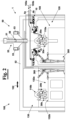
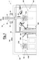
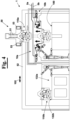
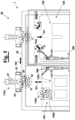
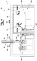
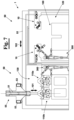
- figure 1 it is diagrammatically shown a first embodiment provided by the present invention of a machine 1 for producing packages of folded or interfolded laminar products made of paper material, in particular packages of napkins, tissues, towels, or similar products.
- the machine 1 comprises, in particular, a support frame 100 configured to support a feeding group 10 adapted to feed at least one web of paper 5, preferably a first and a second web of paper 5a and 5b, along a respective predetermined feeding direction 105a and 105b.
- the machine 1 comprises a folding or interfolding group 30 equipped with a first and a second folding or interfolding roll 31 and 32.
- a cutting group 20 is, furthermore, provided configured to cut the, or each, web of paper 5 into a respective plurality of sheets 6 of predetermined length.
- the folding or interfolding rolls 31 and 32 are configured to rotate about respective longitudinal rotation axes 131 and 132 in such a way to be counter-rotating with respect to each other, and to fold or interfold the or each aforementioned plurality of sheets of paper 6 at a folding or interfolding zone 35. In this way a stack 150 is obtained of sheets which are folded or interfolded according to a predetermined folding or interfolding configuration growing in height along a predetermined forming direction.
- the cutting group 20 and the folding or interfolding group 30 are mounted on the same support body 110.
- the support body 110 is configured to move between an assembled position, in which is supported by the support frame 100, and a disassembled position, in which is, instead, not supported by the support frame 100.
- the support body 110 can be positioned in a store area 130, for example in order to be subject to ordinary or extraordinary maintenance operations, before being positioned, again, in the machine 1, and precisely on the support frame 100.
- the machine 1 furthermore, comprises a displacement group 50 configured to displace the support body 110 between the assembled position and the disassembled position.
- the displacement group 50 and the support body 110 are provided with respective engagement portions 58 and 118 configured to engage with each other, in particular in a removable way, in such a way to allow the displacement group 50 to cause the displacement of the support body 110 between the assembled position and the disassembled position with respect to the support frame 100.
- the displacement group 50 is configured to cause the movement of the support body 110 from the assembled position to the disassembled position by lifting the same from the support frame 100, and the opposite movement, i.e. from the disassembled position to the assembled position, by lowering the support body on the support frame 100.
- the displacement group 50 can be configured to displace the support body 110 at least along a first displacement direction 101.
- the first direction 101 can be a direction orthogonal to the longitudinal axes 131 and 132 of the folding or interfolding rolls 31 and 32. More precisely, the first direction 101 can be the direction along which the displacement group 50 is adapted to cause the aforementioned lifting with respect to the support frame 100 to move the support body 110 same from the assembled position to the disassembled position, or the aforementioned lowering, to move, instead, the support body 110 from the disassembled position to the assembled position.
- the aforementioned displacement group 50 can be, furthermore, configured to displace the support body 110 along a second displacement direction 102.
- the aforementioned displacement direction 102 can be a direction orthogonal to the first displacement direction 101.
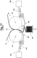
- the cutting group 20 can provide a first and a second cutting roll 21 and 22 associated respectively to the first and to the second folding or interfolding roll, 31 and 32. More precisely, the cutting rolls 21 and 22 can be peripherally provided with a predetermined number of blades, and rotate about respective longitudinal axes to cut and, therefore, to divide, a respective web of paper 5a, 5b into a respective plurality of sheets 6 by operating in combination with a respective fixed counter-blade.
- the cutting group 20 can be of the type described in WO2020161571 in the name of the same Applicant.
- the cutting group 20 can comprise a first and a second fixed cutting device 21 and 22 respectively associated to the first and to the second folding or interfolding roll 31 and 32.
- the first and the second cutting device 21 and 22 comprises, respectively, a base portion 25 provided with at least a cutting blade 26.
- the first and second folding or interfolding rolls 31 and 32 are provided with respective pluralities of counter-blades 36 distributed along the respective tubular body.
- each web 5a, or 5b, in a respective plurality of sheets 6 is carried out directly on the folding or interfolding rolls 31 and 32 which then provide to fold or interfold the sheets 6 same according to a predetermined folding or interfolding configuration.
- the folding or interfolding rolls, 31 and 32 can be also peripherally provided with recesses 36' and the aforementioned counter-blades 36 alternating to each other, in such a way to avoid that at the folding zone 35 the counter-blades 36 of a roll 31 or 32 can compromise the folding or interfolding operation and/or cut the worked sheets 6.
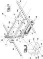
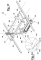
- the displacement group 50 can provide a first guide member 51 oriented along the first displacement direction 101, and, advantageously, a second guide member 52 oriented along a second displacement direction orthogonal to the aforementioned first displacement direction 101.
- the first guide member 51 can be mounted on a support member 55. This latter can be configured to slide along the second guide member 52.
- the support member 55 can comprise a base portion 56 and a sliding portion 57 configured to slide with respect to the base portion 56 along the aforementioned first guide member 51. More in particular, the sliding portion 57 can be provided with the engagement portion 58 configured to engage the respective engagement portion 118 of the support body 110.
- the sliding portion 57 can be provided with different engagement devices arranged to hook or engage the support body 110 to lift and to displace the same from and towards a store area 130, such as, for example, devices for providing a magnetic coupling, for example electromagnets, or a mechanical coupling.
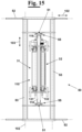
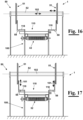
- the support member 55 can be configured to slide with respect to a third guide member 53 along a third displacement direction 103 orthogonal to the first and to the second displacement direction 101 and 102. In this way, it is possible to approach or move away the engagement portions 58 and 118 with respect to each other to cause them to move from the disengagement position shown in the figures 11 and 12 , to the engagement position shown in the figures 13 and 14 , and vice versa.
- the displacement group 50 can be a manipulator having at least two degrees of freedom.
- the two degrees of freedom are orthogonal to each other, but the possibility is also foreseen that the displacement group 50 can be configured to cause the movement of the support body 110 from the assembled position to the disassembled position, or vice versa, by a combination of movements comprising at least one translation and at least one rotation.
- the support member 55 can be adapted to move along the second guide member 52 and to be provided with two swinging arms, i.e. rotatably mounted on support member 55 and able to engage the support body 110 to lift the same from the support frame 100.
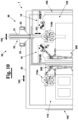
- the support member 55 can be configured to move, in particular integrally to the third guide member 53, with respect to the second guide member 52. In this way, it is possible to move the support member 55 and, therefore, the support body 110 that is supported by it, between a working area 120 and a store area 130. More in particular, within the store area 130 at least a second support body 110b can be positioned that have different characteristics, in particular in terms of size, with respect to the folding or interfolding group 30 and to the cutting members 20, in particular folding rolls 31b and 32b having a diameter different from the folding rolls 31a and 32a of a first support body 110a positioned within the working area 120, i.e. in the assembled position with respect to the support frame 100.
- the store area 130 and the working area 120 can be approached by at least one worker 300, advantageously through independent accesses 135 and 125, respectively.
- the worker 300 it is possible for the worker 300 to easily and quickly reach the aforementioned areas and any support body 110 that is in case positioned there in order to carry out ordinary or extraordinary maintenance operations.
- a worker whilst the paper converting line comprising the machine 1 is normally working, a worker can enter the store area 130 to carry out the maintenance operations on the support bodies 110 comprising the folding or interfolding group 30 and, if present, the cutting group 20.
- the displacement group 50 can be configured to alternately and selectively bring a first support body 110a in the disassembled position from the assembled position, and a second support body 110b from the disassembled position in the assembled position.
- each of the folding or interfolding rolls 31 and 32 can comprise a tubular body 33 configured to rotate about a respective longitudinal rotation axis 131 and 132.
- the tubular body 33 is provided with a plurality of suction holes 34 organized in a plurality of couples of longitudinal rows close to each other.
- a vacuum distribution device 38 can be, furthermore, provided that will not be described here in detail, but, for example, of the type that is described in EP1457444 or WO2020161571 , both in the name of the present Applicant.
- the vacuum distribution device 38 is configured to selectively pneumatically connect at least a vacuum generation device 250 to at least a row at a time of the aforementioned plurality of rows of suction holes 34, at predetermined angular positions of the tubular body 33, in such a way to cause the worked sheets of paper 6 to be sucked and to adhere at predetermined portions of the folding or interfolding roll 31 or 32.
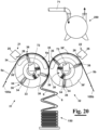
- the vacuum distribution device and the or each vacuum generation device 250 are pneumatically connected to each other by a connection duct 70.
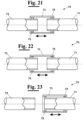
- This as diagrammatically shown in figure 20 , can comprise a first portion 71 integral to the vacuum distribution device 250 and a second portion 72, in particular a second portion 72 associated to each folding or interfolding roll 31 and 32, integral to the vacuum generation device 38.
- the first and second portions 71 and 72 can be adapted to move between a connection configuration ( figure 21 ), in which are adapted to pneumatically connect the vacuum generation device 250 to the vacuum distribution device 38, and a disconnection configuration ( figure 23 ), in which are adapted to pneumatically disconnect the vacuum distribution device 250 and the vacuum generation device 38.
- connection duct 70 can, furthermore, comprise a third portion 73 configured to move from a connection position ( figure 21 ) in which is adapted to pneumatically connect the first and the second portion of the connection duct 71 and 72 to each other that are, therefore, arranged in the connection configuration, and a disconnection position in which is adapted to pneumatically disconnect the first and second connection portions 71 and 72, which are, therefore, arranged in the aforementioned disconnection configuration.
- the third portion 73 can be slidingly mounted with respect to the first and second portions 71 and 72 of the connection duct 70 between the connection position, where is arranged in an advanced position, and the disconnection position, where is arranged in a retracted position. More in detail, at least one sealing element 75, for example an O-ring, positioned between the third portion 73 and the first and/or the second portion 71 and/or 72.
- the or each sealing element 75 can be configured to move from a working configuration, in which is adapted to exert a sealing action to pneumatically isolate the first and second portions 71 and 72 of the connection duct 70 from the external environment ( figure 21 ), and a rest configuration in which is not adapted to exert the aforementioned sealing action ( figures 22 and 23 ).
- the or each sealing element 75 can be pneumatically connected to an inflating device, which is not shown in figure for simplicity, adapted to cause the movement from the rest configuration to the working configuration, in particular by introducing air, or another gas, into each sealing element.
- the third portion 73 it is possible to cause the third portion 73 to slide from the connection position to the disconnection position and vice versa, when the or each sealing element 75 is in the rest configuration. More in particular, when the or each sealing element 75 is arranged in the working configuration, it can be adapted to prevent, or obstruct, the third portion 73 from sliding.
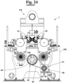
- the machine 1 comprises, furthermore, a motor group 40 configured to cause at least one between the first and second folding or interfolding rolls 31 and 32 to rotate about the respective rotation axis 131 and 132.
- the motor group 40 can be configured to operate the aforementioned rotation by a main motor 41 and a motion transmission device 42 configured to transmit the rotational motion of the rotation shaft, which is not shown in figure for simplicity, of the main motor 41 to at least one between the first and second folding or interfolding rolls 31 and 32.
- the motion transmission device 42 can comprise a first transmission member 43, for example a first toothed belt 43.
- the first transmission member 43 can mesh with a main deflection wheel 44 in such a way to cause it to rotate about a rotation axis 144.
- the motion transmission device 42 can comprise, furthermore, a rotation shaft 145 coaxially arranged to the main deflection wheel 44 and integral to it. Therefore, the aforementioned rotational motion of the main deflection wheel 44 causes also the rotation shaft 145 to rotate about the rotation axis 144.
- the motion transmission device 42 can comprise, furthermore, at least a second motion transmission member, for example a second toothed belt 45, which is mounted on the aforementioned rotation shaft 145 and on a series of guide pulleys 46 defining a predetermined sliding path.
- the second motion transmission member 45 is adapted to mesh with a motion transmission portion 37 integral to the first, or second folding or interfolding roll, 31 or 32, in such a way to cause a rotation about the respective longitudinal rotation axis 131 or 132.
- the group for adjusting the tension 60 can be configured to keep constant, or substantially constant, the tension of the motion transmission device 42, preferably of the second transmission member 45, in particular during the movement of the support body 110 between the assembled position and the disassembled position carried out by the displacement group 50.
- the second motion transmission member 45 in particular the toothed belt, is correctly positioned with respect to the different movable parts remaining on the support frame 100. Therefore, it is ensured that the different parts of the machine 1 are able to correctly work when the machine 1 is operated again and arranged in working conditions.
- the transmission of the motion of the motor shaft of the main motor 41 to the rotation shaft 145 can be obtained by using as motor shaft 145 the motor shaft of the main motor 41, i.e. mounting the same coaxially to the rotation axis 144.
- the group for adjusting the tension 60 comprises a measurement device 63, for example a force sensor, such as a load cell, advantageously configured to measure the tension on the second motion transmission member 45.
- a measurement device 63 for example a force sensor, such as a load cell, advantageously configured to measure the tension on the second motion transmission member 45.
- the measurement device 63 can be operatively connected to a processing device 200 configured to operate an actuation device 65.
- the actuation device 65 can be configured to cause a lengthening or a shortening of the path of the motion transmission member 45 depending on the tension signal detected by the aforementioned measurement device 63.
- the motion transmission belt 45 can be mounted on a series of guide pulleys or rollers 46 and 47 at least one of which able to move along a predetermined direction.
- the transmission belt 45 can be mounted on a series of fixed guide pulleys 46 and on at least one movable guide pulley 47, for example on two movable guide pulleys 47.
- the actuation device 65 can be arranged to lengthen or to shorten the path of the transmission belt 45 thus causing the or each movable guide pulley 47 to move away from the fixed guide pulleys 46.
- the actuation device 65 can comprise a motor 61 configured to cause the or each movable guide pulley 47 to move along a predetermined actuation direction 162 by an actuation device 65.
- the tension of the transmission belt 45 tends to gradually reduce that the aforementioned support body 110 is lifted and, therefore, progressively disengaged from the transmission belt 45.
- the group for adjusting the tension 60 can be operated by the processing device 200 to keep the tension of the transmission belt 45 constant or substantially constant, by operating the actuation device 65.
- the tension of the transmission belt 45 tends to increase during the positioning of a new support body 110 which engages with the motion transmission portion 37 of one between the folding or interfolding rolls 31 and 32.
- the group for adjusting the tension 60 can be operated by the processing device 200 to keep constant the tension of the transmission belt 45.
- the tension adjustment device 60 can be used also during the normal working conditions of the machine 1 to keep the transmission belt 45 constantly at a determined correct working tension. In this way both overloads and loosening, which could cause the loss of phase between the folding rolls 31 and 32 with other components of the machine 1 exposing to the risk of jamming, are avoided, or malfunctions in general that in the worst cases can cause the machine 1 to be damaged.
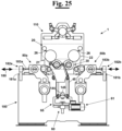
- the machine 1 can comprise, furthermore, a first and a second plurality of detaching fingers 85a and 85b configured to cause respectively the detachment of the folded or interfolded sheets of paper 6, from the first and second folding or interfolding roll 31 and 32, in particular from their external lateral surface.
- a first and a second driving group 80a and 80b are provided configured, respectively, to cause a oscillatory back and forth motion of the first and second pluralities of detaching fingers 85a and 85b towards the or from the folding or interfolding zone 35, in such a way to cause the detachment of the sheets of paper 6, respectively, from the first and second folding or interfolding roll 31 and 32.
- the first and second driving groups 80a and 80b can be configured to convert the rotational motion of a motor, or of a respective motor, in an oscillatory back and forth motion that is transmitted to the first and second pluralities of detaching fingers 85a and 85b.
- a transmission device can be provided operated by a main motor 41, not shown in the figure, configured to cause the first and second driving groups 80a and 80b to rotate and that is, therefore, converted in an oscillatory motion.
- the first and second driving groups 80a and 80b can be configured to bring, respectively, the first and second pluralities of detaching fingers 85a and 85b in a predetermined reference position, preferably corresponding to the position of top dead centre of the detaching fingers 85a and 85b during the respective back and forth motion.
- the reference position can be a position where the detaching fingers 85a and 85b do not have mechanical interference with other components of machine 1, in particular with the folding or interfolding rolls 31 and 32 and with the cutting blades 36.
- the first and second driving groups 80a and 80b are arranged to move, respectively, the first and second pluralities of detaching fingers 85a and 85b in the reference position before that the displacement group 50 is arranged to move the support body 110 between the assembled position and the disassembled position.
- the first and second driving groups 80a and 80b are arranged to move, respectively, the first and second pluralities of detaching fingers 85a and 85b in the reference position before that the displacement group 50 is arranged to move the support body 110 between the assembled position and the disassembled position.
- the first and second driving groups 80a and 80b can be configured to delay or anticipate the oscillatory motion of the first and second pluralities of detaching fingers 85a and 85b with respect to a predetermined reference oscillatory motion. In this way, it is possible to delay or anticipate the instant (tr) at which the first and second pluralities of detaching fingers 85a and 85b are arranged to cause the detachment of the sheets of paper 6 folded or interfolded, respectively from the first and the second folding or interfolding roll 31 and 32.
- This particular technical solution allows to adjust the motion of the detaching fingers 85a and 85b on the basis of the type of support body 110 installed in the machine 1, in particular of the diameter of the folding or interfolding rolls 31 and 32, of the number of blades 36 of which they are, in case, provided with, and of the other parameters of the cutting group 20 and/or of the folding or interfolding group 30 installed on the support body 110 arranged in the assembled position.
- the first and second driving groups 80a and 80b can be, advantageously, associated, respectively, to a first and a second phase adjustment device 90a and 90b configured to adjust the phase of the first and second pluralities of detaching fingers 85a and 85b with the respective folding or interfolding rolls 31 and 32.
- the first and the second phase adjustment device 90a and 90b are adapted to anticipate, or postpone, the instant tr at which the first and second pluralities of detaching fingers 85a, 85b are adapted to hit the web or sheet of paper to cause it to be detached from the respective folding or interfolding roll 31 and 32.
- the first and second phase adjustment devices 90a and 90b can comprise, respectively, a first and a second epicycloidal gear 95a, and 95b. More precisely, in this case, the first and second epicycloidal gear 95a and 95b can be operatively connected respectively to a first and a second motor group 91a and 91b, for example by a first transmission belt 87a, and 87b, and to a first and a second driving device 92a and 92b by a second transmission belt 88a and 88b. More precisely, the first and second driving device 92a and 92b are adapted to transmit the rotational motion generated by the first and second motor groups 91a and 91b, respectively to the first and to the second driving group 80a and 80b.
- the first and second epicycloidal gears 95a and 95b are, respectively, provided with a first and a second electric motor 96a and 96b. These are adapted to adjust the velocity of rotation of the first and of the second driving device 92a and 92b adjusting the velocity and the direction of rotation of a first and of a second epicycloidal gear, not shown in the figure for simplicity, housed, respectively, within the first and the second epicycloidal gear 95a and 95b.
- the first and second electric motors 96a and 96b can be normally still in such a way not to change the phase of the detaching fingers 85a and 85b with respect to the other parts of the machine 1, in particular the folding rolls 31 and 32. If it is necessary to change the phase of the first and of the second plurality of detaching fingers 85a and 85b, for example as a consequence of the replacement of a support body 110 with another, the first and the second electric motors 96a and 96b are operated to actuate, respectively, the first and second epicycloidal gears in such a way to temporarily accelerate or decelerate the second transmission belt 88a and 88b.
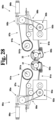
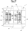
- the first and second driving groups 80a and 80b can be configured to translate one with respect to the other in order to approach or move away with respect to each other. In this way, it is possible to adjust the distance between them and in particular the distance with respect to the respective folding or interfolding rolls 31 and 32, in case that a support body 110 is replaced with another support body 110 equipped with folding or interfolding rolls 31 and 32 having a very different diameter with respect to the previous.
- the first and second driving groups 80a and 80b can be slidingly mounted along a predetermined sliding direction 180, in particular orthogonal to the axed 131 and 132 of the folding or interfolding rolls 31 and 32.
- first and second driving groups 80a and 80b can be mounted on a sliding group 185 configured to symmetrically approach or move away with respect to a plane of symmetry of the folding or interfolding rolls 31 and 32.
- first and second driving groups 80a and 80b can be mounted on a slide 181 arranged along the aforementioned sliding direction 180.
- a first and a second motor device 182a and 182b can be provided operatively connected, respectively, to the first and to the second driving group 80a and 80b by a respective connection member 183a and 183b.
- first and second connection members 183a and 183b for example an actuation rod
- the first and the second driving group 80a and 80b by operating, correspondingly, the first and second motor devices 182a and 182b.
- only one motor device 182 is provided configured to symmetrically move through a connection device 183 the first and second driving groups 80a and 80b.
- a step of positioning the detaching fingers 85a and 85b in a reference position can be provided at the moment of replacing a first support body 110a with a second support body 110b.
- the displacement group 50 can be, then, operated in such a way to engage the first support body 110a to be replaced at respective engagement portions 58 and 118.
- the engagement portions 58 and 118 can be provided with respective contacting surfaces 59 and 119.
- the engagement portions 58 and 118 can be provided, respectively, with at least a first contacting surface 59 and with at least a second contacting surface 119.
- the aforementioned contacting surfaces 59 and 119 of the engagement portions 58 and 118 are positioned in contact with each other ( figure 14 ).
- each engagement portion 58 and 118 is provided with 3 contacting surfaces 59 and 119.
- the engagement portions 58 and 118 can be configured in such a way that during the movement from the assembled position to the disassembled position and vice versa, no relative motion occurs between the aforementioned respective contacting surfaces 59 and 119, or, however, there is no significant relative motion, that means excluding relative motion due to vibrations, or stresses, produced on the same during the displacement by the displacement group 50.
- the contacting surface 119 of the engagement portion 118 is adapted to be in contact, for example to lay above, with the contacting surface 59 of the engagement portion 58 of the displacement group 50.
- the engagement portion 58 can provide a portion protruding from the sliding portion 57, advantageously orthogonal to this. More precisely, the engagement portion 58 protruding from the sliding portion 57 can be configured to laterally contain an end portion 118' of the engagement portion 118, for example substantially flat.
- the engagement portion 58 can be substantially "U-shaped" or "V-shaped”.
- a first and a second lateral wall 59'a and 59'b are adapted to laterally contain the engagement portion 118 at least at the aforementioned end portion 118' during the displacement between the assembled position and the disassembled position, in particular during the lifting or the lowering of the support body 110 with respect to the support frame 100 (see figure 14 ).
- the engagement portions 58 and 118 can be configured to interlock with each other.
- the first support body 110a once engaged can be displaced by the displacement group 50 at the store area 130 where is positioned at a determined storing position 132a. Then, the displacement group 50 engages a second support body 110b, in particular positioned at a corresponding storing position. The second support body 110b is, therefore, displaced by the displacement group 50 at the working area 120, and, then, positioned on the support frame 100. Once that the second support body 110b has been moved in the assembled position, the detaching fingers 85a and 85b are, then, moved from the reference position to the working position in order to start a new production cycle.
- connection duct 70 is of the type described above with reference to the figures from 21 to 23
- the steps can be, furthermore, provided of positioning the aforementioned first and second portions 71 and 72 in the disconnection configuration, before displacing by the displacement group 50 the first support body 110a from the working area 120 to the store area 130.
- the first and second portions 71 and 72 of the connection duct 70 are arranged in the connection configuration.
- the aforementioned step of engaging by the engagement portions the displacement group 50 and the support body 110 and of positioning the first and second portions 71 and 72 of the connection duct 70 in the disconnection position can be carried out simultaneously, or one before the other. The same can be said for the steps of positioning the first and second portions 71 and 72 of the connection duct 70 in the connection position and the positioning of the detaching fingers 85a and 85b from the reference position to the working position.
- a step can be provided of approaching or moving the detaching fingers 85a and 85b away with respect to each other, before displacing the support body 110a by the displacement group 50 to the store area 130.
- a step can be also provided of repositioning the detaching fingers 85a and 85b with respect to the folding or interfolding rolls 31 and 32 in a predetermined position before positioning the detaching fingers 85a and 85b in the working position.
- all the aforementioned steps, or at least a part of these, can be automatically managed, operated and controlled by the processing device 200.
- the new support body 110 has been positioned on the support frame 100, it is possible to block it by blocking devices in such a way to constrain their relative position.
- the blocking devices are not shown in the figure for simplicity.
- this further step can be omitted.
- the displacement group 50 comprises a first and a second support member 55a and 55b, advantageously, slidingly mounted on the same second guide member 52.
- each support member 55a and 55b can be configured to be positioned between a picking up position, at which is adapted to pick a respective support body 110 up, at the working area 120 or store area 130, and a waiting position, at which are adapted to engage outside the working area 120 and the store area 130, the support body 110 at the working area 120, or the store area 130, and then releasing the same at the store area 130, or the working area 120, where the aforementioned displacement of the support body 110 from the assembled position to the disassembled position can be carried out.
- the displacement group 50 is configured to move the support body 110 between the assembled position and the disassembled position by a rotation about at least a rotation axis 113, in particular parallel to the longitudinal rotation axes 131 and 132 of the folding or interfolding rolls 31 and 32.
- the displacement group 50 can comprise a first and a second displacement device 50a and 50b, for example a hydraulic, or pneumatic, or electromechanical, actuator, each of which operatively connected at a first engagement portion 50'a and 50'b to a respective support body 110a and 110b and pivotally connected, at a second engagement portion 50"a and 50"b, to the support frame 100.
- Each support body 110a and 110b can be, furthermore, pivotally connected to the support frame 100 at a respective point.
- a support body for example the support body 110b
- the respective displacement device 50b to cause the rotation of the support body 110a, or 110b, about a respective longitudinal rotation axis 113a, or 113b.
Landscapes
- Folding Of Thin Sheet-Like Materials, Special Discharging Devices, And Others (AREA)
Claims (15)
- Machine (1) permettant la production de paquets de produits stratifiés pliés ou entrepliés en un matériau de papier, en particulier des paquets de serviettes, de mouchoirs, d'essuie-tout ou de produits similaires, ladite machine (1) comprenant un cadre de support (100) conçu pour supporter :- un groupe d'alimentation (10) conçu pour acheminer respectivement une première et une seconde bande de papier (5a, 5b) le long d'une première et d'une seconde direction d'acheminement prédéfinies (105a, 105b);- un groupe de coupe (20) conçu pour couper respectivement lesdites première et seconde bandes de papier (5a, 5b) en une première et une seconde pluralité de feuilles de papier (6) d'une longueur prédéfinie ;- un groupe de pliage ou d'entrepliage (30) équipé d'un premier et d'un second cylindre de pliage contrarotatif (31, 32) adaptés pour tourner autour d'axes de rotation longitudinaux respectifs (131, 132) et conçus pour plier ou entreplier lesdites première et seconde pluralités de feuilles de papier (6) au niveau d'une zone de pliage ou d'entrepliage (35) de telle façon à obtenir une pile (150) de feuilles pliées ou entrepliées selon une configuration de pliage ou d'entrepliage prédéfinie, ledit groupe de coupe (20) et ledit groupe de pliage ou d'entrepliage (30) étant montés sur un même corps de support (110) conçu pour se déplacer entre une position assemblée dans laquelle il est adapté pour être supporté par ledit cadre de support (100) et une position non assemblée dans laquelle il n'est pas adapté pour être supporté par ledit cadre de support (100) ;- un groupe de transfert (50) conçu pour transférer ledit corps de support (110) entre ladite position assemblée et ladite position non assemblée ;ladite machine (1) étant caractérisée en ce que ledit groupe de transfert (50) est conçu pour transférer ledit corps de support (110) de ladite position assemblée à ladite position non assemblée en soulevant ledit corps de support (110) dudit cadre de support (100), et pour transférer ledit corps de support (110) de ladite position non assemblée à ladite position assemblée en abaissant ledit corps de support (110) sur ledit cadre de support (100), et en ce que ledit groupe de transfert (50) et ledit corps de support (110) sont dotés de parties de mise en prise respectives (58, 118) conçues pour venir en prise l'une avec l'autre de telle façon à permettre audit groupe de transfert (50) de transférer ledit corps de support (110) entre ladite position assemblée et ladite position non assemblée par rapport audit cadre de support (100).
- Machine (1), selon la revendication 1, ledit groupe de transfert (50) étant conçu pour transférer ledit corps de support (110) le long d'une première direction de transfert (101) le long de laquelle il est adapté pour soulever ou abaisser ledit corps de support (110) par rapport audit cadre de support (100), et au moins le long d'une seconde direction de transfert (102).
- Machine (1), selon la revendication 2, lesdites première et seconde directions de transfert (101, 102) étant orthogonales l'une par rapport à l'autre.
- Machine (1) selon la revendication 2, ledit groupe de transfert (50) fournissant :- un premier élément de guidage (51) orienté le long de ladite première direction de transfert (101) ;- un second élément de guidage (52) orienté le long de ladite seconde direction de transfert (102) ;- un élément de support (55) conçu pour coulisser le long dudit second élément de guidage (52), ledit élément de support (55) étant pourvu de :- une partie base (56) dotée dudit premier élément de guidage (51) ;- une partie coulissante (57) adaptée pour être montée coulissante le long dudit premier élément de guidage (51) par rapport à ladite partie base (56), ladite partie coulissante (57) étant dotée de ladite partie de mise en prise (58).
- Machine (1) selon l'une quelconque des revendications précédentes, un groupe moteur (40) étant, en outre, prévu conçu pour amener au moins un parmi ledit premier et ledit second cylindre de pliage ou d'entrepliage (31, 32) à tourner autour d'un axe de rotation respectif (131, 132), ledit groupe moteur (40) comprenant :- un moteur principal (41) ;- un dispositif de transmission de mouvement (42) comprenant au moins un élément de transmission de mouvement (45) conçu pour transmettre le mouvement de rotation d'un arbre de rotation dudit moteur principal (41) à au moins un parmi ledit premier et ledit second cylindre de pliage ou d'entrepliage (31, 32).
- Machine (1) selon la revendication 5, un groupe destiné au réglage de la tension (60) étant en outre prévu, conçu pour régler la tension dudit élément de transmission de mouvement
(42), ledit groupe pour régler la tension (60) étant conçu pour maintenir sensiblement constante la tension dudit élément de transmission de mouvement (45) durant le mouvement dudit corps de support (110) entre ladite position assemblée et ladite position non assemblée effectué par ledit groupe de transfert (50). - Machine (1) selon la revendication 6, ledit groupe pour régler la tension (60) comprenant un dispositif de mesure (63) conçu pour mesurer la tension sur ledit élément de transmission de mouvement (45), ledit dispositif de mesure (63) étant connecté de manière fonctionnelle à un dispositif de traitement (200) conçu pour faire fonctionner un dispositif d'actionnement (65) conçu pour entraîner un allongement ou un raccourcissement du trajet dudit élément de transmission de mouvement (45) selon un signal de tension mesuré par ledit dispositif de mesure (63), ledit élément de transmission de mouvement (45) étant monté de manière coulissante le long d'un trajet prédéfini défini par une pluralité de poulies de guidage (46, 47) et ledit dispositif d'actionnement (65) étant conçu pour rapprocher lesdites poulies de guidage (46, 47) les unes des autres, de telle façon à entraîner un raccourcissement dudit trajet, ou à éloigner lesdites poulies de guidage (46, 47) les unes des autres, de telle façon à entraîner un allongement dudit trajet.
- Machine (1) selon l'une quelconque des revendications précédentes, chacun dudit premier et dudit second cylindre de pliage ou d'entrepliage (31, 32) comprenant :- un corps tubulaire (33) conçu pour tourner autour d'un axe de rotation longitudinal respectif (131, 132), ledit
corps tubulaire (33) étant doté d'une pluralité de trous d'aspiration (34) organisés en une pluralité de paires de rangées longitudinales proches l'une de l'autre ;- un dispositif de distribution de vide (38) conçu pour raccorder pneumatiquement de manière sélective un dispositif de génération de vide (250) conçu pour générer un degré de vide prédéfini au moins au niveau d'une rangée de la pluralité susmentionnée de rangées de trous d'aspiration (34) au niveau de positions angulaires prédéfinies dudit corps tubulaire (33), de telle façon à amener lesdites première et seconde pluralités de feuilles de papier travaillées (6) à être aspirées et, par conséquent, à adhérer au niveau de parties prédéfinies dudit cylindre de pliage ou d'entrepliage (31, 32), ledit dispositif de distribution de vide et ledit dispositif de génération de vide étant adaptés pour être raccordés ou séparés pneumatiquement par un conduit de raccordement (70) comprenant :- une première partie (71) solidaire audit dispositif de distribution de vide (38) ;- une deuxième partie (72) solidaire audit dispositif de génération de vide (250), lesdites première et deuxième parties (71, 72) étant conçues pour se déplacer entre une configuration de raccordement dans laquelle elles sont adaptées pour raccorder pneumatiquement ledit dispositif de génération de vide (250) audit dispositif de distribution de vide (38), et une configuration de séparation dans laquelle elles sont adaptés pour raccorder pneumatiquement ledit dispositif de distribution de vide (38) audit dispositif de génération de vide (250) ;- une troisième partie (73) conçue pour entraîner ledit mouvement desdites première et seconde parties du conduit de raccordement (71, 72) entre ladite configuration de raccordement et ladite configuration de séparation,ladite troisième partie (73) étant adaptée pour être montée coulissante par rapport auxdites première et deuxième parties (71, 72) dudit conduit de raccordement (70) entre une position rétractée correspondant à ladite configuration de séparation, et une position avancée correspondant à ladite configuration de raccordement, et au moins un élément d'étanchéité (75) étant, en outre, prévu positionné entre ladite troisième partie (73) et ladite première et/ou ladite deuxième partie (71, 72). - Machine selon l'une quelconque des revendications précédentes, ledit groupe de coupe (20) comprenant un premier et un second dispositif de coupe (21, 22) dotés, respectivement, d'au moins une première et une seconde lame de coupe (26) associées, respectivement, audit premier et audit second cylindre de pliage ou d'entrepliage (31, 32), et lesdits premier et second cylindres de pliage ou d'entrepliage (31, 32) étant, respectivement, dotés d'une première et d'une seconde pluralité de contre-lames (36) conçues pour travailler, respectivement, en combinaison avec lesdites première et seconde lames de coupe (26) afin de couper ladite bande de papier respective (5a, 5b) en ladite pluralité de feuilles de papier respective (6).
- Machine, selon l'une quelconque des revendications précédentes, étant également prévus :- une première et une seconde pluralité de doigts de détachement (85a, 85b) conçus, respectivement, pour amener lesdites feuilles de papier pliées ou entrepliées (6) à se détacher dudit premier et dudit second cylindre de pliage ou d'entrepliage (31, 32) ;- un premier et un second groupe d'entraînement (80a, 80b) conçus, respectivement, pour entraîner un mouvement oscillant de va-et-vient dudit premier et de ladite seconde pluralité de doigts de détachement (85a, 85b) vers/depuis ladite zone de pliage ou d'entrepliage (35) de telle façon à amener lesdites feuilles de papier pliées ou entrepliées (6) à se détacher dudit premier et dudit second cylindre de pliage ou d'entrepliage (31, 32), lesdits premier et second groupes d'entraînement (80a, 80b) étant adaptés pour déplacer, respectivement, ladite première et ladite seconde pluralité de doigts de détachement (85a, 85b) dans une position de référence prédéfinie avant que ledit groupe de transfert (50) ne soit adapté pour déplacer ledit corps de support (110) entre ladite position assemblée et ladite position non assemblée.
- Machine selon l'une quelconque des revendications précédentes, lesdites parties de mise en prise (58, 118) étant dotées de surfaces de contact respectives (59, 119) positionnées en contact l'une avec l'autre durant ledit mouvement par ledit groupe de transfert (50) entre ladite position assemblée et ladite position non assemblée, et lesdites parties de mise en prise (58, 118) étant conçues d'une telle façon que durant ledit mouvement par ledit groupe de transfert (50) entre ladite position assemblée et ladite position non assemblée, lesdites surfaces de contact (59, 119) ne se déplacent pas l'une par rapport à l'autre.
- Procédé permettant la production de paquets de produits stratifiés en un matériau en papier plié ou entreplié, en particulier de paquets de serviettes, de mouchoirs, d'essuie-tout ou de produits similaires, ledit procédé comprenant les étapes de :- acheminement d'une première et d'une seconde bande de papier (5a, 5b), respectivement, le long d'une première et d'une seconde direction d'acheminement ;- coupe par un groupe de coupe (20) desdites première et seconde bandes de papier respectivement en une première et une seconde pluralité de feuilles (6) d'une longueur prédéfinie ;- pliage ou entrepliage desdites première et seconde pluralités de feuilles de papier au niveau d'une zone de pliage ou d'entrepliage prédéfinie (35),ladite étape de pliage ou d'entrepliage étant effectuée par un groupe de pliage ou d'entrepliage (30) comprenant un premier et un second cylindre contrarotatif de pliage ou d'entrepliage (31, 32) entre lesquels ladite zone de pliage ou d'entrepliage (35) est définie ;ledit groupe de coupe et ledit groupe de pliage ou d'entrepliage étant montés sur un même corps de support (110) conçu pour se déplacer entre une position assemblée où il est supporté par un cadre de support, et une position non assemblée, où il n'est pas supporté par ledit cadre de support ;- transfert dudit corps de support (110) entre ladite position assemblée et ladite position non assemblée ;ledit procédé étant caractérisé en ce que ladite étape de transfert est effectuée en mettant en prise un groupe de transfert (50) et ledit corps de support (110) au niveau des parties de mise en prise respectives (58, 118) et en soulevant ledit corps de support (110) au moyen dudit groupe de transfert (50) de telle façon à permettre audit groupe de transfert (50) d'entraîner ledit transfert dudit corps de support (110) de ladite position assemblée à ladite position non assembléeet en abaissant ledit corps de support (110) au moyen dudit groupe de transfert (50) de telle façon à permettre audit groupe de transfert (50) d'entraîner ledit transfert dudit corps de support (110) de ladite position non assemblée à ladite position assemblée par rapport audit cadre de support (100).
- Procédé, selon la revendication 12, un premier et un second corps de support (110a, 110b) étant prévus et étant prévues les étapes de :- mise en prise par ladite partie de mise en prise (58, 118) dudit premier corps de support (110a) et dudit groupe de transfert (50) au niveau d'une zone de travail (120) ;- soulèvement dudit premier corps de support (110a) positionné au niveau de ladite zone de travail (120) au moyen dudit groupe de transfert (50) pour déplacer ledit premier corps de support (110a) de ladite position assemblée à ladite position non assemblée ;- transfert dudit premier corps de support (110a) au moyen dudit groupe de transfert (50) de ladite zone de travail (120) à une zone de stockage (130) ;- positionnement dudit premier corps de support (110a) au niveau d'une première position de stockage (132a) qui est présente au niveau de ladite zone de stockage (130) ;- séparation dudit premier corps de support (110a) et dudit groupe de transfert (50) ;- positionnement dudit groupe de transfert (50) au niveau d'une seconde position de stockage (132b) qui est présente au niveau de ladite zone de stockage (130) au niveau de laquelle ledit second corps de support (110b) est positionné ;- mise en prise par lesdites parties de mise en prise (58, 118) dudit second corps de support (110b) et dudit groupe de transfert (50) ;- transfert dudit second corps de support (110b) de ladite zone de stockage (130) à ladite zone de travail (120) ;- abaissement au niveau de ladite zone de travail (120) dudit second corps de support (110b) au moyen dudit groupe de transfert (50) pour déplacer ledit second corps de support (110b) de ladite position non assemblée à ladite position assemblée ;- séparation dudit second corps de support (110b) et dudit groupe de transfert (50) amenant lesdites parties de mise en prise respectives à se déplacer de ladite position de mise en prise à ladite position de séparation.
- Procédé selon la revendication 24, une première et une seconde pluralité de doigts de détachement (85a, 85b) étant, en outre, prévus conçus pour amener lesdites feuilles de papier pliées ou entrepliées (6) à se détacher respectivement dudit premier et dudit second cylindre de pliage ou d'entrepliage (31, 32) et étant, en outre, prévues les étapes de :- positionnement desdits doigts de détachement (85a, 85b) dans une position de référence prédéfinie ;- transfert par ledit groupe de transfert (50) dudit premier corps de support (110) de ladite zone de travail (120) à ladite zone de stockage (130) ;- transfert par ledit groupe de transfert (50) dudit second corps de support (110) de ladite zone de stockage (130) à ladite zone de travail (120) ;- positionnement desdits doigts de détachement (85a, 85b) de ladite position de référence à une position de travail.
- Procédé selon la revendication 14, un dispositif de distribution de vide (38) étant, en outre, prévu conçu pour raccorder pneumatiquement de manière sélective un dispositif de génération de vide (250) conçu pour générer un degré de vide prédéfini avec au moins une rangée de la pluralité susmentionnée de rangées de trous d'aspiration (34), au niveau de positions angulaires prédéfinies dudit corps tubulaire (33), de telle façon à amener lesdites première et seconde pluralités de feuilles de papier travaillées (6) à être aspirées et, par conséquent, à adhérer au niveau de parties prédéfinies dudit cylindre de pliage ou d'entrepliage (31, 32), ledit dispositif de distribution de vide et ledit dispositif de génération de vide étant adaptés pour être raccordés ou séparés pneumatiquement par un conduit de raccordement (70) comprenant :- une première partie (71) solidaire audit dispositif de distribution de vide (38) ;- une deuxième partie (72) solidaire audit dispositif de génération de vide (250), lesdites première et deuxième parties (71, 72) étant conçues pour se déplacer entre une configuration de raccordement dans laquelle elles sont adaptées pour raccorder pneumatiquement ledit dispositif de génération de vide (250) audit dispositif de distribution de vide (38), et une configuration de séparation dans laquelle elles sont adaptés pour séparer pneumatiquement ledit dispositif de distribution de vide (250) dudit dispositif de génération de vide (38) ;et étant prévues les étapes de :- entraînement dudit mouvement desdites première et deuxième parties (71, 72) de ladite configuration de raccordement à ladite configuration de séparation, avant le transfert par ledit groupe de transfert (50) dudit premier corps de support (110a) de ladite zone de travail (120) à ladite zone de stockage (130) ;- entraînement dudit mouvement desdites première et deuxième parties (71, 72) de ladite configuration de séparation à ladite configuration de raccordement, une fois qu'a été transféré, par ledit groupe de transfert (50), ledit second corps de support (110b) de ladite zone de stockage (130) à ladite zone de travail (120), jusqu'à ladite position assemblée.
Applications Claiming Priority (2)
| Application Number | Priority Date | Filing Date | Title |
|---|---|---|---|
| IT202100022133 | 2021-08-20 | ||
| PCT/IB2022/057554 WO2023021386A1 (fr) | 2021-08-20 | 2022-08-12 | Machine pour produire des produits stratifiés en un matériau papier, en particulier des paquets de serviettes, de mouchoirs ou de produits similaires et procédé de production associé |
Publications (3)
| Publication Number | Publication Date |
|---|---|
| EP4387910A1 EP4387910A1 (fr) | 2024-06-26 |
| EP4387910C0 EP4387910C0 (fr) | 2025-06-04 |
| EP4387910B1 true EP4387910B1 (fr) | 2025-06-04 |
Family
ID=78463828
Family Applications (1)
| Application Number | Title | Priority Date | Filing Date |
|---|---|---|---|
| EP22768470.1A Active EP4387910B1 (fr) | 2021-08-20 | 2022-08-12 | Machine pour produire des produits stratifiés en un matériau papier, en particulier des paquets de serviettes, de mouchoirs ou de produits similaires et procédé de production associé |
Country Status (4)
| Country | Link |
|---|---|
| US (1) | US12600595B2 (fr) |
| EP (1) | EP4387910B1 (fr) |
| CN (1) | CN118043274A (fr) |
| WO (1) | WO2023021386A1 (fr) |
Families Citing this family (3)
| Publication number | Priority date | Publication date | Assignee | Title |
|---|---|---|---|---|
| IT202200002804A1 (it) * | 2022-02-16 | 2023-08-16 | Ot Lucca S R L | Impianto con macchina interfogliatrice, metodo e macchina interfogliatrice |
| WO2025174544A1 (fr) | 2024-02-14 | 2025-08-21 | Bw Converting, Inc. | Machine de traitement d'une bande de matériau, et procédé de changement de rouleaux sur une machine |
| IT202400006502A1 (it) * | 2024-03-25 | 2024-06-25 | Ot Lucca S R L | Macchina interfogliatrice multiformato e metodo per variare formato |
Family Cites Families (11)
| Publication number | Priority date | Publication date | Assignee | Title |
|---|---|---|---|---|
| US3490762A (en) | 1967-09-07 | 1970-01-20 | Paper Converting Machine Co | Web-lapping machine |
| US5598758A (en) * | 1993-07-22 | 1997-02-04 | Moore Business Forms, Inc. | Quick change cassette hole punch unit |
| EP0982255B1 (fr) | 1998-08-21 | 2006-12-20 | M T C - Macchine Trasformazione Carta S.r.l. | Procédé pour le pliage enchevêtré de materiau en feuille et dispositif pour la mise en oeuvre de ce procédé |
| PT1156004E (pt) * | 2000-05-15 | 2006-11-30 | Heidelberger Druckmasch Ag | Dispositivo de dobrar |
| CH694985A5 (fr) * | 2002-01-24 | 2005-10-31 | Bobst Sa | Dispositif pour le montage d'une cassette, comportant des outils cylindriques, dans une machine de façonnage rotatif d'une matière en bande ou en feuille. |
| EP1457444B2 (fr) | 2003-02-18 | 2018-10-24 | M T C - Macchine Trasformazione Carta S.r.l. | Machine de pliage enchevetre d'une bande ou de feuilles de papier avec un rouleau transporteur a vide |
| US7121994B2 (en) * | 2003-09-30 | 2006-10-17 | Fpna Acquisition Corporation | Assembly for and method of adjusting the phasing of folding rolls to create a fold in sheets of material |
| US7407161B2 (en) | 2003-10-01 | 2008-08-05 | Fpna Acquisition Corporation | Method of and assembly for lapping consecutive sheets of web material |
| ES2344895T3 (es) * | 2004-08-31 | 2010-09-09 | M T C - Macchine Trasformazione Carta S.R.L. | Estructura de una maquina de plegado. |
| EP2422971B1 (fr) * | 2010-08-31 | 2014-03-26 | Heidelberger Druckmaschinen AG | Dispositif de réception d'outil |
| US10196228B2 (en) * | 2016-04-28 | 2019-02-05 | Dmt Solutions Global Corporation | Method and apparatus for adjusting fold roller gaps |
-
2022
- 2022-08-12 CN CN202280055409.6A patent/CN118043274A/zh active Pending
- 2022-08-12 EP EP22768470.1A patent/EP4387910B1/fr active Active
- 2022-08-12 WO PCT/IB2022/057554 patent/WO2023021386A1/fr not_active Ceased
- 2022-08-12 US US18/685,169 patent/US12600595B2/en active Active
Also Published As
| Publication number | Publication date |
|---|---|
| WO2023021386A1 (fr) | 2023-02-23 |
| EP4387910C0 (fr) | 2025-06-04 |
| CN118043274A (zh) | 2024-05-14 |
| US20240351819A1 (en) | 2024-10-24 |
| EP4387910A1 (fr) | 2024-06-26 |
| US12600595B2 (en) | 2026-04-14 |
Similar Documents
| Publication | Publication Date | Title |
|---|---|---|
| US12600595B2 (en) | Machine for producing laminar products made of paper material, in particular packages of napkins, tissues or similar products and related production method | |
| US8123665B2 (en) | Multi-fold interfolding machine structure | |
| EP2462044B1 (fr) | Structure de machine de pliage et d'empilement de feuilles à usage multiple | |
| US8419002B2 (en) | High speed interfolder separator | |
| US8882098B2 (en) | High speed interfolder separator | |
| US20060073007A1 (en) | Method and apparatus for separating packages of interfolded sheets at high flexibility | |
| US11629029B2 (en) | Folding, or interfolding, unit for folding, or interfolding sheets of paper for a machine for paper converting | |
| EP3625131B1 (fr) | Machine d'emballage | |
| US20230416042A1 (en) | Folding, or interfolding, unit of a web, or sheet, of paper in a paper converting machine | |
| US20240199363A1 (en) | Machine and method for producing packages of folded or interfolded laminar products made of paper, in particular packages of napkins, tissues, towels, or similar products | |
| CA2346276C (fr) | Dispositif de positionnement de feuilles a un poste de machine | |
| US20220267114A1 (en) | Sheet processing machine comprising at least one pile formation device, and method for forming piles | |
| US11891258B2 (en) | Sheet processing machine comprising at least one pile formation device, and method for forming piles | |
| US12617644B2 (en) | Suction roll of a web, or sheet, of paper in a paper converting machine | |
| US20220315371A1 (en) | Die-cutting machine comprising a transport system configured as a chain gripper system and method for opening at least one holding element | |
| IT202100011531A1 (it) | Unita’ di piega, o interfogliatura, di fogli di carta in una macchina per la trasformazione della carta | |
| CN114803668A (zh) | 多机械手纸巾分叠机构 | |
| WO2024161360A1 (fr) | Machine de production de piles de produits laminaires en papier et procédé de production associé |
Legal Events
| Date | Code | Title | Description |
|---|---|---|---|
| STAA | Information on the status of an ep patent application or granted ep patent |
Free format text: STATUS: UNKNOWN |
|
| STAA | Information on the status of an ep patent application or granted ep patent |
Free format text: STATUS: THE INTERNATIONAL PUBLICATION HAS BEEN MADE |
|
| PUAI | Public reference made under article 153(3) epc to a published international application that has entered the european phase |
Free format text: ORIGINAL CODE: 0009012 |
|
| STAA | Information on the status of an ep patent application or granted ep patent |
Free format text: STATUS: REQUEST FOR EXAMINATION WAS MADE |
|
| 17P | Request for examination filed |
Effective date: 20240313 |
|
| AK | Designated contracting states |
Kind code of ref document: A1 Designated state(s): AL AT BE BG CH CY CZ DE DK EE ES FI FR GB GR HR HU IE IS IT LI LT LU LV MC MK MT NL NO PL PT RO RS SE SI SK SM TR |
|
| DAV | Request for validation of the european patent (deleted) | ||
| DAX | Request for extension of the european patent (deleted) | ||
| GRAP | Despatch of communication of intention to grant a patent |
Free format text: ORIGINAL CODE: EPIDOSNIGR1 |
|
| STAA | Information on the status of an ep patent application or granted ep patent |
Free format text: STATUS: GRANT OF PATENT IS INTENDED |
|
| RIC1 | Information provided on ipc code assigned before grant |
Ipc: B65H 45/28 20060101ALI20241210BHEP Ipc: B65H 45/16 20060101ALI20241210BHEP Ipc: B65H 45/20 20060101ALI20241210BHEP Ipc: B65H 45/24 20060101AFI20241210BHEP |
|
| INTG | Intention to grant announced |
Effective date: 20250102 |
|
| GRAS | Grant fee paid |
Free format text: ORIGINAL CODE: EPIDOSNIGR3 |
|
| GRAA | (expected) grant |
Free format text: ORIGINAL CODE: 0009210 |
|
| STAA | Information on the status of an ep patent application or granted ep patent |
Free format text: STATUS: THE PATENT HAS BEEN GRANTED |
|
| AK | Designated contracting states |
Kind code of ref document: B1 Designated state(s): AL AT BE BG CH CY CZ DE DK EE ES FI FR GB GR HR HU IE IS IT LI LT LU LV MC MK MT NL NO PL PT RO RS SE SI SK SM TR |
|
| REG | Reference to a national code |
Ref country code: GB Ref legal event code: FG4D |
|
| REG | Reference to a national code |
Ref country code: CH Ref legal event code: EP |
|
| REG | Reference to a national code |
Ref country code: DE Ref legal event code: R096 Ref document number: 602022015607 Country of ref document: DE |
|
| REG | Reference to a national code |
Ref country code: IE Ref legal event code: FG4D |
|
| U01 | Request for unitary effect filed |
Effective date: 20250624 |
|
| U07 | Unitary effect registered |
Designated state(s): AT BE BG DE DK EE FI FR IT LT LU LV MT NL PT RO SE SI Effective date: 20250701 |
|
| U20 | Renewal fee for the european patent with unitary effect paid |
Year of fee payment: 4 Effective date: 20250827 |
|
| PG25 | Lapsed in a contracting state [announced via postgrant information from national office to epo] |
Ref country code: ES Free format text: LAPSE BECAUSE OF FAILURE TO SUBMIT A TRANSLATION OF THE DESCRIPTION OR TO PAY THE FEE WITHIN THE PRESCRIBED TIME-LIMIT Effective date: 20250604 |
|
| PG25 | Lapsed in a contracting state [announced via postgrant information from national office to epo] |
Ref country code: GR Free format text: LAPSE BECAUSE OF FAILURE TO SUBMIT A TRANSLATION OF THE DESCRIPTION OR TO PAY THE FEE WITHIN THE PRESCRIBED TIME-LIMIT Effective date: 20250905 Ref country code: NO Free format text: LAPSE BECAUSE OF FAILURE TO SUBMIT A TRANSLATION OF THE DESCRIPTION OR TO PAY THE FEE WITHIN THE PRESCRIBED TIME-LIMIT Effective date: 20250904 |
|
| PG25 | Lapsed in a contracting state [announced via postgrant information from national office to epo] |
Ref country code: PL Free format text: LAPSE BECAUSE OF FAILURE TO SUBMIT A TRANSLATION OF THE DESCRIPTION OR TO PAY THE FEE WITHIN THE PRESCRIBED TIME-LIMIT Effective date: 20250604 |
|
| PG25 | Lapsed in a contracting state [announced via postgrant information from national office to epo] |
Ref country code: HR Free format text: LAPSE BECAUSE OF FAILURE TO SUBMIT A TRANSLATION OF THE DESCRIPTION OR TO PAY THE FEE WITHIN THE PRESCRIBED TIME-LIMIT Effective date: 20250604 |
|
| PG25 | Lapsed in a contracting state [announced via postgrant information from national office to epo] |
Ref country code: RS Free format text: LAPSE BECAUSE OF FAILURE TO SUBMIT A TRANSLATION OF THE DESCRIPTION OR TO PAY THE FEE WITHIN THE PRESCRIBED TIME-LIMIT Effective date: 20250904 |
|
| PG25 | Lapsed in a contracting state [announced via postgrant information from national office to epo] |
Ref country code: IS Free format text: LAPSE BECAUSE OF FAILURE TO SUBMIT A TRANSLATION OF THE DESCRIPTION OR TO PAY THE FEE WITHIN THE PRESCRIBED TIME-LIMIT Effective date: 20251004 |
|
| PG25 | Lapsed in a contracting state [announced via postgrant information from national office to epo] |
Ref country code: SM Free format text: LAPSE BECAUSE OF FAILURE TO SUBMIT A TRANSLATION OF THE DESCRIPTION OR TO PAY THE FEE WITHIN THE PRESCRIBED TIME-LIMIT Effective date: 20250604 |
|
| PG25 | Lapsed in a contracting state [announced via postgrant information from national office to epo] |
Ref country code: CZ Free format text: LAPSE BECAUSE OF FAILURE TO SUBMIT A TRANSLATION OF THE DESCRIPTION OR TO PAY THE FEE WITHIN THE PRESCRIBED TIME-LIMIT Effective date: 20250604 |
|
| PG25 | Lapsed in a contracting state [announced via postgrant information from national office to epo] |
Ref country code: SK Free format text: LAPSE BECAUSE OF FAILURE TO SUBMIT A TRANSLATION OF THE DESCRIPTION OR TO PAY THE FEE WITHIN THE PRESCRIBED TIME-LIMIT Effective date: 20250604 |
|
| REG | Reference to a national code |
Ref country code: CH Ref legal event code: H13 Free format text: ST27 STATUS EVENT CODE: U-0-0-H10-H13 (AS PROVIDED BY THE NATIONAL OFFICE) Effective date: 20260324 |
|
| PG25 | Lapsed in a contracting state [announced via postgrant information from national office to epo] |
Ref country code: MC Free format text: LAPSE BECAUSE OF FAILURE TO SUBMIT A TRANSLATION OF THE DESCRIPTION OR TO PAY THE FEE WITHIN THE PRESCRIBED TIME-LIMIT Effective date: 20250604 |
|
| PLBE | No opposition filed within time limit |
Free format text: ORIGINAL CODE: 0009261 |
|
| STAA | Information on the status of an ep patent application or granted ep patent |
Free format text: STATUS: NO OPPOSITION FILED WITHIN TIME LIMIT |
|
| REG | Reference to a national code |
Ref country code: CH Ref legal event code: L10 Free format text: ST27 STATUS EVENT CODE: U-0-0-L10-L00 (AS PROVIDED BY THE NATIONAL OFFICE) Effective date: 20260416 |
|
| PG25 | Lapsed in a contracting state [announced via postgrant information from national office to epo] |
Ref country code: CH Free format text: LAPSE BECAUSE OF NON-PAYMENT OF DUE FEES Effective date: 20250831 |
|
| 26N | No opposition filed |
Effective date: 20260305 |