EP4388075B1 - Vorrichtung zur mikroskopischen wurmbeobachtung - Google Patents
Vorrichtung zur mikroskopischen wurmbeobachtung Download PDFInfo
- Publication number
- EP4388075B1 EP4388075B1 EP22764796.3A EP22764796A EP4388075B1 EP 4388075 B1 EP4388075 B1 EP 4388075B1 EP 22764796 A EP22764796 A EP 22764796A EP 4388075 B1 EP4388075 B1 EP 4388075B1
- Authority
- EP
- European Patent Office
- Prior art keywords
- chip
- microfluidic
- pump
- reservoirs
- hollow tubes
- Prior art date
- Legal status (The legal status is an assumption and is not a legal conclusion. Google has not performed a legal analysis and makes no representation as to the accuracy of the status listed.)
- Active
Links
Images


Classifications
-
- C—CHEMISTRY; METALLURGY
- C12—BIOCHEMISTRY; BEER; SPIRITS; WINE; VINEGAR; MICROBIOLOGY; ENZYMOLOGY; MUTATION OR GENETIC ENGINEERING
- C12Q—MEASURING OR TESTING PROCESSES INVOLVING ENZYMES, NUCLEIC ACIDS OR MICROORGANISMS; COMPOSITIONS OR TEST PAPERS THEREFOR; PROCESSES OF PREPARING SUCH COMPOSITIONS; CONDITION-RESPONSIVE CONTROL IN MICROBIOLOGICAL OR ENZYMOLOGICAL PROCESSES
- C12Q1/00—Measuring or testing processes involving enzymes, nucleic acids or microorganisms; Compositions therefor; Processes of preparing such compositions
- C12Q1/02—Measuring or testing processes involving enzymes, nucleic acids or microorganisms; Compositions therefor; Processes of preparing such compositions involving viable microorganisms
- C12Q1/18—Testing for antimicrobial activity of a material
-
- C—CHEMISTRY; METALLURGY
- C12—BIOCHEMISTRY; BEER; SPIRITS; WINE; VINEGAR; MICROBIOLOGY; ENZYMOLOGY; MUTATION OR GENETIC ENGINEERING
- C12M—APPARATUS FOR ENZYMOLOGY OR MICROBIOLOGY; APPARATUS FOR CULTURING MICROORGANISMS FOR PRODUCING BIOMASS, FOR GROWING CELLS OR FOR OBTAINING FERMENTATION OR METABOLIC PRODUCTS, i.e. BIOREACTORS OR FERMENTERS
- C12M23/00—Constructional details, e.g. recesses, hinges
- C12M23/02—Form or structure of the vessel
- C12M23/16—Microfluidic devices; Capillary tubes
-
- C—CHEMISTRY; METALLURGY
- C12—BIOCHEMISTRY; BEER; SPIRITS; WINE; VINEGAR; MICROBIOLOGY; ENZYMOLOGY; MUTATION OR GENETIC ENGINEERING
- C12M—APPARATUS FOR ENZYMOLOGY OR MICROBIOLOGY; APPARATUS FOR CULTURING MICROORGANISMS FOR PRODUCING BIOMASS, FOR GROWING CELLS OR FOR OBTAINING FERMENTATION OR METABOLIC PRODUCTS, i.e. BIOREACTORS OR FERMENTERS
- C12M23/00—Constructional details, e.g. recesses, hinges
- C12M23/34—Internal compartments or partitions
-
- C—CHEMISTRY; METALLURGY
- C12—BIOCHEMISTRY; BEER; SPIRITS; WINE; VINEGAR; MICROBIOLOGY; ENZYMOLOGY; MUTATION OR GENETIC ENGINEERING
- C12M—APPARATUS FOR ENZYMOLOGY OR MICROBIOLOGY; APPARATUS FOR CULTURING MICROORGANISMS FOR PRODUCING BIOMASS, FOR GROWING CELLS OR FOR OBTAINING FERMENTATION OR METABOLIC PRODUCTS, i.e. BIOREACTORS OR FERMENTERS
- C12M23/00—Constructional details, e.g. recesses, hinges
- C12M23/40—Manifolds; Distribution pieces
-
- C—CHEMISTRY; METALLURGY
- C12—BIOCHEMISTRY; BEER; SPIRITS; WINE; VINEGAR; MICROBIOLOGY; ENZYMOLOGY; MUTATION OR GENETIC ENGINEERING
- C12M—APPARATUS FOR ENZYMOLOGY OR MICROBIOLOGY; APPARATUS FOR CULTURING MICROORGANISMS FOR PRODUCING BIOMASS, FOR GROWING CELLS OR FOR OBTAINING FERMENTATION OR METABOLIC PRODUCTS, i.e. BIOREACTORS OR FERMENTERS
- C12M29/00—Means for introduction, extraction or recirculation of materials, e.g. pumps
- C12M29/06—Nozzles; Sprayers; Spargers; Diffusers
-
- C—CHEMISTRY; METALLURGY
- C12—BIOCHEMISTRY; BEER; SPIRITS; WINE; VINEGAR; MICROBIOLOGY; ENZYMOLOGY; MUTATION OR GENETIC ENGINEERING
- C12M—APPARATUS FOR ENZYMOLOGY OR MICROBIOLOGY; APPARATUS FOR CULTURING MICROORGANISMS FOR PRODUCING BIOMASS, FOR GROWING CELLS OR FOR OBTAINING FERMENTATION OR METABOLIC PRODUCTS, i.e. BIOREACTORS OR FERMENTERS
- C12M41/00—Means for regulation, monitoring, measurement or control, e.g. flow regulation
- C12M41/12—Means for regulation, monitoring, measurement or control, e.g. flow regulation of temperature
- C12M41/14—Incubators; Climatic chambers
-
- C—CHEMISTRY; METALLURGY
- C12—BIOCHEMISTRY; BEER; SPIRITS; WINE; VINEGAR; MICROBIOLOGY; ENZYMOLOGY; MUTATION OR GENETIC ENGINEERING
- C12M—APPARATUS FOR ENZYMOLOGY OR MICROBIOLOGY; APPARATUS FOR CULTURING MICROORGANISMS FOR PRODUCING BIOMASS, FOR GROWING CELLS OR FOR OBTAINING FERMENTATION OR METABOLIC PRODUCTS, i.e. BIOREACTORS OR FERMENTERS
- C12M41/00—Means for regulation, monitoring, measurement or control, e.g. flow regulation
- C12M41/30—Means for regulation, monitoring, measurement or control, e.g. flow regulation of concentration
- C12M41/36—Means for regulation, monitoring, measurement or control, e.g. flow regulation of concentration of biomass, e.g. colony counters or by turbidity measurements
-
- C—CHEMISTRY; METALLURGY
- C12—BIOCHEMISTRY; BEER; SPIRITS; WINE; VINEGAR; MICROBIOLOGY; ENZYMOLOGY; MUTATION OR GENETIC ENGINEERING
- C12M—APPARATUS FOR ENZYMOLOGY OR MICROBIOLOGY; APPARATUS FOR CULTURING MICROORGANISMS FOR PRODUCING BIOMASS, FOR GROWING CELLS OR FOR OBTAINING FERMENTATION OR METABOLIC PRODUCTS, i.e. BIOREACTORS OR FERMENTERS
- C12M41/00—Means for regulation, monitoring, measurement or control, e.g. flow regulation
- C12M41/46—Means for regulation, monitoring, measurement or control, e.g. flow regulation of cellular or enzymatic activity or functionality, e.g. cell viability
-
- C—CHEMISTRY; METALLURGY
- C12—BIOCHEMISTRY; BEER; SPIRITS; WINE; VINEGAR; MICROBIOLOGY; ENZYMOLOGY; MUTATION OR GENETIC ENGINEERING
- C12M—APPARATUS FOR ENZYMOLOGY OR MICROBIOLOGY; APPARATUS FOR CULTURING MICROORGANISMS FOR PRODUCING BIOMASS, FOR GROWING CELLS OR FOR OBTAINING FERMENTATION OR METABOLIC PRODUCTS, i.e. BIOREACTORS OR FERMENTERS
- C12M41/00—Means for regulation, monitoring, measurement or control, e.g. flow regulation
- C12M41/48—Automatic or computerized control
-
- G—PHYSICS
- G01—MEASURING; TESTING
- G01N—INVESTIGATING OR ANALYSING MATERIALS BY DETERMINING THEIR CHEMICAL OR PHYSICAL PROPERTIES
- G01N33/00—Investigating or analysing materials by specific methods not covered by groups G01N1/00 - G01N31/00
- G01N33/48—Biological material, e.g. blood, urine; Haemocytometers
- G01N33/50—Chemical analysis of biological material, e.g. blood, urine; Testing involving biospecific ligand binding methods; Immunological testing
- G01N33/5005—Chemical analysis of biological material, e.g. blood, urine; Testing involving biospecific ligand binding methods; Immunological testing involving human or animal cells
- G01N33/5008—Chemical analysis of biological material, e.g. blood, urine; Testing involving biospecific ligand binding methods; Immunological testing involving human or animal cells for testing or evaluating the effect of chemical or biological compounds, e.g. drugs, cosmetics
- G01N33/5014—Chemical analysis of biological material, e.g. blood, urine; Testing involving biospecific ligand binding methods; Immunological testing involving human or animal cells for testing or evaluating the effect of chemical or biological compounds, e.g. drugs, cosmetics for testing toxicity
-
- G—PHYSICS
- G01—MEASURING; TESTING
- G01N—INVESTIGATING OR ANALYSING MATERIALS BY DETERMINING THEIR CHEMICAL OR PHYSICAL PROPERTIES
- G01N33/00—Investigating or analysing materials by specific methods not covered by groups G01N1/00 - G01N31/00
- G01N33/48—Biological material, e.g. blood, urine; Haemocytometers
- G01N33/50—Chemical analysis of biological material, e.g. blood, urine; Testing involving biospecific ligand binding methods; Immunological testing
- G01N33/5005—Chemical analysis of biological material, e.g. blood, urine; Testing involving biospecific ligand binding methods; Immunological testing involving human or animal cells
- G01N33/5008—Chemical analysis of biological material, e.g. blood, urine; Testing involving biospecific ligand binding methods; Immunological testing involving human or animal cells for testing or evaluating the effect of chemical or biological compounds, e.g. drugs, cosmetics
- G01N33/5082—Supracellular entities, e.g. tissue, organisms
- G01N33/5085—Supracellular entities, e.g. tissue, organisms of invertebrates
-
- G—PHYSICS
- G01—MEASURING; TESTING
- G01N—INVESTIGATING OR ANALYSING MATERIALS BY DETERMINING THEIR CHEMICAL OR PHYSICAL PROPERTIES
- G01N35/00—Automatic analysis not limited to methods or materials provided for in any single one of groups G01N1/00 - G01N33/00; Handling materials therefor
- G01N2035/00346—Heating or cooling arrangements
- G01N2035/00356—Holding samples at elevated temperature (incubation)
-
- G—PHYSICS
- G01—MEASURING; TESTING
- G01N—INVESTIGATING OR ANALYSING MATERIALS BY DETERMINING THEIR CHEMICAL OR PHYSICAL PROPERTIES
- G01N35/00—Automatic analysis not limited to methods or materials provided for in any single one of groups G01N1/00 - G01N33/00; Handling materials therefor
- G01N2035/00465—Separating and mixing arrangements
- G01N2035/00524—Mixing by agitating sample carrier
-
- G—PHYSICS
- G01—MEASURING; TESTING
- G01N—INVESTIGATING OR ANALYSING MATERIALS BY DETERMINING THEIR CHEMICAL OR PHYSICAL PROPERTIES
- G01N2333/00—Assays involving biological materials from specific organisms or of a specific nature
- G01N2333/435—Assays involving biological materials from specific organisms or of a specific nature from animals; from humans
- G01N2333/43504—Assays involving biological materials from specific organisms or of a specific nature from animals; from humans from invertebrates
- G01N2333/43526—Assays involving biological materials from specific organisms or of a specific nature from animals; from humans from invertebrates from worms
- G01N2333/4353—Assays involving biological materials from specific organisms or of a specific nature from animals; from humans from invertebrates from worms from nematodes
- G01N2333/43534—Assays involving biological materials from specific organisms or of a specific nature from animals; from humans from invertebrates from worms from nematodes from Caenorhabditis
Definitions
- the present invention relates to an apparatus for observing the effects of substances, such as drugs, potentially harmful substances and potentially beneficial substances on microscopic worms, for instance the microscopic roundworm C. elegans.
- a plurality of channels, each comprising a plurality of successive chambers is provided, each channel being supplied with similar or separate substances in order to compare the growth and behavior of the worms in different chambers.
- the observation of the growth and activity of the worms may occur typically in a period of one to three weeks during which time worms are fed with nutrients, typically a solution containing bacteria, for the growth of the worms.
- a microscopic worm culture and observation apparatus comprising a support structure, one or more chip holders mounted on the support structure, a pump and a valve system, each chip holder configured for holding a microfluidic chip having one or more microfluidic channels and culture chambers herein extending between a pump side coupling of the microfluidic chip and a reservoir side coupling of the microfluidic chip.
- the support structure comprises a reservoirs support platform mounted on a movable table, the reservoirs support platform configured for holding a plurality of nutrition reservoirs for containing microscopic worms or nutrients and substances to be tested in a liquid.
- the chip holder and/or microfluidic chips comprise reservoir side fluidic couplings in the form of hollow tubes extending from the microfluidic chip to a tip at a free end of the hollow tube, each tip insertable in a corresponding nutrition reservoir.
- the support structure comprises an enclosure forming a chamber within which the one or more chip holders and the reservoirs support platform is housed, and a temperature control unit and a temperature sensor for control of the temperature within the chamber, the enclosure comprising an openable or removable cover allowing access to the inside of the enclosure.
- the movable table is coupled to a height actuator mechanism and an oscillating mechanism configured to oscillate the reservoir support platform in a horizontal plane by an amplitude less than a diameter of the nutrient reservoir, and actuate a vertical movement of the reservoirs support platform with the height actuator mechanism.
- each microfluidic chip comprises a plurality of parallel microfluidic channels, each microfluidic channel passing fluidically through a plurality of successive culture chambers.
- each microfluidic channel comprises a pump side coupling orifice and a reservoir side coupling orifice, the orifices configured for insertably receiving in a sealing manner ends of hollow tubes.
- the microfluidic chips are fluidically coupled to corresponding fluidic tubes connectors pluggably coupled to the chip holder and sealingly lodging ends of fluidic tubes that extends to the pump and/or valve system.
- the apparatus further comprises a tube tip sealing plate comprising a support frame and an elastomer pad movable under the tips of the hollow tubes and configured for sealingly pressing said elastomer pads against said tips during a corresponding operation step of the apparatus.
- said corresponding operation step comprises a debubbling operation of the fluidic channels within the microfluidic chip.
- reservoir side coupling orifices of the microfluidic chip and corresponding hollow tubes are arranged in a spaced out manner in both X and Y orthogonal directions of a horizontal plane, such that the hollow tubes are spaced out according to a two-dimensional grid, the hollow tubes being arranged at intersections of a substantially square or rectangular grid.
- the pump side fluidic coupling comprises a plurality of hollow tubes coupled to the chip holder and inserted into corresponding pump side coupling orifices of the microfluidic chip.
- the chip holder comprises a base and a cover pivotally coupled to the base, movable from an open position in which the microfluidic chip may be lodged on the base, and movable to a closed position held by a closing mechanism clamping the microfluidic chip within the chip holder.
- the chip holder comprises a viewing window in both a base and cover to allow light to shine through from a bottom side of the microfluidic chip to a top side viewable by a microscope.
- an imaging system comprising a microscope, a lighting system, and a computing system connected to the valve system and pump, actuation mechanism, lighting system and imaging system, is configured for automatic operation of microscopic worms in the culture chambers of the microfluidic chip and imaging the microscopic worms in said culture chambers over a period of time ranging between a few days to a few weeks.
- Also disclosed herein is a method of operating a microscopic worm culture and observation apparatus as set forth above, comprising a worm feeding operation including operating the pump (P) in a feeding direction to draw liquid from the nutrient reservoirs into the culture chambers of the microfluidic chips, adjusting the height of the reservoirs support platform, and stirring the liquid in the nutrient reservoirs by actuation of an oscillating movement, either simultaneously during the operation of the pump or immediately prior to operation of the pump.
- P the pump
- operation of the apparatus comprises a chip priming step after loading of a new microfluidic chip in the apparatus, the chip priming step comprising operating the pump in a direction of fluid flow exiting the hollow tubes (a priming direction) to pump a priming liquid through the microfluidic channels and culture chambers of the microfluidic chips until said priming liquid exits tips of the hollow tubes.
- operation of the apparatus includes a chip debubbling operation, said debubbling operation including pumping a liquid in a priming direction while pressing an elastomer pad against said tips to sealingly close them and generate an overpressure within the microfluidic channels.
- operation of the apparatus comprises a worm loading on chip operation including positioning nutrient reservoirs containing microscopic worms to be injected in culture chambers of the microfluidic chips under the tips of the hollow tubes and inserting the tips into the liquid, operating the pump with pulses to inject microscopic worms into the culture chambers.
- a microscopic worm culture and observation apparatus 1 comprises a support structure 10 comprising a microfluidic cartridge support platform 6 on which one or more chip holders 3 are mounted, each chip holder 3 configured for mounting of a microfluidic chip 2, and an enclosure 15 within which the microfluidic cartridge support platform 6 is housed.
- the enclosure comprises an openable or removable cover 17 allowing access to the inside of the enclosure.
- the microscopic worm culture and observation apparatus 1 further comprises a pump P and a valve system V coupled to fluidic tubes 36 that fluidically interconnect the microfluidic chip 2 to reagent and waste containers 34.
- the microscopic worm culture and observation apparatus further comprises a plurality of nutrition reservoirs 5 for supplying microscopic worms into the microfluidic chip in an initial phase, and subsequently for supplying nutrients and substances to be tested to the microscopic worms contained in chambers 52 of the microfluidic chip 2.
- the support structure 10 further comprises a reservoir support platform 7 on which the plurality of nutrition reservoirs 5 are positioned and secured.
- the microfluidic chip 2 fluidically couples to liquid in the nutrition reservoirs 5 via a reservoir-side fluidic coupling 26 extending from a base 18 of the chip holder 3.
- the reservoir-side fluidic coupling 26 connects to microfluidic channels within the microfluidic chip on one end, named herein a chip coupling section 26a, and extends to an opposite end forming a tip 26b that may be immersed in liquid within the nutrition reservoirs.
- the reservoir-side fluidic coupling 26 is preferably in the form of a hollow tube, preferably a rigid tube, in particular a straight tube similar to a long needle.
- the hollow tube may for instance be formed of a metallic tube for a high stiffness yet small diameter and wall thickness.
- the hollow tube may however be made of a plastics material and be semi-rigid, the main aspect being that it is has the required structural properties to ensure that the tip is positioned to enter the corresponding reservoir.
- the reservoirs support platform 7 is mounted on a movable table 12 coupled to a height actuator mechanism 14 for adjusting the height of the reservoirs relative to the chip holder 3.
- the height actuator mechanism 14 comprises at least one actuator 16.
- the height actuator mechanism has a vertical travel greater than the height H of the nutrition reservoirs 5 that is sufficient to completely descend the reservoirs support platform 7 such that the hollow tubes 26 are completely removed and disengaged from the nutrition reservoirs 5.
- the height actuator mechanism 14 allows the hollow tubes to be inserted into the nutrition reservoirs 5 such that the tube tip 26b extends to a bottom or close to a bottom of the nutrition reservoirs, on the one hand, and on the other hand to lift the tube tip 26b completely out of the nutrition reservoirs 5.
- the reservoirs support platform 7 comprises a further actuation mechanism configured to vibrate the movable table 12 or a part thereof holding the reservoirs, relative to the chip holder in a horizontal plane with an amplitude that is less than the diameter D of the nutrition reservoirs.
- the movement may be a substantially circular movement, an elliptical movement, a linear oscillating movement, or any movement between a linear and a circular movement such that when the rigid tubes 26 are inserted in the reservoirs and the oscillation movement is applied, a mixing of the liquid within the reservoirs is effected.
- the horizontal oscillation movement of the reservoirs support platform may be actuated concurrently or non-concurrently with a height actuation such that mixing may be performed both with the rigid tubes in a constant height position or in a varying height during the oscillation.
- the height actuator mechanism 14 is shown comprising a pair of scissor type linkage arms and a piston 16 actuating one of the pair of the linkage arms, however various other height adjustment mechanisms, for instance based on a linear motor with a screw and nut mechanism, or a hydraulic or pneumatic actuation mechanism may be used without departing from the scope of the invention.
- the oscillating movement in a horizontal plane of the reservoirs support platform may also be performed by various per se known mechanisms, for instance a rotary motor with an excentre coupled to the movable table 12.
- a combination of the height adjustment and horizontal oscillation allows to perform a very effective mixing of the liquid within the nutrient reservoirs ensuring that any nutrients and other particles and substances are evenly distributed within the liquid during which time the pump P may be actuated to draw liquid and nutrients and other substances from the nutrient reservoirs into the microfluidic chips 2.
- Nutrients and other particles and substances falling and collecting at the bottom of the nutrient reservoirs 5 or floating on the top of the liquid in the nutrient reservoirs are thus evenly mixed prior to sucking the liquid into the microfluidic chambers 52 in the microfluidic chip 2.
- Mixing may also be performed outside of the sucking of liquids into the microfluidic chamber in order to ensure homogeneous properties of the liquid within the nutrient reservoirs, which may be important depending on the liquids and substances contained within the reservoirs.
- the enclosure 15 allows to provide a controlled environment within the enclosure, in particular for control of the temperature, and possible also the humidity, within the chamber enclosed by the enclosure and within which the reservoirs and microfluidic chips are positioned.
- the worm culture and observation apparatus 1 may further comprise temperature a control unit 19, for instance a heating unit and optionally in addition a cooling unit, and a temperature sensor 23 for measuring the temperature inside the enclosure.
- the worm culture and observation apparatus may further comprise a computing system 46 connected to one or more actuation mechanisms of the movable table 12, to the valve system V and to the pump P in order to control and coordinate actions of the pump, valve system and movable table actuation mechanisms during operation of the apparatus.
- the computing system is further connected to the temperature sensors.
- the worm culture and observation apparatus 1 further comprises an imaging system 42 which may in particular comprise a microscope 44 and a camera system for capturing still or moving images of microscopic worms within the chambers 52 of the microfluidic chips 2.
- the imaging system 42 is connected to the computing system 46 that records the captured still or moving images, the computing system comprising software stored therein for processing and analysing the images.
- the microscope 44 is mounted on an actuation mechanism (not shown) configured to displace the microscope in the horizontal plane X-Y in order to position the microscope over each of the microfluidic chips 2, in particular the section containing the culture chambers 52.
- the microscope may also be adjustable in its height Z and of course comprises a focus mechanism in order to adjust the focal plane of the microscope at the level within each culture chamber 52.
- the imaging system 42 further comprises a lighting system 38 generating light below the microfluidic chips, shining through the transparent material of the microfluidic chips in order to improve the image quality of the worms within the chambers 52.
- the lighting system may advantageously comprise light sources 3a such as LED light panels mounted on the support structure 10 shining light substantially horizontally and that is reflected off mirrors 40 positioned below each of the plurality of chip holders 3.
- the direction of projection of light from the LED panels may thus be parallel to the plane X-Y of the microfluidic chips and in a deported position. This advantageously provides for a particularly compact lighting arrangement in an easy to configure and maintain arrangement.
- the chip holder 3 is provided with a window 21 in the base 18 and in the cover 20 to allow the light to pass through the portion of the microfluidic chip 2 comprising the culture chambers 52 for visualization through the microscope 44.
- the light sources 3a may be positioned along an outer edge of the support structure 10, in view of the mirror system 40, these light sources, in particular LED panels may be easily replaced or changed and in addition various filters may be inserted between the light source and the mirrors depending on the type of light required for the observation. For instance, lighting of certain colours, fluorescent lighting, or other types of lighting allowing to observe certain substances or to better distinguish certain substances from other substances and from the worms may be desired. For instance, fluorescent markers expressed or ingested by the worms may be detected.
- the mirror system 40 may be based on mirrors with reflective surfaces or by prisms with an internally reflective surface due to refractive index and an angle incidence of the light.
- a chip holder 3 according to embodiments of the invention comprises a base 18 and a cover 20.
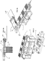
- the chip holder cover 20 may for instance be hingeably coupled to the base 18 and pivotable from an open position as illustrated in figure 5 to a closed position as illustrated in figures 5a to 5c .
- the microfluidic chip 2 In the open position, the microfluidic chip 2 may be positioned on the base 18 and the cover closed down thereagainst and locked with a closing mechanism 22, for instance in the form of a rotatable latch.
- clamping and closing mechanisms may be provided without departing from the scope of the invention, for instance by means of a cantilever elastic beam with a latching shoulder, a bridging element that pivots and spans over the end of the cover, a screw or bolt mechanism and various other per se well known closing and clamping mechanisms.
- the reservoir side fluidic couplings 26 in a form of hollow tubes may be secured to the base 18 and present chip coupling sections 28a projecting above the base 18 for insertion in complementary reservoir side coupling orifices 54b extending into the base 50a of the microfluidic chip 2.
- the chip coupling sections 26a of the hollow tubes 26b insert into the corresponding cavities 54b with a tight fit in order to provide a hermetic sealing between the tubes and orifice walls.
- the chip coupling section 26a of the tubes may be provided with a sealing ring or sealing coating around the tube for providing a seal between the orifice walls and tube.
- Other materials, such as an adhesive or bonding material, may also be provided.
- the chip coupling section 26a of the hollow tubes 26 may also be welded to the chip, for instance by ultrasonic welding.
- the reservoir side fluidic couplings 26 in the form of hollow tubes may be pre-mounted to the microfluidic chip 2 and permanently welded, bonded or attached thereto and disposed of with the microfluidic chip.
- the reservoir side fluidic couplings 26 in the form of hollow tubes may be fixed permanently to the microfluidic chip holder 3 and reusable for a plurality of operations with different microfluidic chips.
- the microfluidic chip holder 3 may be a component that is also single use and disposed off after the end of the operations with the microfluidic chip.
- the chip holder 3 further comprises a pump side fluidic coupling 24 for fluidically interconnecting the microfluidic chip 2 to fluidic tubes 36 connected to the valve system V, pump P and reagent and waste containers 34.
- the pump side fluidic coupling 24 may advantageously comprise hollow tubes having a chip coupling section 24a at one end that insert into pump side coupling orifices 54a of the microfluidic chip, and extending at the other end to a connector coupling section 24b for insertion into a plug coupling portion 32 of a fluidic tubes connector 4.
- the pump side fluidic coupling 24 may for instance comprise an elbow or L-shaped hollow metallic tube embedded in the base 18 of the chip holder 3 or may comprise two separate sections of tubes, one forming the chip coupling section 24a and the other forming the connector coupling section 24b interconnected fluidically by a channel formed within the base 18.
- Other couplings may also be used, for instance the tubes 24b may be removed and the connection ensured by flexible sealing rings or a gasket at the interface of the connector coupling section.
- the pump side fluidic couplings 24 may comprise an external sealing element or may be welded to the microfluidic chip or coupled by various other means in a hermetically sealed manner.
- microfluidic channels 54 fluidically interconnect the pump side coupling orifice 54a to the reservoir side coupling orifice 54b extending through a plurality of successively arranged microfluidic culture chambers 52.
- there are sixteen substantially parallel microfluidic channels 54 each channel passing through eight successively arranged culture chambers 52 such there are in total a hundred and twenty eight microfluidic chambers that may be observed with a single microfluidic chip.
- the reservoir side coupling orifices 54b of the microfluidic chip and corresponding hollow tubes 26 may advantageously be arranged in a spaced out manner in both X and Y orthogonal directions of a horizontal plane, such that the hollow tubes are spaced out according to a two-dimensional grid, the hollow tubes for instance being arranged at intersections of a substantially square or rectangular grid as best illustrated in figure 5e .
- the microfluidic channels 54 may contain worms of the same type and of similar age, fed with substantially identical nutrients. This may allow the observation of worms in a plurality of microfluidic chambers for a statistical evaluation of their behavior, growth and other phenotypes. This may be multiplied further by having similar conditions for each of the plurality of microfluidic chips 2 contained in the worm culture and observation apparatus 1. However, the conditions regarding the age of the worms, the types of nutrients, the substances injected, and the reagents used may be varied on a chip-to chip basis or on a channel-to-channel basis within a chip 2, or with certain sets of channels, and so on.
- the plurality of channels 54 of a chip having microscopic worms without substances to be tested may also be the same substance being fed into different channels 54 or microfluidic chips 2, but at different concentrations. It may be noted that co-cultures of two or more different biological models are also possible in each channel, e.g. different cell types or different types of worms and/or bacteria etc. in the same channel.
- the microfluidic chip 2 and chip holder 3 may be conveniently interconnected to the valve and pump system V, P, and the reagent and waste containers 34 with the fluidic tubes connector 4,
- the fluidic tubes connector 4 comprises a plug coupling portion 32 with orifices for hermetic coupling to the chip coupling sections 24a of the chip holder 3 and microfluidic chip 2.
- the fluidic tubes connector 4 may comprise a bottom part 28b comprising a plurality of grooves 30 to receive fluidic tubes 36 therein, and a top part 28a that covers the bottom part and clamps the ends of the fluidic tubes 36 therein.
- the top part and bottom part may be made of various materials and the clamping together may be made in a removable or permanent manner, for instance by screws or by bounding or welding.
- the fluidic tubes 36 are preferably in the form of, or at least comprises a portion of, supple polymer tubes that may be squeezed in a peristaltic type or shuttle type of pump.
- the fluidic tubes 36 may thus extend from the fluidic tubes connector 4 all the way to the valve system V.
- the pump P may be in the form of a peristaltic pump or a shuttle type pump engaging fluidic tubes extending between reagent containers 34 and the valve system V.
- the configuration of the pump P and valve V may take various forms, for instance the pump may be positioned between the valve system V and the microfluidic chip 2, or a separate independently controlled pump may be provided between the valve system and chips.
- a peristaltic pump system a syringe pump system or a membrane type pump system may be provided.
- Such pump systems are per se known and do not need to be further described, as are valve systems.
- the support structure 10 of the worm culture and observation apparatus 1 may further comprise a tube tip sealing plate 9 that is movably mounted on the support structure and that may be positioned with an actuation mechanism or alternatively may be provided as a plate that is manually insertable, below the tips 26b of the hollow tubes 26.
- the tube tip sealing plate 9 comprises a support frame 11 and one or more elastomer pads 13 against which the tips 26b of the hollow tubes 26 may be pressed.
- the tube tip sealing plate 9 is used during a priming operation of the worm culture and observation apparatus 1 to seal the tips 26b of the rigid tubes 26 in order to apply pressure within the microfluidic channels 54.
- the pressure within the microfluidic chip channels and within the fluidic tubes 36 may in particular be advantageously used during a debubbling operation.
- the tube tip sealing plate 9 may also be employed during other steps requiring a certain overpressure to be created in the microfluidic channels.
- the one or more microfluidic chips are mounted in the corresponding chip holders 3 fluidically coupled to corresponding fluidic tubes connectors 4.
- the pump P is operated to draw liquid from a reagent's container 34, constituting in particular a priming liquid such as an aqueous solution such as DI water, ethanol 70% or directly S-medium (a per se typical medium used for worm liquid culture and maintenance) for filling the fluidic tube 36, microfluidics channels 54, and hollow tubes 26 with the priming liquid, thus removing the air out of the fluidic channel system.
- a priming liquid such as an aqueous solution such as DI water, ethanol 70% or directly S-medium (a per se typical medium used for worm liquid culture and maintenance) for filling the fluidic tube 36, microfluidics channels 54, and hollow tubes 26 with the priming liquid, thus removing the air out of the fluidic channel system.
- worms may be loaded into the culture chambers 52 of the microfluidic chips 2. This may be performed for instance by placing worms in an early stage of development, at a size sufficiently small to be pumped into the microfluidic chambers 52, in liquid in the nutrient reservoirs 5 that are positioned under the hollow tubes, immersing the hollow tubes within the nutrient reservoirs and operating the pump in the opposite direction to the priming direction.
- the valve system V may be actuated to direct the pump liquid into a waste container, considering that some of the worms will be pumped through all of the culture chambers 52 and into the fluidic tubes 36.
- the nutrient reservoirs 5 may then be removed once the worms have been loaded in the microfluidic chip and a slight forward pumping effected to ensure that droplets are formed at the tips 26b of the hollow tubes 26. This ensures that the tubes are filled completely with liquid, that there is no air inside, when subsequently inserting the tips into nutrient reservoirs 5 containing nutrients and the substances to be tested. These substances may then be drawn into the microfluidic channels and chambers 54, 52 of the microfluidic chips 2 by operation of the pump in the reverse direction to the priming direction.
- the temperature and possibly other environmental conditions may advantageously be controlled within the enclosure chamber to promote optimal growth of the worms for the testing period with limited manual intervention. Also, if required, temperature cycles may be automatically performed to test temperature related factors on the microscopic worm if required by the testing protocol.
- the microscope 44 may be positioned sequentially over various microfluidic chips 2 for capturing still or moving images, and there may also be a plurality of microscopes provided on the system for capturing images of the microfluidic chambers and worms therein simultaneously.
Landscapes
- Health & Medical Sciences (AREA)
- Chemical & Material Sciences (AREA)
- Life Sciences & Earth Sciences (AREA)
- Engineering & Computer Science (AREA)
- Organic Chemistry (AREA)
- Bioinformatics & Cheminformatics (AREA)
- Zoology (AREA)
- Wood Science & Technology (AREA)
- Biomedical Technology (AREA)
- Biotechnology (AREA)
- Microbiology (AREA)
- Biochemistry (AREA)
- General Health & Medical Sciences (AREA)
- General Engineering & Computer Science (AREA)
- Genetics & Genomics (AREA)
- Sustainable Development (AREA)
- Analytical Chemistry (AREA)
- Immunology (AREA)
- Molecular Biology (AREA)
- Cell Biology (AREA)
- Toxicology (AREA)
- Physics & Mathematics (AREA)
- Urology & Nephrology (AREA)
- Hematology (AREA)
- Clinical Laboratory Science (AREA)
- Proteomics, Peptides & Aminoacids (AREA)
- Tropical Medicine & Parasitology (AREA)
- Food Science & Technology (AREA)
- Medicinal Chemistry (AREA)
- General Physics & Mathematics (AREA)
- Pathology (AREA)
- Computer Hardware Design (AREA)
- Biophysics (AREA)
- Dispersion Chemistry (AREA)
- Thermal Sciences (AREA)
- Apparatus Associated With Microorganisms And Enzymes (AREA)
Claims (18)
- Mikroskopische Wurmkultur und Beobachtungsvorrichtung (1), die eine Tragstruktur (10), einen oder mehrere Chip-Halter (3), die an der Tragstruktur montiert sind, eine Pumpe (P) und ein Ventilsystem (V) umfasst, wobei jeder Chip-Halter zum Halten eines Mikrofluidik-Chips (2) ausgestaltet ist, der einen oder mehrere Mikrofluidik-Kanäle (54) und Kulturkammern (52) darin aufweist, die sich zwischen einer pumpenseitigen Kopplung (44a) des Mikrofluidik-Chips und einer behälterseitigen Kopplung (44b) des Mikrofluidik-Chips erstrecken, wobei die Tragstruktur eine Behältertragplattform (7) umfasst, die an einem beweglichen Tisch (12) montiert ist, wobei die Behältertragplattform (7) dazu ausgestaltet ist, eine Vielzahl von Nahrungsbehältern (5) zum Enthalten von mikroskopischen Würmern oder Nährstoffen und zu testenden Substanzen in einer Flüssigkeit zu halten, wobei der Chip-Halter (3) und/oder die Mikrofluidik-Chips (2) behälterseitige Fluidikkopplungen (26) in der Form hohler Schläuche umfassen, die sich von dem Mikrofluidik-Chip (2) zu einer Spitze (26b) an einem freien Ende des hohlen Schlauchs erstrecken, wobei jede Spitze (26b) in einen entsprechenden Nahrungsbehälter (5) einführbar ist, wobei die Tragstruktur eine Umhüllung (15), die eine Kammer bildet, in welcher der eine oder die mehreren Chip-Halter und die Behältertragplattform untergebracht sind, und eine Temperaturregelungseinheit (19) und einen Temperatursensor (23) zum Regeln der Temperatur innerhalb der Kammer umfasst, wobei die Umhüllung eine öffenbare oder abnehmbare Abdeckung (17) umfasst, die Zugang zum Inneren der Umhüllung erlaubt, und wobei der bewegliche Tisch an einen Schwingmechanismus gekoppelt ist, der dazu ausgestaltet ist, die Behältertragplattform (7) in einer horizontalen Ebene mit einer Amplitude zu schwingen, die kleiner als ein Durchmesser (D) des Nahrungsbehälters (5) ist.
- Vorrichtung nach dem vorhergehenden Anspruch, wobei der bewegliche Tisch an einen Höhenbetätigungsorganmechanismus (14) zum Betätigen einer vertikalen Bewegung der Behältertragplattform mit dem Höhenbetätigungsorganmechanismus gekoppelt ist.
- Vorrichtung nach einem der vorhergehenden Ansprüche, wobei eine Vielzahl der Chip-Halter vorhanden sind, die im Wesentlichen parallel an der Tragstruktur angeordnet sind.
- Vorrichtung nach einem der vorhergehenden Ansprüche in Verbindung mit den Mikrofluidik-Chips (2), wobei jeder Mikrofluidik-Chip eine Vielzahl von parallelen Mikrofluidik-Kanälen (54) umfasst, wobei jeder Mikrofluidik-Kanal eine Vielzahl von aufeinanderfolgenden Kulturkammern (52) fluidisch durchquert.
- Vorrichtung nach dem vorhergehenden Anspruch, wobei jeder Mikrofluidik-Kanal (54) eine pumpenseitige Kopplungsöffnung (54a) und eine behälterseitige Kopplungsöffnung (54b) umfasst, wobei die Öffnungen dazu ausgestaltet sind, Enden von hohlen Schläuchen auf eine dichtende Weise einführbar aufzunehmen.
- Vorrichtung nach einem der vorhergehenden Ansprüche, wobei die Mikrofluidik-Chips fluidisch an entsprechende Fluidikschlauchverbinder (4) gekoppelt sind, die steckbar an den Chip-Halter (3) gekoppelt sind und Enden von Fluidikschläuchen (36) dichtend aufnehmen, der sich zum Pumpen- und/oder Ventilsystem erstrecken.
- Vorrichtung nach einem der vorhergehenden Ansprüche, ferner umfassend eine Schlauchspitzen-Dichtungsplatte (9), die einen Tragrahmen (11) und eine Elastomerunterlage (13) umfasst, die unter den Spitzen (26b) der hohlen Schläuche beweglich ist und dazu ausgestaltet ist, die Elastomerunterlagen (13) während eines entsprechenden Betriebsschritts der Vorrichtung dichtend gegen die Spitzen zu drücken.
- Vorrichtung nach dem vorhergehenden Anspruch, wobei der entsprechende Betriebsschritt einen Vorgang zum Entblasen der Fluidikkanäle innerhalb des Mikrofluidik-Chips umfasst.
- Vorrichtung nach einem der vorhergehenden Ansprüche, wobei die behälterseitigen Kopplungsöffnungen (54b) des Mikrofluidik-Chips und entsprechende hohle Schläuche (26) in einer beabstandeten Weise in sowohl der orthogonalen X- als auch Y-Richtung einer horizontalen Ebene angeordnet sind, derart dass die hohlen Schläuche gemäß einem zweidimensionalen Raster beabstandet sind, wobei die hohlen Schläuche an Schnittpunkten eines im Wesentlichen quadratischen oder rechteckigen Rasters angeordnet sind.
- Vorrichtung nach einem der vorhergehenden Ansprüche, wobei die pumpenseitige Fluidikkopplung (24) eine Vielzahl von hohlen Schläuchen umfasst, die an den Chip-Halter (3) gekoppelt sind und in entsprechende pumpenseitige Kopplungsöffnungen (54a) des Mikrofluidik-Chips (2) eingeführt sind.
- Vorrichtung nach einem der vorhergehenden Ansprüche, wobei der Chip-Halter eine Basis (18) und eine Abdeckung (20) umfasst, die schwenkbar an die Basis gekoppelt ist, von einer offenen Position beweglich ist, in welcher der Mikrofluidik-Chip (2) an der Basis (18) untergebracht sein kann, und zu einer geschlossenen Position beweglich ist, die von einem Schließmechanismus (22) gehalten wird, der den Mikrofluidik-Chip innerhalb des Chip-Halters klemmt.
- Vorrichtung nach einem der vorhergehenden Ansprüche, wobei der Chip-Halter ein Sichtfenster (21) in sowohl einer Basis (18) als auch einer Abdeckung (20) umfasst, um es Licht zu erlauben, durch einen Boden des Mikrofluidik-Chips zu einer oberen Seite zu scheinen, die von einem Mikroskop (44) sichtbar ist.
- Vorrichtung nach einem der vorhergehenden Ansprüche, wobei ein Bildgebungssystem (42, 44), das ein Mikroskop (44), ein Beleuchtungssystem (38) und ein Rechensystem (46) umfasst, das mit dem Ventilsystem (V) und der Pumpe (P), einem Betätigungsmechanismus (14, 16), einem Beleuchtungssystem (38) und einem Bildgebungssystem (42, 44) verbunden ist, zum automatischen Betrieb mikroskopischer Würmer in den Kulturkammern (52) des Mikrofluidik-Chips (2) und Abbilden der mikroskopischen Würmer in den Kulturkammern über einen Zeitraum ausgestaltet ist, der in einem Bereich von einigen wenigen Tagen bis zu einigen wenigen Wochen reicht.
- Verfahren zum Betrieb einer mikroskopischen Wurmkultur und Beobachtungsvorrichtung (1) nach einem der vorhergehenden Ansprüche, das einen Wurmzufuhrvorgang umfasst, der das Betätigen der Pumpe (P) in einer Zufuhrrichtung zum Saugen von Flüssigkeit von den Nahrungsbehältern (5) in die Kulturkammern (52) der Mikrofluidik-Chips und Rühren der Flüssigkeit in den Nahrungsbehältern (5) durch Betätigung der Schwingbewegung und der Höhenverstellungsbewegung der Behältertragplattform (7) entweder gleichzeitig während des Betriebs der Pumpe oder unmittelbar vor dem Betrieb der Pumpe umfasst.
- Verfahren nach dem vorhergehenden Anspruch, wobei der Betrieb der Vorrichtung einen Chip-Vorfüllschritt nach dem Laden eines neuen Mikrofluidik-Chips in die Vorrichtung umfasst, wobei der Chip-Vorfüllschritt das Betreiben der Pumpe in einer Richtung von Fluidströmung umfasst, die aus den hohlen Schläuchen austritt (einer Vorfüllrichtung), um eine Vorfüllflüssigkeit durch die Mikrofluidik-Kanäle (54) und Kulturkammern (52) der Mikrofluidik-Chips zu pumpen, bis die Vorfüllflüssigkeit aus Spitzen (26b) der hohlen Schläuche (26) austritt.
- Verfahren nach einem der vorhergehenden Ansprüche, wobei der Betrieb der Vorrichtung einen Chip-Entblasvorgang umfasst, wobei der Entblasvorgang das Pumpen einer Flüssigkeit in einer Vorfüllrichtung bei Drücken einer Elastomerunterlage (13) gegen die Spitzen umfasst, um sie dichtend zu schließen und einen Überdruck innerhalb der Mikrofluidik-Kanäle zu erzeugen.
- Verfahren nach einem der vorhergehenden Ansprüche, wobei der Betrieb der Vorrichtung ein Vorgang zum Laden von Würmern auf einen Chip umfasst, der das Positionieren von Nahrungsbehältern, die mikroskopische Würmer enthalten, die in Kulturkammern (52) der Mikrofluidik-Chips (2) in Nahrungsbehältern (5) einzuspritzen sind, das Platzieren der Nahrungsbehälter unter den Spitzen der hohlen Schläuche und das Einführen der Spitzen in die Flüssigkeit und den Betrieb der Pumpe mit Impulsen umfasst, um mikroskopische Würmer in die Kulturkammern (52) einzuspritzen.
- Verfahren nach einem der vorhergehenden Ansprüche, wobei der Betrieb der Vorrichtung einen Behälteraustauschschritt umfasst, der das Entfernen der Spitzen der hohlen Schläuche aus der ersten Menge von Behältern, das Betreiben der Pumpe in einer Vorfüllrichtung, um Tropfen an den Spitzen zu erzeugen, und das anschließende Bewegen der Behältertragplattform (7) zum Einführen der Spitzen der hohlen Schläuche in eine neue Menge von Nahrungsbehältern (5) umfasst.
Applications Claiming Priority (2)
| Application Number | Priority Date | Filing Date | Title |
|---|---|---|---|
| EP21191741.4A EP4137558A1 (de) | 2021-08-17 | 2021-08-17 | Vorrichtung zur mikroskopischen wurmbeobachtung |
| PCT/EP2022/072867 WO2023021038A1 (en) | 2021-08-17 | 2022-08-16 | Apparatus for microscopic worm observation |
Publications (3)
| Publication Number | Publication Date |
|---|---|
| EP4388075A1 EP4388075A1 (de) | 2024-06-26 |
| EP4388075C0 EP4388075C0 (de) | 2025-05-21 |
| EP4388075B1 true EP4388075B1 (de) | 2025-05-21 |
Family
ID=77367369
Family Applications (2)
| Application Number | Title | Priority Date | Filing Date |
|---|---|---|---|
| EP21191741.4A Withdrawn EP4137558A1 (de) | 2021-08-17 | 2021-08-17 | Vorrichtung zur mikroskopischen wurmbeobachtung |
| EP22764796.3A Active EP4388075B1 (de) | 2021-08-17 | 2022-08-16 | Vorrichtung zur mikroskopischen wurmbeobachtung |
Family Applications Before (1)
| Application Number | Title | Priority Date | Filing Date |
|---|---|---|---|
| EP21191741.4A Withdrawn EP4137558A1 (de) | 2021-08-17 | 2021-08-17 | Vorrichtung zur mikroskopischen wurmbeobachtung |
Country Status (5)
| Country | Link |
|---|---|
| US (1) | US12516366B2 (de) |
| EP (2) | EP4137558A1 (de) |
| JP (1) | JP7646266B2 (de) |
| ES (1) | ES3037737T3 (de) |
| WO (1) | WO2023021038A1 (de) |
Family Cites Families (8)
| Publication number | Priority date | Publication date | Assignee | Title |
|---|---|---|---|---|
| AU2010256429B2 (en) * | 2009-06-05 | 2015-09-17 | Integenx Inc. | Universal sample preparation system and use in an integrated analysis system |
| SG11201402558QA (en) | 2011-12-03 | 2014-06-27 | Emd Millipore Corp | Micro-incubation systems for microfluidic cell culture and methods |
| ES2795991T3 (es) | 2014-10-20 | 2020-11-25 | Ecole Polytechnique Fed Lausanne Epfl | Dispositivo microfluídico, sistema y procedimiento para el estudio de organismos |
| US10065985B2 (en) * | 2015-02-03 | 2018-09-04 | The Regents Of The University Of California | Method for fully automated synthesis of 16β-18F-fluoro-5α-dihydrotestosterone (18F-FDHT) |
| KR101811786B1 (ko) * | 2015-05-14 | 2017-12-22 | 바디텍메드(주) | 일체화된 반응 및 검출 수단을 구비한 시험 장치에 사용되는 스테이션 |
| WO2017027838A1 (en) | 2015-08-13 | 2017-02-16 | President And Fellows Of Harvard College | Microfluidic devices and systems for cell culture and/or assay |
| US10184104B2 (en) | 2015-11-19 | 2019-01-22 | Alexander Lee Lianides | Automated system for cultivating transgenic C. elegans |
| CN105543085B (zh) * | 2016-02-15 | 2017-07-18 | 江苏大学 | 用于微生物肥菌培养条件优化控制的微流控装置和方法 |
-
2021
- 2021-08-17 EP EP21191741.4A patent/EP4137558A1/de not_active Withdrawn
-
2022
- 2022-08-16 ES ES22764796T patent/ES3037737T3/es active Active
- 2022-08-16 JP JP2024510355A patent/JP7646266B2/ja active Active
- 2022-08-16 EP EP22764796.3A patent/EP4388075B1/de active Active
- 2022-08-16 WO PCT/EP2022/072867 patent/WO2023021038A1/en not_active Ceased
- 2022-08-16 US US18/683,730 patent/US12516366B2/en active Active
Also Published As
| Publication number | Publication date |
|---|---|
| JP7646266B2 (ja) | 2025-03-17 |
| US12516366B2 (en) | 2026-01-06 |
| US20240263213A1 (en) | 2024-08-08 |
| EP4388075C0 (de) | 2025-05-21 |
| JP2024532855A (ja) | 2024-09-10 |
| ES3037737T3 (en) | 2025-10-06 |
| EP4137558A1 (de) | 2023-02-22 |
| EP4388075A1 (de) | 2024-06-26 |
| WO2023021038A1 (en) | 2023-02-23 |
Similar Documents
| Publication | Publication Date | Title |
|---|---|---|
| US12066373B2 (en) | System and method for retrieving and analyzing particles | |
| US20250187001A1 (en) | Fluidic autosampler and incubator | |
| US20100300563A1 (en) | Modular device and method for moving fluids to and from a sample delivery element | |
| RU2672883C2 (ru) | Картридж формирования изображения, пипетка и способ их применения для прямой микроскопии препарата мокроты | |
| JP2021181992A (ja) | 自動化標本堆積システム及び関連する方法 | |
| Lagoy et al. | Microfluidic devices for behavioral analysis, microscopy, and neuronal imaging in Caenorhabditis elegans | |
| US12516366B2 (en) | Apparatus for microscopic worm observation | |
| US20210231567A1 (en) | Device and methods for optically characterizing fluids and/or objects enclosed therein in microchannels | |
| US12553017B2 (en) | Apparatus for microscopic biolocigal organism observation | |
| EP1693670A1 (de) | Reaktionsgefäss und reaktionsvorrichtung damit, nachweisvorrichtung sowie verfahren zur herstellung des reaktionsgefässes | |
| JPH08114601A (ja) | 液体検体の多項目検査分析装置 | |
| EP4205852A1 (de) | System und verfahren zum rückgewinnen und analysieren von teilchen | |
| WO2010077784A1 (en) | Test cartridges for flow assays and methods for their use | |
| Lagoy et al. | Microfluidic devices for behavioral analysis, microscopy, and neuronal imaging in Caenorhabditis elegans | |
| US10591501B2 (en) | Automatic structure determination | |
| CA3203372A1 (en) | Chemical processing system, instrument and sample cartridge | |
| Artmann et al. | Single Action Push to Tilt Mechanism for Cell Culture Media Change within Incubators for Screw Cap Flasks | |
| NL2026640B1 (en) | System and method for loading a microfluidic chip | |
| US20250130157A1 (en) | Device and method to be carried out for examining and/or processing an in particular biological or medical sample | |
| KR102606708B1 (ko) | 미세조류이미지 연속 측정장치를 위한 전처리장치 | |
| US20250291169A1 (en) | Microscope stage and method for examining a sample | |
| WO2026039622A1 (en) | Systems and methods for nanopore sequencing | |
| CN118562616A (zh) | 细胞培养系统 |
Legal Events
| Date | Code | Title | Description |
|---|---|---|---|
| STAA | Information on the status of an ep patent application or granted ep patent |
Free format text: STATUS: UNKNOWN |
|
| STAA | Information on the status of an ep patent application or granted ep patent |
Free format text: STATUS: THE INTERNATIONAL PUBLICATION HAS BEEN MADE |
|
| PUAI | Public reference made under article 153(3) epc to a published international application that has entered the european phase |
Free format text: ORIGINAL CODE: 0009012 |
|
| STAA | Information on the status of an ep patent application or granted ep patent |
Free format text: STATUS: REQUEST FOR EXAMINATION WAS MADE |
|
| 17P | Request for examination filed |
Effective date: 20240306 |
|
| AK | Designated contracting states |
Kind code of ref document: A1 Designated state(s): AL AT BE BG CH CY CZ DE DK EE ES FI FR GB GR HR HU IE IS IT LI LT LU LV MC MK MT NL NO PL PT RO RS SE SI SK SM TR |
|
| DAV | Request for validation of the european patent (deleted) | ||
| DAX | Request for extension of the european patent (deleted) | ||
| GRAP | Despatch of communication of intention to grant a patent |
Free format text: ORIGINAL CODE: EPIDOSNIGR1 |
|
| STAA | Information on the status of an ep patent application or granted ep patent |
Free format text: STATUS: GRANT OF PATENT IS INTENDED |
|
| INTG | Intention to grant announced |
Effective date: 20241216 |
|
| GRAS | Grant fee paid |
Free format text: ORIGINAL CODE: EPIDOSNIGR3 |
|
| GRAA | (expected) grant |
Free format text: ORIGINAL CODE: 0009210 |
|
| STAA | Information on the status of an ep patent application or granted ep patent |
Free format text: STATUS: THE PATENT HAS BEEN GRANTED |
|
| AK | Designated contracting states |
Kind code of ref document: B1 Designated state(s): AL AT BE BG CH CY CZ DE DK EE ES FI FR GB GR HR HU IE IS IT LI LT LU LV MC MK MT NL NO PL PT RO RS SE SI SK SM TR |
|
| REG | Reference to a national code |
Ref country code: GB Ref legal event code: FG4D |
|
| REG | Reference to a national code |
Ref country code: CH Ref legal event code: EP |
|
| REG | Reference to a national code |
Ref country code: DE Ref legal event code: R096 Ref document number: 602022015018 Country of ref document: DE |
|
| REG | Reference to a national code |
Ref country code: IE Ref legal event code: FG4D |
|
| U01 | Request for unitary effect filed |
Effective date: 20250617 |
|
| U07 | Unitary effect registered |
Designated state(s): AT BE BG DE DK EE FI FR IT LT LU LV MT NL PT RO SE SI Effective date: 20250709 |
|
| U20 | Renewal fee for the european patent with unitary effect paid |
Year of fee payment: 4 Effective date: 20250722 |
|
| REG | Reference to a national code |
Ref country code: ES Ref legal event code: FG2A Ref document number: 3037737 Country of ref document: ES Kind code of ref document: T3 Effective date: 20251006 |
|
| PGFP | Annual fee paid to national office [announced via postgrant information from national office to epo] |
Ref country code: ES Payment date: 20250926 Year of fee payment: 4 |
|
| PG25 | Lapsed in a contracting state [announced via postgrant information from national office to epo] |
Ref country code: GR Free format text: LAPSE BECAUSE OF FAILURE TO SUBMIT A TRANSLATION OF THE DESCRIPTION OR TO PAY THE FEE WITHIN THE PRESCRIBED TIME-LIMIT Effective date: 20250822 Ref country code: NO Free format text: LAPSE BECAUSE OF FAILURE TO SUBMIT A TRANSLATION OF THE DESCRIPTION OR TO PAY THE FEE WITHIN THE PRESCRIBED TIME-LIMIT Effective date: 20250821 |
|
| PG25 | Lapsed in a contracting state [announced via postgrant information from national office to epo] |
Ref country code: PL Free format text: LAPSE BECAUSE OF FAILURE TO SUBMIT A TRANSLATION OF THE DESCRIPTION OR TO PAY THE FEE WITHIN THE PRESCRIBED TIME-LIMIT Effective date: 20250521 |
|
| PG25 | Lapsed in a contracting state [announced via postgrant information from national office to epo] |
Ref country code: HR Free format text: LAPSE BECAUSE OF FAILURE TO SUBMIT A TRANSLATION OF THE DESCRIPTION OR TO PAY THE FEE WITHIN THE PRESCRIBED TIME-LIMIT Effective date: 20250521 |
|
| PGFP | Annual fee paid to national office [announced via postgrant information from national office to epo] |
Ref country code: CH Payment date: 20250901 Year of fee payment: 4 |
|
| PG25 | Lapsed in a contracting state [announced via postgrant information from national office to epo] |
Ref country code: RS Free format text: LAPSE BECAUSE OF FAILURE TO SUBMIT A TRANSLATION OF THE DESCRIPTION OR TO PAY THE FEE WITHIN THE PRESCRIBED TIME-LIMIT Effective date: 20250821 |
|
| PG25 | Lapsed in a contracting state [announced via postgrant information from national office to epo] |
Ref country code: IS Free format text: LAPSE BECAUSE OF FAILURE TO SUBMIT A TRANSLATION OF THE DESCRIPTION OR TO PAY THE FEE WITHIN THE PRESCRIBED TIME-LIMIT Effective date: 20250921 |
|
| PG25 | Lapsed in a contracting state [announced via postgrant information from national office to epo] |
Ref country code: SM Free format text: LAPSE BECAUSE OF FAILURE TO SUBMIT A TRANSLATION OF THE DESCRIPTION OR TO PAY THE FEE WITHIN THE PRESCRIBED TIME-LIMIT Effective date: 20250521 |
|
| PG25 | Lapsed in a contracting state [announced via postgrant information from national office to epo] |
Ref country code: CZ Free format text: LAPSE BECAUSE OF FAILURE TO SUBMIT A TRANSLATION OF THE DESCRIPTION OR TO PAY THE FEE WITHIN THE PRESCRIBED TIME-LIMIT Effective date: 20250521 |
|
| PG25 | Lapsed in a contracting state [announced via postgrant information from national office to epo] |
Ref country code: SK Free format text: LAPSE BECAUSE OF FAILURE TO SUBMIT A TRANSLATION OF THE DESCRIPTION OR TO PAY THE FEE WITHIN THE PRESCRIBED TIME-LIMIT Effective date: 20250521 |
|
| PLBE | No opposition filed within time limit |
Free format text: ORIGINAL CODE: 0009261 |
|
| STAA | Information on the status of an ep patent application or granted ep patent |
Free format text: STATUS: NO OPPOSITION FILED WITHIN TIME LIMIT |
|
| PG25 | Lapsed in a contracting state [announced via postgrant information from national office to epo] |
Ref country code: MC Free format text: LAPSE BECAUSE OF FAILURE TO SUBMIT A TRANSLATION OF THE DESCRIPTION OR TO PAY THE FEE WITHIN THE PRESCRIBED TIME-LIMIT Effective date: 20250521 |
|
| REG | Reference to a national code |
Ref country code: CH Ref legal event code: L10 Free format text: ST27 STATUS EVENT CODE: U-0-0-L10-L00 (AS PROVIDED BY THE NATIONAL OFFICE) Effective date: 20260402 |
|
| 26N | No opposition filed |
Effective date: 20260224 |