EP4388204B1 - Kühlvorrichtung mit einem lüfter und gehäuse mit einer solchen kühlvorrichtung - Google Patents
Kühlvorrichtung mit einem lüfter und gehäuse mit einer solchen kühlvorrichtung Download PDFInfo
- Publication number
- EP4388204B1 EP4388204B1 EP23732954.5A EP23732954A EP4388204B1 EP 4388204 B1 EP4388204 B1 EP 4388204B1 EP 23732954 A EP23732954 A EP 23732954A EP 4388204 B1 EP4388204 B1 EP 4388204B1
- Authority
- EP
- European Patent Office
- Prior art keywords
- fan
- housing
- cooling device
- motor housing
- heat sink
- Prior art date
- Legal status (The legal status is an assumption and is not a legal conclusion. Google has not performed a legal analysis and makes no representation as to the accuracy of the status listed.)
- Active
Links
Images




Classifications
-
- F—MECHANICAL ENGINEERING; LIGHTING; HEATING; WEAPONS; BLASTING
- F04—POSITIVE - DISPLACEMENT MACHINES FOR LIQUIDS; PUMPS FOR LIQUIDS OR ELASTIC FLUIDS
- F04D—NON-POSITIVE-DISPLACEMENT PUMPS
- F04D25/00—Pumping installations or systems
- F04D25/02—Units comprising pumps and their driving means
- F04D25/06—Units comprising pumps and their driving means the pump being electrically driven
- F04D25/0606—Units comprising pumps and their driving means the pump being electrically driven the electric motor being specially adapted for integration in the pump
- F04D25/0613—Units comprising pumps and their driving means the pump being electrically driven the electric motor being specially adapted for integration in the pump the electric motor being of the inside-out type, i.e. the rotor is arranged radially outside a central stator
-
- F—MECHANICAL ENGINEERING; LIGHTING; HEATING; WEAPONS; BLASTING
- F04—POSITIVE - DISPLACEMENT MACHINES FOR LIQUIDS; PUMPS FOR LIQUIDS OR ELASTIC FLUIDS
- F04D—NON-POSITIVE-DISPLACEMENT PUMPS
- F04D25/00—Pumping installations or systems
- F04D25/02—Units comprising pumps and their driving means
- F04D25/06—Units comprising pumps and their driving means the pump being electrically driven
- F04D25/0693—Details or arrangements of the wiring
-
- F—MECHANICAL ENGINEERING; LIGHTING; HEATING; WEAPONS; BLASTING
- F04—POSITIVE - DISPLACEMENT MACHINES FOR LIQUIDS; PUMPS FOR LIQUIDS OR ELASTIC FLUIDS
- F04D—NON-POSITIVE-DISPLACEMENT PUMPS
- F04D29/00—Details, component parts, or accessories
- F04D29/08—Sealings
- F04D29/083—Sealings especially adapted for elastic fluid pumps
-
- F—MECHANICAL ENGINEERING; LIGHTING; HEATING; WEAPONS; BLASTING
- F04—POSITIVE - DISPLACEMENT MACHINES FOR LIQUIDS; PUMPS FOR LIQUIDS OR ELASTIC FLUIDS
- F04D—NON-POSITIVE-DISPLACEMENT PUMPS
- F04D29/00—Details, component parts, or accessories
- F04D29/58—Cooling; Heating; Diminishing heat transfer
- F04D29/582—Cooling; Heating; Diminishing heat transfer specially adapted for elastic fluid pumps
-
- F—MECHANICAL ENGINEERING; LIGHTING; HEATING; WEAPONS; BLASTING
- F04—POSITIVE - DISPLACEMENT MACHINES FOR LIQUIDS; PUMPS FOR LIQUIDS OR ELASTIC FLUIDS
- F04D—NON-POSITIVE-DISPLACEMENT PUMPS
- F04D29/00—Details, component parts, or accessories
- F04D29/60—Mounting; Assembling; Disassembling
- F04D29/64—Mounting; Assembling; Disassembling of axial pumps
- F04D29/644—Mounting; Assembling; Disassembling of axial pumps especially adapted for elastic fluid pumps
- F04D29/646—Mounting or removal of fans
-
- G—PHYSICS
- G06—COMPUTING OR CALCULATING; COUNTING
- G06F—ELECTRIC DIGITAL DATA PROCESSING
- G06F1/00—Details not covered by groups G06F3/00 - G06F13/00 and G06F21/00
- G06F1/16—Constructional details or arrangements
- G06F1/18—Packaging or power distribution
- G06F1/181—Enclosures
- G06F1/182—Enclosures with special features, e.g. for use in industrial environments; grounding or shielding against radio frequency interference [RFI] or electromagnetical interference [EMI]
-
- G—PHYSICS
- G06—COMPUTING OR CALCULATING; COUNTING
- G06F—ELECTRIC DIGITAL DATA PROCESSING
- G06F1/00—Details not covered by groups G06F3/00 - G06F13/00 and G06F21/00
- G06F1/16—Constructional details or arrangements
- G06F1/20—Cooling means
-
- H—ELECTRICITY
- H02—GENERATION; CONVERSION OR DISTRIBUTION OF ELECTRIC POWER
- H02K—DYNAMO-ELECTRIC MACHINES
- H02K5/00—Casings; Enclosures; Supports
- H02K5/04—Casings or enclosures characterised by the shape, form or construction thereof
- H02K5/10—Casings or enclosures characterised by the shape, form or construction thereof with arrangements for protection from ingress, e.g. water or fingers
-
- H—ELECTRICITY
- H02—GENERATION; CONVERSION OR DISTRIBUTION OF ELECTRIC POWER
- H02K—DYNAMO-ELECTRIC MACHINES
- H02K7/00—Arrangements for handling mechanical energy structurally associated with dynamo-electric machines, e.g. structural association with mechanical driving motors or auxiliary dynamo-electric machines
- H02K7/14—Structural association with mechanical loads, e.g. with hand-held machine tools or fans
-
- H—ELECTRICITY
- H05—ELECTRIC TECHNIQUES NOT OTHERWISE PROVIDED FOR
- H05K—PRINTED CIRCUITS; CASINGS OR CONSTRUCTIONAL DETAILS OF ELECTRIC APPARATUS; MANUFACTURE OF ASSEMBLAGES OF ELECTRICAL COMPONENTS
- H05K7/00—Constructional details common to different types of electric apparatus
- H05K7/20—Modifications to facilitate cooling, ventilating, or heating
- H05K7/2089—Modifications to facilitate cooling, ventilating, or heating for power electronics, e.g. for inverters for controlling motor
- H05K7/20909—Forced ventilation, e.g. on heat dissipaters coupled to components
Definitions
- the invention relates to a cooling device for cooling power electronic components arranged in a housing, with a heat sink and with a fan with an electric motor with a rotor and rotor blades connected to the rotor in a rotationally fixed manner, wherein the motor is arranged in a motor housing and is connected to a cable for supplying electrical energy, and the heat sink has a plurality of cooling fins and a recess for receiving the fan, wherein a depression is arranged in the recess of the heat sink, which is designed to receive the motor housing of the fan.
- the invention relates to a housing for accommodating power electronic components, in particular an inverter housing, with a housing front and at least one rear housing part.
- waste heat In particular, power electronic components of various electronic devices generate waste heat. Examples of such devices are inverters for photovoltaic systems, welding power sources or battery chargers. In order to ensure trouble-free operation of such devices and a long service life, efficient dissipation of waste heat is necessary. This is usually done using heat sinks in combination with fans.
- the AT 515 828 B1 a cooling device for cooling power electronic components arranged in a housing and an inverter housing with such a cooling device, which enables an improved cooling effect with a space-saving and compact design at the same time through a special arrangement of an axial fan in a recess of the heat sink with specially arranged cooling fins.
- the US 2018/0103559 A1 describes a cooling device of the type in question.
- the fan possibly together with an air guide ring to direct the cooling air, is usually attached to the heat sink or a housing part using several crossbars and screws.
- the cable for supplying the fan motor with electrical energy is usually laid along one of the crossbars.
- Such a construction is shown, for example, in the US 2010/0051232 A1 .
- the cross braces and possibly the cable generate acoustic emissions when the fan rotates.
- a helicopter rotor which generates typical helicopter noises when it passes over the helicopter's tail structure
- a conventional fan generates so-called brushing noises when it passes over the cross braces.
- additional soundproofing measures are required, which in turn can have a negative effect on the cooling of the power electronic components.
- the object of the present invention is therefore to create an above-mentioned cooling device with a fan and a housing with such a cooling device, by means of which the acoustic emissions resulting from the fan can be minimized.
- the assembly effort for the fan should be kept as low as possible. Disadvantages of known cooling devices should be avoided or at least reduced.
- the object of the invention is achieved by an above-mentioned cooling device, wherein the motor housing of the fan has a circumferential seal and the cable and a fastening element are arranged on the side of the motor housing facing away from the rotor blades, wherein a receptacle for the fastening element and a passage for the cable are arranged in the recess.
- the cooling body of the cooling device thus has a recess in the recess for the fan, into which the motor housing fits.
- the fastening element located on the motor housing is arranged in the receptacle arranged in the recess and ensures the corresponding fastening of the fan in the cooling body.
- the cable which is also arranged on the underside of the motor housing, can be used to supply the motor of the fan with electrical energy through the provided
- the cable can be threaded through the recess in the heat sink, keeping the cable away from the rotor blades where it could cause acoustic emissions when it passes over the rotor blades.
- the fan can be quickly and easily attached to the heat sink of the cooling device without cross braces or other elements that could cause brushing noises.
- the seal provided on the motor housing automatically seals it off from the heat sink. This reduces the amount of assembly and disassembly work involved.
- the fan cable does not need to be routed and sealed through other components, in particular the heat sink, to the corresponding electronic components via its own seal, and this is done on the side of the motor housing facing away from the rotor blades.
- the sealing of the power electronic components to be cooled from the environment, which is often necessary in accordance with the required protection class, is further achieved or facilitated by the circumferential seal arranged in the motor housing.
- the cooling device in question with the fan can be manufactured easily and inexpensively.
- the motor housing of the fan is essentially cylindrical. This makes it easier to create a seal with respect to the element to which the fan is mounted, for example the heat sink, and also to arrange the fan in a correspondingly designed recess in a cutout of the element, for example the heat sink, since the orientation of the fan or motor housing in relation to the recess in the heat sink is largely arbitrary. But of course, in addition to such a cylindrical design, other asymmetrical shapes of the motor housing of the fan are also conceivable.
- the seal of the motor housing of the fan can be formed by at least one O-ring arranged in a groove on the preferably cylindrical motor housing.
- the O-ring is made of a suitable elastic material, for example silicone. The seal ensures that the electronic elements are sealed from the environment when the fan is mounted, in particular on the heat sink of the cooling device.
- the seal of the motor housing of the fan can be formed by at least one lamellar seal on the cylindrical motor housing.
- the lamellar seal is made of a suitable elastic plastic. If the motor housing of the fan is made of plastic, the lamellar seal can also be integrated in a particularly suitable manner during the manufacture of the motor housing and, for example, produced in a single or multi-component injection molding process.
- the fastening element on the motor housing of the fan is preferably formed by a locking element, preferably an elastic locking pin. This allows the fan to be assembled and preferably disassembled from the element to be connected, preferably the heat sink, without tools.
- the fastening element is preferably formed by an elastic locking pin with corresponding barbs, which can be easily and quickly arranged and anchored in a hole provided for this purpose by pulling the locking pin arranged on the motor housing through the hole until the barbs engage accordingly, ensuring that the fan is held securely in the respective element, preferably the heat sink.
- the fan can be detached from the heat sink, preferably without the use of a tool.
- the fastening element can also be formed by a fastening screw. This does increase the effort involved in assembling and disassembling the fan compared to the above-mentioned locking element, as a corresponding tool, such as a screwdriver, is also required. In contrast to conventional assemblies using several fastening screws, the effort is nevertheless reduced, as only one fastening screw needs to be assembled or disassembled.
- the arrangement of the fastening screw on the motor housing ensures that the assembly of the fan does not lead to any acoustic emissions. during rotation of the rotor blades.
- the cable is arranged next to the fastening element, it can simply be arranged next to the fastening element through the appropriately designed holder for the fastening element on the element to which the fan is to be attached, in particular the heat sink. If there is a hole for the holder of the fastening element, in particular the locking pin, an additional channel for the cable can be placed next to the hole, so that a holder for the fastening element and the cable is created in the recess of the heat sink in the form of a keyhole.
- an air guide ring is provided that surrounds the rotor blades.
- Such an air guide ring which is usually cylindrical, allows the cooling air drawn in by the fan, in particular the axial fan, to be directed in a targeted manner and directed to the areas of the heat sink that are to be cooled.
- the receptacle for the fastening element is preferably formed by a hole.
- a hole can be produced particularly quickly and easily and is used to easily accommodate the fastening element formed by a locking element or a fastening screw on the motor housing.
- the cable feedthrough is also preferably formed by a hole, which can be made particularly quickly and easily.
- the cable feedthrough and the holder for the fastening element can also be made together, so that, for example, an opening for the fastening element and the cable is created in the form of a keyhole (see above).
- an above-mentioned housing for accommodating power electronic components, in particular an inverter housing, wherein an above-mentioned cooling device is provided behind the housing front, wherein an opening for sucking in ambient air is arranged in the housing front.
- a grille or other protection against contact with the fan can be arranged in the opening on the front of the housing.
- the cooling air can also be supplied at suitable points on the housing, which may mean that no grille or other protection against contact is necessary at all.
- the air guide ring of the fan is arranged or integrated in the front of the case, a simple and quick installation of the air guide ring can be achieved automatically when assembling the case.
- the air guide ring can also be formed by a separate part that is arranged around the fan in order to be able to guide the cooling air accordingly.
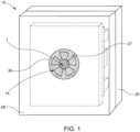
- Fig. 1 shows a schematic view of a housing 15 for accommodating power electronic components, for example an inverter housing for the inverter of a photovoltaic system.
- the housing 15 consists of a front part, the housing front 24, and a rear housing part 25. Behind the housing front 24 is a cooling device 14 (see Fig. 2 ) with a fan 1 (see Fig. 5 ).
- An opening 26 for sucking in ambient air is arranged in the housing front 24.
- a grille 27 or other contact protection is preferably provided in the opening 26.
- the position of the opening 26 is adapted accordingly to the cooling device 14 arranged behind the housing front 24.
- the fan 1 of the cooling device 14 is arranged behind the opening 26.
- the opening 26 is arranged centrally on the housing front 24.
- slots or the like can also be placed at other points on the housing front 24 for sucking in ambient air (not shown).
- the power electronic components to be cooled are arranged behind the heat sink 16 of the cooling device 14 (not shown or only indicated by the dashed lines).
- the cooling air is discharged via suitably arranged slots or the like in the housing front 24 or the rear housing part 25 (not shown).
- the housing 15 can also consist of several housing parts and have a shape other than the cuboid shape shown.
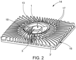
- FIG. 2 is a view of a cooling device 14 for cooling in a housing 15 (see Fig. 1 ) arranged power electronic components according to the prior art.
- the cooling device 14 includes a combination of a heat sink 16 with an integrated fan 1.
- the fan 1 is arranged in a recess 18 in the heat sink 16.
- the heat sink 16 comprises a series of cooling fins 17, which are arranged here essentially radially around the recess 18 for the fan 1. In addition to increasing the surface area, this arrangement divides the cooling air flow and thus improves the cooling effect.
- the fan 1 is preferably placed at a central point on the heat sink 16 in order to achieve an even distribution of the ambient air drawn in over the entire surface of the heat sink 16.
- an air guide ring 13 is also arranged around the fan, with a gap being formed between its lower edge and the base of the heat sink 16. This gap enables the The air flow sucked in from above can be discharged laterally between the cooling fins 17.
- the fan 1 is usually attached to the heat sink 16 via cross braces using appropriate fastening screws. If the rotor blades 3 of the fan 1 pass the cross braces during operation, disturbing acoustic emissions, so-called stroking noises, are generated, which are to be avoided or at least reduced according to the invention.
- Fig. 3 shows a view of the heat sink 16 of a cooling device 14, which is designed to accommodate a fan 1 (see Fig. 7 ) is formed.
- the heat sink 16 has a plurality of cooling fins 17 and a recess 18 for receiving the fan 1 (see Fig. 2 ).
- a recess 19 which is designed to accommodate the motor housing 4 of the fan 1.
- the recess 19 is also correspondingly cylindrical so that the motor housing 4 of the fan 1 can be accommodated and fastened therein.
- a receptacle 20 for the fastening element 7 of the fan 1 is provided in the recess 19 and a feedthrough 21 for the cable 5 of the fan 1 is also arranged.
- the receptacle 20 for the fastening element 7 is preferably formed by a cylindrical recess 22 and the feedthrough 21 for the cable 5 is formed by a bore 23. If the cylindrical recess 22 and the bore 23 are arranged directly next to one another or in a transitional manner, this results in an opening for both the fastening element 7 and the cable 5 of the fan 1 in the form of a keyhole.
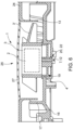
- Fig. 4 shows a sectional view through a first embodiment of a cooling device 14 according to the invention.
- the motor housing 4 of the fan 1 has a circumferential seal 6 in the form of two O-rings 9 running in a groove 8 on the motor housing 4 (see Fig. 5 , left picture).
- the cable 5 for supplying the motor 2 of the fan 1 with electrical energy and a fastening element 7 are provided on the side of the motor housing 4 facing away from the rotor blades 3'.
- This cable 5 is guided through a passage 21 in the recess 19 of the heat sink 16.
- This passage 21 is preferably formed by a bore 23 in the heat sink 16.
- the motor housing 4 is cylindrical in this embodiment.
- the recess 19 in the cutout 18 of the heat sink 16 of the cooling device 14 is also cylindrical.
- the fastening element 7 is realized by a fastening element 7 in the form of a locking element 10, preferably an elastic locking pin 11.
- the receptacle 20 for the fastening element 7 is provided in the form of a cylindrical recess 22, through which cylindrical recess 22 the elastic locking pin 11 is pulled to fasten the fan 1 to the heat sink 16. This enables the fan 1 to be attached to the heat sink 16 quickly and easily without tools.
- the elastic locking pin 11 is moved in the direction of the motor housing 4 of the fan 1 through the cylindrical recess 22 and the fan 1 is thus released from the heat sink 16.
- An air guide ring 13 surrounding the rotor blades 3' of the fan 1 serves to guide the cooling air flow.
- the air guide ring 13 can be designed as a separate part and attached to the heat sink 16 in a suitable manner, for example snapped in, or connected to the housing front 24 of the housing 15 or integrated into the housing front 24 or manufactured at the same time. In the latter case, the air guide ring 13 is automatically placed around the fan 1 when the housing 15 is closed, so that the cooling air flow can be directed accordingly.
- Fig. 5 shows a detailed view of the motor housing 4 of the fan 1 in the area of the seal 6 corresponding to the area V in Fig. 4 in two different design variants.
- the seal 6 of the motor housing 4 of the fan is formed by an O-ring 9 running in a circumferential groove 8 of the motor housing 4.
- O-rings 9 can also be arranged next to each other or one below the other in several grooves 8 in the motor housing 4 of the fan 1.
- the seal 6 is formed by at least one lamellar seal 9' on the motor housing 4.
- the lamellar seal 9' can be arranged in a groove 8 or the like in the motor housing 4 or can also be manufactured directly with the motor housing, for example in a single- or multi-component injection molding process.
- Fig. 6 a sectional view through a second embodiment of a cooling device 14 according to the invention.
- the fastening element 7 for fastening the motor housing 4 of the fan 1 to the heat sink 16 is formed by a fastening screw 12, which is screwed through the cylindrical recess 22 of the heat sink 16.
- a tool is required to attach and remove the fan 1 to or from the heat sink 16.
- Fig. 7 shows a side view of a fan 1 of the cooling device 14.
- the fan 1 has an electric motor 2 (not shown), a rotor 3 and rotor blades 3' connected to the rotor 3 in a rotationally fixed manner.
- the fan 1 also has a preferably cylindrical motor housing 4 and a cable 5 for supplying the motor 2 with electrical energy.
- the motor housing 4 has a circumferential seal 6, which is formed here by two O-rings 9.
- the cable 5 and a fastening element 7 are arranged on the side of the motor housing 4 facing away from the rotor blades 3'.
- the fastening element 7 is formed by an elastic locking pin 11.
- Fig. 8 is a bottom view of the fan 1 according to Fig. 7 shown.
- the cylindrical motor housing 4 can be seen and the cable 5 arranged on the underside or on the side facing away from the rotor blades 3' and the fastening element 7 formed as an elastic locking element 11.
- the fan 1 can be mounted particularly easily and quickly on the corresponding heat sink 16 and stroking noises caused by fastening elements or the like are avoided or at least reduced.
Landscapes
- Engineering & Computer Science (AREA)
- General Engineering & Computer Science (AREA)
- Physics & Mathematics (AREA)
- Mechanical Engineering (AREA)
- Theoretical Computer Science (AREA)
- Power Engineering (AREA)
- Microelectronics & Electronic Packaging (AREA)
- Thermal Sciences (AREA)
- Human Computer Interaction (AREA)
- General Physics & Mathematics (AREA)
- Electromagnetism (AREA)
- Computer Hardware Design (AREA)
- Cooling Or The Like Of Electrical Apparatus (AREA)
- Structures Of Non-Positive Displacement Pumps (AREA)
Description
- Die Erfindung betrifft eine Kühlvorrichtung zur Kühlung in einem Gehäuse angeordneter leistungselektronischer Komponenten, mit einem Kühlkörper und mit einem Lüfter mit einem elektrischen Motor mit einem Rotor und mit dem Rotor drehfest verbundenen Rotorblättern, wobei der Motor in einem Motorgehäuse angeordnet und mit einem Kabel zur Versorgung mit elektrischer Energie verbunden ist, und der Kühlkörper eine Vielzahl an Kühlfinnen aufweist und eine Aussparung zur Aufnahme des Lüfters, wobei in der Aussparung des Kühlkörpers eine Vertiefung angeordnet ist, welche zur Aufnahme des Motorgehäuses des Lüfters ausgebildet ist.
- Schließlich betrifft die Erfindung ein Gehäuse zur Aufnahme leistungselektronischer Komponenten, insbesondere ein Wechselrichtergehäuse, mit einer Gehäusefront und zumindest einem hinteren Gehäuseteil.
- Insbesondere leistungselektronische Komponenten verschiedener elektronischer Vorrichtungen erzeugen Verlustwärme. Beispiele für solche Vorrichtungen sind Wechselrichter für Photovoltaikanlagen, Schweißstromquellen oder auch Batterieladegeräte. Um einen störungsfreien Betrieb solcher Geräte und eine hohe Lebensdauer zu gewährleisten, ist eine effiziente Abführung der Verlustwärme notwendig. Dies geschieht meist über Kühlkörper in Kombination mit Lüftern.
- Beispielsweise beschreibt die
AT 515 828 B1 - Auch die
US 2018/0103559 A1 beschreibt eine Kühlvorrichtung der gegenständlichen Art. - Der Lüfter allenfalls zusammen mit einem Luftleitring zum Lenken der Kühlluft wird üblicherweise über mehrere Querstreben am Kühlkörper oder einem Gehäuseteil mit Hilfe von Schrauben befestigt. Zusätzlich wird meist das Kabel zur Versorgung des Motors des Lüfters mit elektrischer Energie entlang einer der Querstreben verlegt. Eine solche Konstruktion zeigt beispielsweise die
US 2010/0051232 A1 . Abgesehen vom hohen Montageaufwand erzeugen die Querstreben und allenfalls das Kabel beim Rotieren des Lüfters akustische Emissionen. Ähnlich einem Hubschrauberrotor, der beim Überstreichen der Heckkonstruktion des Hubschraubers für den Hubschrauber typische Geräusche erzeugt, entstehen bei einem üblichen Lüfter beim Überstreichen der Querstreben sogenannte Streichgeräusche. Um Störungen durch diese Schallemissionen zu vermeiden oder zumindest zu reduzieren, sind zusätzliche schalldämmende Maßnahmen erforderlich, welche sich wiederum negativ auf die Kühlung der leistungselektronischen Komponenten auswirken können. - Die Aufgabe der vorliegenden Erfindung besteht daher in der Schaffung einer oben genannten Kühlvorrichtung mit einem Lüfter und einem Gehäuse mit einer solchen Kühlvorrichtung, durch welche die vom Lüfter herrührenden akustischen Emissionen minimiert werden können. Gleichzeitig soll der Montageaufwand für den Lüfter möglichst gering gehalten werden. Nachteile bekannter Kühlvorrichtungen sollen vermieden oder zumindest reduziert werden.
- Gelöst wird die erfindungsgemäße Aufgabe durch eine oben genannte Kühlvorrichtung, wobei das Motorgehäuse des Lüfters eine umlaufende Dichtung aufweist und an der den Rotorblättern abgewandten Seite des Motorgehäuses das Kabel sowie ein Befestigungselement angeordnet ist, wobei in der Vertiefung eine Aufnahme für das Befestigungselement und eine Durchführung für das Kabel angeordnet ist. Der Kühlkörper der Kühlvorrichtung besitzt somit in der Aussparung für den Lüfter eine Vertiefung, in welche das Motorgehäuse passt. Das am Motorgehäuse befindliche Befestigungselement wird in der in der Vertiefung angeordneten Aufnahme angeordnet und sorgt für die entsprechende Befestigung des Lüfters im Kühlkörper. Schließlich kann das ebenfalls an der Unterseite des Motorgehäuses angeordnete Kabel zur Versorgung des Motors des Lüfters mit elektrischer Energie durch die vorgesehene Durchführung in der Vertiefung des Kühlkörpers gefädelt werden, wodurch das Kabel von den Rotorblättern ferngehalten werden kann, wo es akustische Emissionen beim Überstreichen der Rotorblätter hervorrufen könnte. Somit kann der Lüfter ohne Querstreben oder andere Elemente, welche zu Streichgeräuschen führen könnten, rasch und einfach am Kühlkörper der Kühlvorrichtung befestigt werden. Beim Anordnen des Motorgehäuses in der Vertiefung der Aussparung des Kühlkörpers wird dieses gegenüber dem Kühlkörper durch die am Motorgehäuse vorgesehene Dichtung automatisch abgedichtet. Dadurch kann der Montage- und Demontageaufwand reduziert werden. Die oben erwähnten akustischen Emissionen durch das Streichen der Rotorblätter über Querstreben oder das Kabel können somit wirkungsvoll verhindert oder reduziert und die gesamten vom Lüfter herrührenden Schallemissionen reduziert werden. Darüber hinaus braucht das Kabel des Lüfters nicht über eine eigene Dichtung durch andere Bauteile, insbesondere den Kühlkörper, zu den entsprechenden elektronischen Komponenten geführt und abgedichtet werden, sondern dies geschieht an der den Rotorblättern abgewandten Seite des Motorgehäuses. Die gemäß der geforderten Schutzklasse häufig notwendige Abdichtung der zu kühlenden leistungselektronischen Komponenten von der Umgebung wird durch die im Motorgehäuse angeordnete umlaufende Dichtung weiter erzielt bzw. erleichtert. Die gegenständliche Kühlvorrichtung mit dem Lüfter ist einfach und kostengünstig herstellbar.
- Vorzugsweise ist das Motorgehäuse des Lüfters im Wesentlichen zylindrisch ausgebildet. Dies erleichtert die Realisierung der Dichtung gegenüber dem Element, an dem der Lüfter montiert wird, also beispielsweise dem Kühlkörper und auch die Anordnung des Lüfters in einer entsprechend gestalteten Vertiefung in einer Aussparung des Elements, beispielsweise Kühlkörpers, da die Orientierung des Lüfters bzw. Motorgehäuses in Bezug auf die Vertiefung im Kühlkörper weitestgehend beliebig ist. Aber natürlich sind neben einer solchen zylindrischen Ausbildung auch andere unsymmetrische Formen des Motorgehäuses des Lüfters denkbar.
- Die Dichtung des Motorgehäuses des Lüfters kann durch zumindest einen jeweils in einer Nut am vorzugsweise zylindrischen Motorgehäuse angeordneten O-Ring gebildet sein. Der O-Ring ist aus einem geeigneten elastischen Material, beispielsweise Silikon, gebildet. Die Dichtung gewährleistet die Abdichtung der elektronischen Elemente von der Umgebung beim Montieren des Lüfters insbesondere am Kühlkörper der Kühlvorrichtung.
- Ebenso kann die Dichtung des Motorgehäuses des Lüfters durch zumindest eine Lamellendichtung am zylindrischen Motorgehäuse gebildet sein. Die Lamellendichtung ist aus einem geeigneten elastischen Kunststoff hergestellt. Wenn das Motorgehäuse des Lüfters aus Kunststoff besteht, kann die Lamellendichtung in besonders geeigneter Weise auch bereits bei der Herstellung des Motorgehäuses integriert werden und beispielsweise in einem Ein- oder Mehrkomponenten-Spritzgießverfahren hergestellt werden.
- Das Befestigungselement am Motorgehäuse des Lüfters ist bevorzugter Weise durch eine Rastelement, vorzugsweise einen elastischen Rastzapfen, gebildet. Dadurch kann eine werkzeuglose Montage und vorzugsweise wieder Demontage des Lüfters von dem zu verbindenden Element, vorzugsweise dem Kühlkörper erzielt werden. Vorzugsweise ist das Befestigungselement durch einen elastischen Rastzapfen mit entsprechenden Widerhaken gebildet, welcher einfach und rasch in einer dafür vorgesehenen Bohrung angeordnet und verankert werden kann, indem der am Motorgehäuse angeordnete Rastzapfen durch die Bohrung gezogen wird, bis die Widerhaken entsprechend einrasten, sodass ein sicherer Halt des Lüfters im jeweiligen Element, vorzugsweise Kühlkörper, gewährleistet wird. Durch einen Druck auf den Rastzapfen in Richtung Motorgehäuse kann eine Lösung des Lüfters vom Kühlkörper vorzugsweise ohne die Verwendung eines Werkzeugs erzielt werden.
- Ebenso kann das Befestigungselement durch eine Befestigungsschraube gebildet sein. Dies erhöht zwar den Aufwand bei der Montage und Demontage des Lüfters gegenüber einem oben erwähnten Rastelement, da auch ein entsprechendes Werkzeug, beispielsweise ein Schraubendreher, erforderlich ist. Im Gegensatz zu herkömmlichen Montagen über mehrere Befestigungsschrauben ist der Aufwand dennoch verringert, da nur eine Befestigungsschraube montiert oder demontiert werden muss. Durch die Anordnung der Befestigungsschraube am Motorgehäuse ist jedoch gewährleistet, dass die Montage des Lüfters zu keinen akustischen Emissionen beim Rotation der Rotorblätter führt.
- Wenn das Kabel neben dem Befestigungselement angeordnet ist, kann dieses einfach neben dem Befestigungselement durch die entsprechend gestaltete Aufnahme für das Befestigungselement an jenem Element, an dem der Lüfter befestigt werden soll, insbesondere dem Kühlkörper, angeordnet werden. Bei einer Bohrung für die Aufnahme des Befestigungselements, insbesondere dem Rastzapfen, kann ein zusätzlicher Kanal für das Kabel neben der Bohrung platziert werden, sodass sich eine Aufnahme für das Befestigungselement und das Kabel in der Vertiefung des Kühlkörpers in Gestalt eines Schlüssellochs ergibt.
- Vorzugsweise ist ein die Rotorblätter umgebender Luftleitring vorgesehen. Durch einen solchen üblicherweise zylindrischen Luftleitring kann die vom Lüfter, insbesondere Axiallüfter, angesaugte Kühlluft gezielt gelenkt werden und zu den maßgeblich zu kühlenden Bereichen des Kühlkörpers geleitet werden.
- Die Aufnahme für das Befestigungselement ist vorzugsweise durch eine Bohrung gebildet. Eine solche Bohrung kann besonders rasch und einfach hergestellt werden und dient zur einfachen Aufnahme des durch ein Rastelement oder auch eine Befestigungsschraube gebildeten Befestigungselements am Motorgehäuse.
- Auch die Durchführung für das Kabel ist vorzugsweise durch eine Bohrung gebildet, welche besonders rasch und einfach hergestellt werden kann. Die Durchführung für das Kabel und die Aufnahme für das Befestigungselement können auch gemeinsam hergestellt werden, sodass sich beispielsweise eine Öffnung für das Befestigungselement und das Kabel in Gestalt eines Schlüssellochs (siehe oben) ergibt.
- Schließlich wird die erfindungsgemäße Aufgabe auch durch ein oben genanntes Gehäuse zur Aufnahme leistungselektronischer Komponenten, insbesondere ein Wechselrichtergehäuse, gelöst, wobei hinter der Gehäusefront eine oben genannte Kühlvorrichtung vorgesehen ist, wobei in der Gehäusefront eine Öffnung zum Ansaugen von Umgebungsluft angeordnet ist. Zu den dadurch erzielbaren Vorteilen wird auf die obige Beschreibungen des Lüfters und der Kühlvorrichtung verwiesen.
- In der Öffnung der Gehäusefront kann ein Gitter oder ein anderer Schutz vor Berührung des Lüfters angeordnet sein. Anstelle eines Gitters oder dgl. kann die Zuführung der Kühlluft auch an hierfür geeigneten Stellen des Gehäuses erfolgen, wodurch vielleicht gar kein Gitter oder anderer Berührungsschutz notwendig ist.
- Wenn der Luftleitring des Lüfters in der Gehäusefront angeordnet bzw. integriert ist, kann eine einfache und rasche Montage des Luftleitrings automatisch beim Zusammenbau des Gehäuses erzielt werden. Natürlich kann der Luftleitring auch durch einen eigenen Teil gebildet sein, der entsprechend um dem Lüfter angeordnet wird, um die Kühlluft entsprechend leiten zu können.
- Die vorliegende Erfindung wird anhand der beigefügten Zeichnungen näher erläutert. Darin zeigen:
- Fig. 1
- eine schematische Ansicht auf ein Gehäuse zur Aufnahme leistungselektronischer Komponenten;
- Fig. 2
- eine Ansicht auf eine Kühlvorrichtung mit einem Lüfter zur Kühlung in einem Gehäuse angeordneter leistungselektronischer Komponenten nach dem Stand der Technik;
- Fig. 3
- eine Ansicht auf den Kühlkörper einer Kühlvorrichtung, welcher zur Aufnahme eines Lüfters ausgebildet ist;
- Fig. 4
- ein Schnittbild durch eine erste Ausführungsform einer erfindungsgemäßen Kühlvorrichtung;
- Fig. 5
- eine Detailansicht des Motorgehäuses des Lüfters der Kühlvorrichtung im Bereich der Dichtung in zwei unterschiedlichen Ausführungsvarianten;
- Fig. 6
- ein Schnittbild durch eine zweite Ausführungsform einer erfindungsgemäßen Kühlvorrichtung;
- Fig. 7
- eine Seitenansicht auf einen Lüfter der Kühlvorrichtung; und
- Fig. 8
- eine Ansicht von unten auf den Lüfter gemäß
Fig. 7 . -
Fig. 1 zeigt eine schematische Ansicht auf ein Gehäuse 15 zur Aufnahme leistungselektronischer Komponenten, beispielsweise ein Wechselrichtergehäuse für den Wechselrichter einer Photovoltaikanlage. Das Gehäuse 15 besteht aus einem vorderen Teil, der Gehäusefront 24, und einem hinteren Gehäuseteil 25. Hinter der Gehäusefront 24 ist eine Kühlvorrichtung 14 (sieheFig. 2 ) mit einem Lüfter 1 (sieheFig. 5 ) angeordnet. In der Gehäusefront 24 ist eine Öffnung 26 zum Ansaugen von Umgebungsluft angeordnet. Vorzugsweise ist in der Öffnung 26 ein Gitter 27 oder ein anderer Berührungsschutz vorgesehen. Die Position der Öffnung 26 wird entsprechend an die hinter der Gehäusefront 24 angeordnete Kühlvorrichtung 14 angepasst. Insbesondere ist der Lüfter 1 der Kühlvorrichtung 14 hinter der Öffnung 26 angeordnet. Im dargestellten Beispiel ist die Öffnung 26 zentral an der Gehäusefront 24 angeordnet. Anstelle einer derartig über dem Lüfter 1 der Kühlvorrichtung 14 angeordneten Öffnung 26 können auch Schlitze oder dgl. an anderen Stellen der Gehäusefront 24 zum Ansaugen der Umgebungsluft platziert sein (nicht dargestellt). Hinter dem Kühlkörper 16 der Kühlvorrichtung 14 sind die zu kühlenden leistungselektronischen Komponenten angeordnet (nicht dargestellt bzw. nur mit den strichlierten Linien angedeutet). Die Kühlluft wird über geeignet angeordnete Schlitze oder dgl. in der Gehäusefront 24 oder dem hinteren Gehäuseteil 25 ausgeströmt (nicht dargestellt). Natürlich kann das Gehäuse 15 auch aus mehreren Gehäuseteilen bestehen und eine andere als die dargestellte quaderförmige Gestalt haben. - In
Fig. 2 ist eine Ansicht auf eine Kühlvorrichtung 14 zur Kühlung in einem Gehäuse 15 (sieheFig. 1 ) angeordneter leistungselektronischer Komponenten nach dem Stand der Technik gezeigt. Die Kühlvorrichtung 14 beinhaltet eine Kombination eines Kühlkörpers 16 mit integriertem Lüfter 1. Der Lüfter 1 ist in einer Aussparung 18 im Kühlkörper 16 angeordnet. Der Kühlkörper 16 umfasst eine Reihe von Kühlfinnen 17, welche hier im Wesentlichen radial um die Aussparung 18 für den Lüfter 1 angeordnet sind. Diese Anordnung bewirkt neben der Vergrößerung der Oberfläche eine Aufteilung des Kühlluftstroms und somit eine verbesserte Kühlwirkung. Der Lüfter 1 ist vorzugsweise an einer zentralen Stelle des Kühlkörpers 16 platziert, um eine gleichmäßige Verteilung der angesaugten Umgebungsluft über die gesamte Fläche des Kühlkörpers 16 zu erreichen. Üblicherweise ist um den Lüfter auch ein Luftleitring 13 angeordnet, wobei zwischen dessen Unterkante und der Grundfläche des Kühlkörpers 16 ein Zwischenraum gebildet ist. Dieser Zwischenraum ermöglicht es, dass der von oben angesaugte Luftstrom seitlich zwischen den Kühlfinnen 17 abgeführt werden kann. Üblicherweise wird der Lüfter 1 über Querstreben mit Hilfe entsprechender Befestigungsschrauben am Kühlkörper 16 befestigt. Ziehen die Rotorblätter 3 des Lüfters 1 im Betrieb desselben bei den Querstreben vorbei, entstehen störende akustische Emissionen, sogenannte Streichgeräusche, welche erfindungsgemäß vermieden oder zumindest reduziert werden sollen. -
Fig. 3 zeigt eine Ansicht auf den Kühlkörper 16 einer Kühlvorrichtung 14, welcher zur Aufnahme eines Lüfters 1 (sieheFig. 7 ) ausgebildet ist. Der Kühlkörper 16 weist eine Vielzahl an Kühlfinnen 17 und einer Aussparung 18 zur Aufnahme des Lüfters 1 (sieheFig. 2 ) auf. In der Aussparung 18 des Kühlkörpers 16 ist eine Vertiefung 19 angeordnet, welche zur Aufnahme des Motorgehäuses 4 des Lüfters 1 ausgebildet ist. Bei einem zylinderförmigen Motorgehäuse 4 ist die Vertiefung 19 ebenfalls entsprechend zylinderförmig ausgeführt, sodass das Motorgehäuse 4 des Lüfters 1 darin aufgenommen und befestigt werden kann. Zur Befestigung des Lüfters 1 im Kühlkörper 16 ist in der Vertiefung 19 eine Aufnahme 20 für das Befestigungselement 7 des Lüfters 1 vorgesehen und weiters eine Durchführung 21 für das Kabel 5 des Lüfters 1 angeordnet. Vorzugsweise ist die Aufnahme 20 für das Befestigungselement 7 durch eine zylindrische Vertiefung 22 und die Durchführung 21 für das Kabel 5 durch eine Bohrung 23 gebildet. Wenn die zylindrische Vertiefung 22 und die Bohrung 23 unmittelbar nebeneinander bzw. übergehend angeordnet sind, resultiert eine Öffnung sowohl für das Befestigungselement 7 als auch das Kabel 5 des Lüfters 1 in Gestalt eines Schlüssellochs. Dadurch, dass sowohl die Befestigung des Lüfters 1 als auch die Durchführung des Kabels 5 nach unten durch den Kühlkörper 16 erfolgt, sind keine weiteren Befestigungselemente zur Befestigung des Lüfters 1 am Kühlkörper 16 notwendig und verläuft das Kabel 5 auch nicht in der Nähe der Rotorblätter 3 des Lüfters 1. Dadurch können Streichgeräusche beim Betrieb des Lüfters 1 vermieden und die akustischen Emissionen des Lüfters reduziert werden. Zusätzlich ist durch die Bauweise des Lüfters 1 einerseits und des Kühlkörpers 16 andererseits eine rasche und einfache Montage und Demontage des Lüfters 1 am Kühlkörper 16, vorzugsweise ohne Einsatz von Werkzeug, möglich. -
Fig. 4 gibt ein Schnittbild durch eine erste Ausführungsform einer erfindungsgemäßen Kühlvorrichtung 14 wieder. Das Motorgehäuse 4 des Lüfters 1 weist eine umlaufende Dichtung 6 in Form zweier in einer Nut 8 am Motorgehäuse 4 verlaufenden O-Ringe 9 auf (sieheFig. 5 , linkes Bild). An der den Rotorblättern 3' abgewandten Seite des Motorgehäuses 4 ist das Kabel 5 zur Versorgung des Motors 2 des Lüfters 1 mit elektrischer Energie sowie ein Befestigungselement 7 vorgesehen. Dieses Kabel 5 wird durch eine Durchführung 21 in der Vertiefung 19 des Kühlkörpers 16 hindurchgeführt. Diese Durchführung 21 ist vorzugsweise durch eine Bohrung 23 im Kühlkörper 16 gebildet. Das Motorgehäuse 4 ist bei diesem Ausführungsbeispiel zylindrisch ausgebildet. Dementsprechend ist die Vertiefung 19 in der Aussparung 18 des Kühlkörpers 16 der Kühlvorrichtung 14 ebenfalls zylinderförmig ausgebildet. Beim Einsetzen des Motorgehäuses 4 des Lüfters 1 in die Vertiefung 19 wird somit der Lüfter 1 automatisch zentriert. Das Befestigungselement 7 ist bei diesem Ausführungsbeispiel des Lüfters durch ein Befestigungselement 7 in Form eines Rastelements 10, vorzugsweise eines elastischen Rastzapfens 11, realisiert. In der Vertiefung 19 des Kühlkörpers 16 ist die Aufnahme 20 für das Befestigungselement 7 in Form einer zylindrischen Vertiefung 22 vorgesehen, durch welche zylindrische Vertiefung 22 der elastische Rastzapfen 11 zur Befestigung des Lüfters 1 am Kühlkörper 16 gezogen wird. Dies ermöglicht eine einfache und rasche werkzeuglose Befestigung des Lüfters 1 am Kühlkörper 16. Zur Demontage wird der elastische Rastzapfen 11 in Richtung des Motorgehäuses 4 des Lüfters 1 durch die zylindrische Vertiefung 22 bewegt und somit der Lüfter 1 vom Kühlkörper 16 gelöst. - Ein die Rotorblätter 3' des Lüfters 1 umgebender Luftleitring 13 dient zur Leitung des Kühlluftstroms. Der Luftleitring 13 kann als gesonderter Teil ausgebildet und in geeigneter Weise am Kühlkörper 16 befestigt, beispielsweise eingeschnappt, werden oder mit der Gehäusefront 24 des Gehäuses 15 verbunden oder in der Gehäusefront 24 integriert oder mitgefertigt sein. In letzterem Fall wird der Luftleitring 13 automatisch beim Schließen des Gehäuses 15 um dem Lüfter 1 platziert, sodass der Kühlluftstrom entsprechend gelenkt werden kann.
-
Fig. 5 zeigt eine Detailansicht des Motorgehäuses 4 des Lüfters 1 im Bereich der Dichtung 6 entsprechend dem Bereich V inFig. 4 in zwei unterschiedlichen Ausführungsvarianten. Im linken Bild ist die Dichtung 6 des Motorgehäuses 4 des Lüfters durch einen in einer umlaufenden Nut 8 des Motorgehäuses 4 verlaufenden O-Ring 9 gebildet. Es können auch mehrere O-Ringe 9 nebeneinander oder untereinander in mehreren Nuten 8 im Motorgehäuse 4 des Lüfters 1 angeordnet werden. Bei der Ausführungsform im rechten Teil derFigur 5 ist die Dichtung 6 durch zumindest eine Lamellendichtung 9' am Motorgehäuse 4 gebildet. Die Lamellendichtung 9' kann in einer Nut 8 oder dgl. im Motorgehäuse 4 angeordnet sein oder auch direkt mit dem Motorgehäuse, beispielsweise in einem Ein- oder Mehrkomponenten-Spritzgießverfahren hergestellt sein. - Schließlich zeigt
Fig. 6 ein Schnittbild durch eine zweite Ausführungsform einer erfindungsgemäßen Kühlvorrichtung 14. Im Gegensatz zur Ausführungsform gemäßFig. 4 ist hier das Befestigungselement 7 zur Befestigung des Motorgehäuses 4 des Lüfters 1 am Kühlkörper 16 durch eine Befestigungsschraube 12 gebildet, welche durch die zylindrische Vertiefung 22 des Kühlkörpers 16 geschraubt wird. Im Gegensatz zur Variante gemäßFig. 4 wird hier ein Werkzeug zur Befestigung und Demontage des Lüfters 1 am bzw. vom Kühlkörper 16 benötigt. -
Fig. 7 zeigt eine Seitenansicht auf einen Lüfter 1 der Kühlvorrichtung 14. Der Lüfter 1 besitzt einen elektrischen Motor 2 (nicht dargestellt), einen Rotor 3 und mit dem Rotor 3 drehfest verbundene Rotorblätter 3'. Der Lüfter 1 weist weiters ein bevorzugt zylindrisch ausgebildetes Motorgehäuse 4 auf und ein Kabel 5 zur Versorgung des Motors 2 mit elektrischer Energie. Das Motorgehäuse 4 weist eine umlaufende Dichtung 6 auf, welche hier durch zwei O-Ringe 9 gebildet ist. An der den Rotorblättern 3' abgewandten Seite des Motorgehäuses 4 ist das Kabel 5 sowie ein Befestigungselement 7 angeordnet. Im dargestellten Ausführungsbeispiel des Lüfters 1 ist das Befestigungselement 7 durch einen elastischen Rastzapfen 11 gebildet. - In
Fig. 8 ist eine Ansicht von unten auf den Lüfter 1 gemäßFig. 7 dargestellt. Hier ist das zylindrische Motorgehäuse 4 erkennbar und das an der Unterseite bzw. den Rotorblättern 3' abgewandten Seite angeordnete Kabel 5 und das als elastisches Rastelement 11 gebildete Befestigungselement 7 dargestellt. - Bei der erfindungsgemäß ausgebildeten Kühlvorrichtung 14 (siehe
Fig. 4 ) ist der Lüfter 1 besonders einfach und rasch an dem entsprechenden Kühlkörper 16 montierbar und es werden durch Befestigungselemente oder dgl. hervorgerufene Streichgeräusche vermieden oder zumindest reduziert.
Claims (13)
- Kühlvorrichtung (14) zur Kühlung in einem Gehäuse (15) angeordneter leistungselektronischer Komponenten, mit einem Kühlkörper (16) und mit einem Lüfter (1) mit einem elektrischen Motor (2) mit einem Rotor (3) und mit dem Rotor (3) drehfest verbundenen Rotorblättern (3'), wobei der Motor (2) in einem Motorgehäuse (4) angeordnet und mit einem Kabel (5) zur Versorgung mit elektrischer Energie verbunden ist, und der Kühlkörper (16) eine Vielzahl an Kühlfinnen (17) aufweist und eine Aussparung (18) zur Aufnahme des Lüfters (1), wobei in der Aussparung (18) des Kühlkörpers (16) eine Vertiefung (19) angeordnet ist, welche zur Aufnahme des Motorgehäuses (4) des Lüfters (1) ausgebildet ist, dadurch gekennzeichnet, dass das Motorgehäuse (4) des Lüfters (1) eine umlaufende Dichtung (6) aufweist und an der den Rotorblättern (3') abgewandten Seite des Motorgehäuses (4) das Kabel (5) sowie ein Befestigungselement (7) angeordnet ist, wobei in der Vertiefung (19) eine Aufnahme (20) für das Befestigungselement (7) und eine Durchführung (21) für das Kabel (5) angeordnet ist.
- Kühlvorrichtung (14) nach Anspruch 1, dadurch gekennzeichnet, dass das Motorgehäuse (4) des Lüfters (1) im Wesentlichen zylindrisch ausgebildet ist.
- Kühlvorrichtung (14) nach Anspruch 1 oder 2, dadurch gekennzeichnet, dass die Dichtung (6) des Motorgehäuses (4) des Lüfters (1) durch zumindest einen jeweils in einer Nut (8) am vorzugsweise zylindrischen Motorgehäuse (4) angeordneten O-Ring (9) gebildet ist.
- Kühlvorrichtung (14) nach Anspruch 1 oder 2, dadurch gekennzeichnet, dass die Dichtung (6) des Motorgehäuses (4) des Lüfters (1) durch zumindest eine Lamellendichtung (9') am Motorgehäuse (4) gebildet ist.
- Kühlvorrichtung (14) nach einem der Ansprüche 1 bis 4, dadurch gekennzeichnet, dass das Befestigungselement (7) durch eine Rastelement (10), vorzugsweise einen elastischen Rastzapfen (11), gebildet ist.
- Kühlvorrichtung (14) nach einem der Ansprüche 1 bis 4, dadurch gekennzeichnet, dass das Befestigungselement (7) durch eine Befestigungsschraube (12) gebildet ist.
- Kühlvorrichtung (14) nach einem der Ansprüche 1 bis 5, dadurch gekennzeichnet, dass das Kabel (5) neben dem Befestigungselement (7) angeordnet ist.
- Kühlvorrichtung (14) nach einem der Ansprüche 1 bis 7, dadurch gekennzeichnet, dass ein die Rotorblätter (3') umgebender Luftleitring (13) vorgesehen ist.
- Kühlvorrichtung (14) nach einem der Ansprüche 1 bis 8, dadurch gekennzeichnet, dass die Aufnahme (20) für das Befestigungselement (7) durch eine zylindrische Vertiefung (22) gebildet ist.
- Kühlvorrichtung (14) nach einem der Ansprüche 1 bis 9, dadurch gekennzeichnet, dass die Durchführung (21) für das Kabel (5) durch eine Bohrung (23) gebildet ist.
- Gehäuse (15) zur Aufnahme leistungselektronischer Komponenten, insbesondere Wechselrichtergehäuse, mit einer Gehäusefront (24) und zumindest einem hinteren Gehäuseteil (25), dadurch gekennzeichnet, dass hinter der Gehäusefront (24) eine Kühlvorrichtung (14) nach einem der Ansprüche 1 bis 10 vorgesehen ist, wobei in der Gehäusefront (24) eine Öffnung (26) zum Ansaugen von Umgebungsluft angeordnet ist.
- Gehäuse (15) nach Anspruch 11, dadurch gekennzeichnet, dass in der Öffnung (26) der Gehäusefront (24) ein Gitter (27) angeordnet ist.
- Gehäuse (15) nach Anspruch 11 oder 12, dadurch gekennzeichnet, dass in der Gehäusefront (24) der Luftleitring (13) des Lüfters (1) angeordnet ist.
Applications Claiming Priority (2)
| Application Number | Priority Date | Filing Date | Title |
|---|---|---|---|
| EP22179505.7A EP4293234A1 (de) | 2022-06-17 | 2022-06-17 | Lüfter, kühlvorrichtung mit einem solchen lüfter und gehäuse mit einer solchen kühlvorrichtung |
| PCT/EP2023/066196 WO2023242382A1 (de) | 2022-06-17 | 2023-06-16 | Kühlvorrichtung mit einem lüfter und gehäuse mit einer solchen kühlvorrichtung |
Publications (3)
| Publication Number | Publication Date |
|---|---|
| EP4388204A1 EP4388204A1 (de) | 2024-06-26 |
| EP4388204C0 EP4388204C0 (de) | 2024-11-13 |
| EP4388204B1 true EP4388204B1 (de) | 2024-11-13 |
Family
ID=82115509
Family Applications (2)
| Application Number | Title | Priority Date | Filing Date |
|---|---|---|---|
| EP22179505.7A Withdrawn EP4293234A1 (de) | 2022-06-17 | 2022-06-17 | Lüfter, kühlvorrichtung mit einem solchen lüfter und gehäuse mit einer solchen kühlvorrichtung |
| EP23732954.5A Active EP4388204B1 (de) | 2022-06-17 | 2023-06-16 | Kühlvorrichtung mit einem lüfter und gehäuse mit einer solchen kühlvorrichtung |
Family Applications Before (1)
| Application Number | Title | Priority Date | Filing Date |
|---|---|---|---|
| EP22179505.7A Withdrawn EP4293234A1 (de) | 2022-06-17 | 2022-06-17 | Lüfter, kühlvorrichtung mit einem solchen lüfter und gehäuse mit einer solchen kühlvorrichtung |
Country Status (9)
| Country | Link |
|---|---|
| US (1) | US20240389280A1 (de) |
| EP (2) | EP4293234A1 (de) |
| CN (1) | CN117940672B (de) |
| AU (1) | AU2023290538B2 (de) |
| ES (1) | ES3007996T3 (de) |
| HU (1) | HUE070415T2 (de) |
| IL (1) | IL311397B2 (de) |
| PL (1) | PL4388204T3 (de) |
| WO (1) | WO2023242382A1 (de) |
Families Citing this family (1)
| Publication number | Priority date | Publication date | Assignee | Title |
|---|---|---|---|---|
| CN119321398B (zh) * | 2024-12-19 | 2025-06-06 | 智洁云服(大连)信息技术有限公司 | 热响应散热装置及压缩机 |
Family Cites Families (32)
| Publication number | Priority date | Publication date | Assignee | Title |
|---|---|---|---|---|
| JP3069819B2 (ja) * | 1992-05-28 | 2000-07-24 | 富士通株式会社 | ヒートシンク並びに該ヒートシンクに用いるヒートシンク取付具及びヒートシンクを用いた可搬型電子装置 |
| US5288203A (en) * | 1992-10-23 | 1994-02-22 | Thomas Daniel L | Low profile fan body with heat transfer characteristics |
| US5437327A (en) * | 1994-04-18 | 1995-08-01 | Chiou; Ming Der | CPU heat dissipating fan device |
| DE9416186U1 (de) * | 1994-10-07 | 1995-02-23 | Lee, Richard, Taipeh/T'ai-pei | ZVE-Kühlvorrichtung |
| GB2298520B (en) * | 1995-03-03 | 1999-09-08 | Hong Chen Fu In | Heat sink device for integrated circuit |
| US5661638A (en) * | 1995-11-03 | 1997-08-26 | Silicon Graphics, Inc. | High performance spiral heat sink |
| US5787971A (en) * | 1996-03-25 | 1998-08-04 | Dodson; Douglas A. | Multiple fan cooling device |
| JPH1054386A (ja) * | 1996-08-09 | 1998-02-24 | Sanyo Denki Co Ltd | ファン |
| US5997267A (en) * | 1997-03-12 | 1999-12-07 | Lee; Richard | Non-electromagnetic interference generating cooling fan |
| JP3416450B2 (ja) * | 1997-03-21 | 2003-06-16 | 三菱電機株式会社 | パワートランジスタモジュールの実装構造 |
| US5943209A (en) * | 1997-10-06 | 1999-08-24 | Liu; Yen-Wen | Modularized electronic component cooling apparatus |
| US5927385A (en) * | 1998-01-21 | 1999-07-27 | Yeh; Ming Hsin | Cooling device for the CPU of computer |
| US6176299B1 (en) * | 1999-02-22 | 2001-01-23 | Agilent Technologies, Inc. | Cooling apparatus for electronic devices |
| US6170563B1 (en) * | 1999-07-26 | 2001-01-09 | Hsieh Hsin-Mao | Heat radiating device for notebook computer |
| CN1148628C (zh) * | 2000-05-10 | 2004-05-05 | 张玉媛 | 散热器 |
| US6404634B1 (en) * | 2000-12-06 | 2002-06-11 | Hewlett-Packard Company | Single piece heat sink for computer chip |
| TWM244719U (en) * | 2003-08-27 | 2004-09-21 | Hon Hai Prec Ind Co Ltd | Heat sink |
| JP2005197303A (ja) * | 2003-12-26 | 2005-07-21 | Nippon Densan Corp | ヒートシンクファン |
| US7133288B2 (en) * | 2004-05-19 | 2006-11-07 | Tyco Electronics Corporation | Processor heat sink retention module and assembly |
| US7324339B2 (en) * | 2005-12-21 | 2008-01-29 | International Business Machines Corporation | Dual impeller push-pull axial fan heat sink |
| US7789126B2 (en) * | 2006-09-29 | 2010-09-07 | Intel Corporation | Fan attachment apparatus for fan component assemblies |
| TWM332741U (en) * | 2007-09-20 | 2008-05-21 | Adda Corp | Fan |
| EP2068003B1 (de) * | 2007-12-05 | 2015-03-18 | Protechnic Electric Co. Ltd. | Wasserdichter, staubdichter und salznebeldichter Lüfter |
| CN101571145B (zh) * | 2008-04-28 | 2011-03-02 | 伊比虎模型有限公司 | 模型机具的导风扇装置 |
| CN101605443B (zh) * | 2008-06-13 | 2011-06-08 | 富准精密工业(深圳)有限公司 | 散热装置及其散热器 |
| CN101662918B (zh) | 2008-08-27 | 2012-10-10 | 富准精密工业(深圳)有限公司 | 散热装置 |
| US9121444B2 (en) * | 2012-03-26 | 2015-09-01 | Asia Vital Components (China) Co., Ltd. | Bearing cup structure and thermal module thereof |
| JP6126984B2 (ja) * | 2013-12-18 | 2017-05-10 | 山洋電気株式会社 | 防水型軸流ファン |
| AT515828B1 (de) * | 2014-05-23 | 2022-02-15 | Fronius Int Gmbh | Kühlvorrichtung und Wechselrichtergehäuse mit einer solchen Kühlvorrichtung |
| KR102651742B1 (ko) * | 2016-10-07 | 2024-03-28 | 에이치엘만도 주식회사 | 방열판 어셈블리 |
| JP6881045B2 (ja) * | 2017-06-05 | 2021-06-02 | 株式会社デンソー | 電子装置 |
| JP2018206958A (ja) * | 2017-06-05 | 2018-12-27 | 株式会社デンソー | 電子装置 |
-
2022
- 2022-06-17 EP EP22179505.7A patent/EP4293234A1/de not_active Withdrawn
-
2023
- 2023-06-16 EP EP23732954.5A patent/EP4388204B1/de active Active
- 2023-06-16 HU HUE23732954A patent/HUE070415T2/hu unknown
- 2023-06-16 IL IL311397A patent/IL311397B2/en unknown
- 2023-06-16 US US18/694,122 patent/US20240389280A1/en active Pending
- 2023-06-16 WO PCT/EP2023/066196 patent/WO2023242382A1/de not_active Ceased
- 2023-06-16 CN CN202380013545.3A patent/CN117940672B/zh active Active
- 2023-06-16 ES ES23732954T patent/ES3007996T3/es active Active
- 2023-06-16 AU AU2023290538A patent/AU2023290538B2/en active Active
- 2023-06-16 PL PL23732954.5T patent/PL4388204T3/pl unknown
Also Published As
| Publication number | Publication date |
|---|---|
| EP4388204C0 (de) | 2024-11-13 |
| AU2023290538A1 (en) | 2024-03-14 |
| CN117940672B (zh) | 2025-07-25 |
| CN117940672A (zh) | 2024-04-26 |
| AU2023290538B2 (en) | 2025-04-17 |
| IL311397B2 (en) | 2025-12-01 |
| EP4388204A1 (de) | 2024-06-26 |
| WO2023242382A1 (de) | 2023-12-21 |
| IL311397A (en) | 2024-05-01 |
| EP4293234A1 (de) | 2023-12-20 |
| HUE070415T2 (hu) | 2025-06-28 |
| IL311397B1 (en) | 2025-08-01 |
| PL4388204T3 (pl) | 2025-03-31 |
| US20240389280A1 (en) | 2024-11-21 |
| ES3007996T3 (en) | 2025-03-21 |
Similar Documents
| Publication | Publication Date | Title |
|---|---|---|
| DE19925439B4 (de) | Lüfter | |
| EP2639940B1 (de) | Elektromotor | |
| DE10109797B4 (de) | Umrichtermotor, umfassend einen Motor, mindestens ein Zwischenteil und einen Umrichter | |
| CH669486A5 (de) | ||
| EP1732375A2 (de) | Gerätelüfter | |
| EP0574731A1 (de) | Handwerkzeugmaschine mit Motorbelüftung | |
| EP2831981B1 (de) | Elektronikgehäuse für einen elektromotor mit berührungsschutz | |
| EP4388204B1 (de) | Kühlvorrichtung mit einem lüfter und gehäuse mit einer solchen kühlvorrichtung | |
| EP2073616A2 (de) | Geräteeinheit mit Kühlluftkanälen | |
| DE19546040A1 (de) | Leistungsreglereinrichtung für einen Elektromotor und mit einer solchen Einrichtung versehenes Zentrifugalgebläse | |
| EP2750268A1 (de) | Pumpenaggregat | |
| DE102020106796A1 (de) | Pumpeneinsatz und Pumpenanordnung mit einem solchen Pumpeneinsatz | |
| DE10321732B4 (de) | Kühlung der Ansteuerung von Kühlgebläsen für Kraftfahrzeugmotoren | |
| DE102014210915A1 (de) | Elektrowerkzeugmaschine | |
| WO2005026510A1 (de) | Belüftungsmodul | |
| DE69605217T2 (de) | Vorrichtung zur Stromversorgung eines auf einem Wärmetauscher befestigten Ventilators | |
| DE102011085870B4 (de) | Frequenzumrichter | |
| EP3809564B1 (de) | Antrieb | |
| DE102022123882B4 (de) | Vorrichtung zum Leiten von Kühlluft an einer Motoraufnahme für einen Ventilatormotor | |
| DE69816204T2 (de) | Vorrichtung zur Unterstützung der Motoreinheit eines Ventilators | |
| DE102020004844A1 (de) | Rotor für Elektromotoren sowie Elektromotor mit Rotor | |
| WO2021228627A1 (de) | Lüftersystem für einen scheinwerfer eines kraftfahrzeugs, scheinwerfer und kraftfahrzeug | |
| LU502656B1 (de) | Gehäuse für eine elektrische Schaltung und zugehöriges Herstellungsverfahren | |
| EP1544982B1 (de) | Klemmenkasten | |
| DE3641096A1 (de) | Elektrische maschine mit einer deren aussenluefter abdeckenden topffoermigen luefterhaube |
Legal Events
| Date | Code | Title | Description |
|---|---|---|---|
| STAA | Information on the status of an ep patent application or granted ep patent |
Free format text: STATUS: UNKNOWN |
|
| STAA | Information on the status of an ep patent application or granted ep patent |
Free format text: STATUS: THE INTERNATIONAL PUBLICATION HAS BEEN MADE |
|
| PUAI | Public reference made under article 153(3) epc to a published international application that has entered the european phase |
Free format text: ORIGINAL CODE: 0009012 |
|
| STAA | Information on the status of an ep patent application or granted ep patent |
Free format text: STATUS: REQUEST FOR EXAMINATION WAS MADE |
|
| 17P | Request for examination filed |
Effective date: 20240318 |
|
| AK | Designated contracting states |
Kind code of ref document: A1 Designated state(s): AL AT BE BG CH CY CZ DE DK EE ES FI FR GB GR HR HU IE IS IT LI LT LU LV MC ME MK MT NL NO PL PT RO RS SE SI SK SM TR |
|
| GRAP | Despatch of communication of intention to grant a patent |
Free format text: ORIGINAL CODE: EPIDOSNIGR1 |
|
| STAA | Information on the status of an ep patent application or granted ep patent |
Free format text: STATUS: GRANT OF PATENT IS INTENDED |
|
| GRAS | Grant fee paid |
Free format text: ORIGINAL CODE: EPIDOSNIGR3 |
|
| INTG | Intention to grant announced |
Effective date: 20240906 |
|
| GRAA | (expected) grant |
Free format text: ORIGINAL CODE: 0009210 |
|
| STAA | Information on the status of an ep patent application or granted ep patent |
Free format text: STATUS: THE PATENT HAS BEEN GRANTED |
|
| AK | Designated contracting states |
Kind code of ref document: B1 Designated state(s): AL AT BE BG CH CY CZ DE DK EE ES FI FR GB GR HR HU IE IS IT LI LT LU LV MC ME MK MT NL NO PL PT RO RS SE SI SK SM TR |
|
| DAV | Request for validation of the european patent (deleted) | ||
| DAX | Request for extension of the european patent (deleted) | ||
| REG | Reference to a national code |
Ref country code: GB Ref legal event code: FG4D Free format text: NOT ENGLISH |
|
| REG | Reference to a national code |
Ref country code: CH Ref legal event code: EP |
|
| REG | Reference to a national code |
Ref country code: IE Ref legal event code: FG4D Free format text: LANGUAGE OF EP DOCUMENT: GERMAN |
|
| REG | Reference to a national code |
Ref country code: DE Ref legal event code: R096 Ref document number: 502023000299 Country of ref document: DE |
|
| U01 | Request for unitary effect filed |
Effective date: 20241118 |
|
| U07 | Unitary effect registered |
Designated state(s): AT BE BG DE DK EE FI FR IT LT LU LV MT NL PT RO SE SI Effective date: 20241121 |
|
| REG | Reference to a national code |
Ref country code: ES Ref legal event code: FG2A Ref document number: 3007996 Country of ref document: ES Kind code of ref document: T3 Effective date: 20250321 |
|
| PG25 | Lapsed in a contracting state [announced via postgrant information from national office to epo] |
Ref country code: HR Free format text: LAPSE BECAUSE OF FAILURE TO SUBMIT A TRANSLATION OF THE DESCRIPTION OR TO PAY THE FEE WITHIN THE PRESCRIBED TIME-LIMIT Effective date: 20241113 Ref country code: IS Free format text: LAPSE BECAUSE OF FAILURE TO SUBMIT A TRANSLATION OF THE DESCRIPTION OR TO PAY THE FEE WITHIN THE PRESCRIBED TIME-LIMIT Effective date: 20250313 |
|
| PG25 | Lapsed in a contracting state [announced via postgrant information from national office to epo] |
Ref country code: NO Free format text: LAPSE BECAUSE OF FAILURE TO SUBMIT A TRANSLATION OF THE DESCRIPTION OR TO PAY THE FEE WITHIN THE PRESCRIBED TIME-LIMIT Effective date: 20250213 |
|
| PG25 | Lapsed in a contracting state [announced via postgrant information from national office to epo] |
Ref country code: GR Free format text: LAPSE BECAUSE OF FAILURE TO SUBMIT A TRANSLATION OF THE DESCRIPTION OR TO PAY THE FEE WITHIN THE PRESCRIBED TIME-LIMIT Effective date: 20250214 |
|
| PG25 | Lapsed in a contracting state [announced via postgrant information from national office to epo] |
Ref country code: RS Free format text: LAPSE BECAUSE OF FAILURE TO SUBMIT A TRANSLATION OF THE DESCRIPTION OR TO PAY THE FEE WITHIN THE PRESCRIBED TIME-LIMIT Effective date: 20250213 |
|
| REG | Reference to a national code |
Ref country code: HU Ref legal event code: AG4A Ref document number: E070415 Country of ref document: HU |
|
| PG25 | Lapsed in a contracting state [announced via postgrant information from national office to epo] |
Ref country code: SM Free format text: LAPSE BECAUSE OF FAILURE TO SUBMIT A TRANSLATION OF THE DESCRIPTION OR TO PAY THE FEE WITHIN THE PRESCRIBED TIME-LIMIT Effective date: 20241113 |
|
| PGFP | Annual fee paid to national office [announced via postgrant information from national office to epo] |
Ref country code: HU Payment date: 20250612 Year of fee payment: 3 |
|
| PG25 | Lapsed in a contracting state [announced via postgrant information from national office to epo] |
Ref country code: SK Free format text: LAPSE BECAUSE OF FAILURE TO SUBMIT A TRANSLATION OF THE DESCRIPTION OR TO PAY THE FEE WITHIN THE PRESCRIBED TIME-LIMIT Effective date: 20241113 |
|
| PG25 | Lapsed in a contracting state [announced via postgrant information from national office to epo] |
Ref country code: CZ Free format text: LAPSE BECAUSE OF FAILURE TO SUBMIT A TRANSLATION OF THE DESCRIPTION OR TO PAY THE FEE WITHIN THE PRESCRIBED TIME-LIMIT Effective date: 20241113 |
|
| U20 | Renewal fee for the european patent with unitary effect paid |
Year of fee payment: 3 Effective date: 20250624 |
|
| PLBE | No opposition filed within time limit |
Free format text: ORIGINAL CODE: 0009261 |
|
| STAA | Information on the status of an ep patent application or granted ep patent |
Free format text: STATUS: NO OPPOSITION FILED WITHIN TIME LIMIT |
|
| PGFP | Annual fee paid to national office [announced via postgrant information from national office to epo] |
Ref country code: ES Payment date: 20250710 Year of fee payment: 3 |
|
| PGFP | Annual fee paid to national office [announced via postgrant information from national office to epo] |
Ref country code: PL Payment date: 20250603 Year of fee payment: 3 |
|
| 26N | No opposition filed |
Effective date: 20250814 |
|
| PG25 | Lapsed in a contracting state [announced via postgrant information from national office to epo] |
Ref country code: MC Free format text: LAPSE BECAUSE OF FAILURE TO SUBMIT A TRANSLATION OF THE DESCRIPTION OR TO PAY THE FEE WITHIN THE PRESCRIBED TIME-LIMIT Effective date: 20241113 |
|
| PG25 | Lapsed in a contracting state [announced via postgrant information from national office to epo] |
Ref country code: IE Free format text: LAPSE BECAUSE OF NON-PAYMENT OF DUE FEES Effective date: 20250616 |