EP4389194A2 - System zur informationsübertragung - Google Patents
System zur informationsübertragung Download PDFInfo
- Publication number
- EP4389194A2 EP4389194A2 EP24156772.6A EP24156772A EP4389194A2 EP 4389194 A2 EP4389194 A2 EP 4389194A2 EP 24156772 A EP24156772 A EP 24156772A EP 4389194 A2 EP4389194 A2 EP 4389194A2
- Authority
- EP
- European Patent Office
- Prior art keywords
- communication unit
- signal
- patient
- information
- external communication
- Prior art date
- Legal status (The legal status is an assumption and is not a legal conclusion. Google has not performed a legal analysis and makes no representation as to the accuracy of the status listed.)
- Withdrawn
Links
Images




Classifications
-
- A—HUMAN NECESSITIES
- A61—MEDICAL OR VETERINARY SCIENCE; HYGIENE
- A61B—DIAGNOSIS; SURGERY; IDENTIFICATION
- A61B5/00—Measuring for diagnostic purposes; Identification of persons
- A61B5/07—Endoradiosondes
- A61B5/076—Permanent implantation
-
- A—HUMAN NECESSITIES
- A61—MEDICAL OR VETERINARY SCIENCE; HYGIENE
- A61B—DIAGNOSIS; SURGERY; IDENTIFICATION
- A61B5/00—Measuring for diagnostic purposes; Identification of persons
- A61B5/0002—Remote monitoring of patients using telemetry, e.g. transmission of vital signals via a communication network
- A61B5/0026—Remote monitoring of patients using telemetry, e.g. transmission of vital signals via a communication network characterised by the transmission medium
- A61B5/0028—Body tissue as transmission medium, i.e. transmission systems where the medium is the human body
-
- A—HUMAN NECESSITIES
- A61—MEDICAL OR VETERINARY SCIENCE; HYGIENE
- A61B—DIAGNOSIS; SURGERY; IDENTIFICATION
- A61B5/00—Measuring for diagnostic purposes; Identification of persons
- A61B5/0002—Remote monitoring of patients using telemetry, e.g. transmission of vital signals via a communication network
- A61B5/0031—Implanted circuitry
-
- A—HUMAN NECESSITIES
- A61—MEDICAL OR VETERINARY SCIENCE; HYGIENE
- A61B—DIAGNOSIS; SURGERY; IDENTIFICATION
- A61B5/00—Measuring for diagnostic purposes; Identification of persons
- A61B5/74—Details of notification to user or communication with user or patient; User input means
- A61B5/7475—User input or interface means, e.g. keyboard, pointing device, joystick
- A61B5/749—Voice-controlled interfaces
-
- A—HUMAN NECESSITIES
- A61—MEDICAL OR VETERINARY SCIENCE; HYGIENE
- A61N—ELECTROTHERAPY; MAGNETOTHERAPY; RADIATION THERAPY; ULTRASOUND THERAPY
- A61N1/00—Electrotherapy; Circuits therefor
- A61N1/18—Applying electric currents by contact electrodes
- A61N1/32—Applying electric currents by contact electrodes alternating or intermittent currents
- A61N1/36—Applying electric currents by contact electrodes alternating or intermittent currents for stimulation
- A61N1/372—Arrangements in connection with the implantation of stimulators
- A61N1/37211—Means for communicating with stimulators
- A61N1/37217—Means for communicating with stimulators characterised by the communication link, e.g. acoustic or tactile
-
- A—HUMAN NECESSITIES
- A61—MEDICAL OR VETERINARY SCIENCE; HYGIENE
- A61N—ELECTROTHERAPY; MAGNETOTHERAPY; RADIATION THERAPY; ULTRASOUND THERAPY
- A61N1/00—Electrotherapy; Circuits therefor
- A61N1/18—Applying electric currents by contact electrodes
- A61N1/32—Applying electric currents by contact electrodes alternating or intermittent currents
- A61N1/36—Applying electric currents by contact electrodes alternating or intermittent currents for stimulation
- A61N1/372—Arrangements in connection with the implantation of stimulators
- A61N1/37211—Means for communicating with stimulators
- A61N1/37252—Details of algorithms or data aspects of communication system, e.g. handshaking, transmitting specific data or segmenting data
- A61N1/3727—Details of algorithms or data aspects of communication system, e.g. handshaking, transmitting specific data or segmenting data characterised by the modulation technique
-
- A—HUMAN NECESSITIES
- A61—MEDICAL OR VETERINARY SCIENCE; HYGIENE
- A61N—ELECTROTHERAPY; MAGNETOTHERAPY; RADIATION THERAPY; ULTRASOUND THERAPY
- A61N1/00—Electrotherapy; Circuits therefor
- A61N1/18—Applying electric currents by contact electrodes
- A61N1/32—Applying electric currents by contact electrodes alternating or intermittent currents
- A61N1/36—Applying electric currents by contact electrodes alternating or intermittent currents for stimulation
- A61N1/372—Arrangements in connection with the implantation of stimulators
- A61N1/378—Electrical supply
- A61N1/3787—Electrical supply from an external energy source
-
- G—PHYSICS
- G10—MUSICAL INSTRUMENTS; ACOUSTICS
- G10L—SPEECH ANALYSIS TECHNIQUES OR SPEECH SYNTHESIS; SPEECH RECOGNITION; SPEECH OR VOICE PROCESSING TECHNIQUES; SPEECH OR AUDIO CODING OR DECODING
- G10L15/00—Speech recognition
-
- G—PHYSICS
- G10—MUSICAL INSTRUMENTS; ACOUSTICS
- G10L—SPEECH ANALYSIS TECHNIQUES OR SPEECH SYNTHESIS; SPEECH RECOGNITION; SPEECH OR VOICE PROCESSING TECHNIQUES; SPEECH OR AUDIO CODING OR DECODING
- G10L15/00—Speech recognition
- G10L15/06—Creation of reference templates; Training of speech recognition systems, e.g. adaptation to the characteristics of the speaker's voice
- G10L15/063—Training
-
- H—ELECTRICITY
- H04—ELECTRIC COMMUNICATION TECHNIQUE
- H04B—TRANSMISSION
- H04B13/00—Transmission systems characterised by the medium used for transmission, not provided for in groups H04B3/00 - H04B11/00
- H04B13/005—Transmission systems in which the medium consists of the human body
-
- A—HUMAN NECESSITIES
- A61—MEDICAL OR VETERINARY SCIENCE; HYGIENE
- A61B—DIAGNOSIS; SURGERY; IDENTIFICATION
- A61B5/00—Measuring for diagnostic purposes; Identification of persons
- A61B5/0059—Measuring for diagnostic purposes; Identification of persons using light, e.g. diagnosis by transillumination, diascopy, fluorescence
- A61B5/0082—Measuring for diagnostic purposes; Identification of persons using light, e.g. diagnosis by transillumination, diascopy, fluorescence adapted for particular medical purposes
-
- A—HUMAN NECESSITIES
- A61—MEDICAL OR VETERINARY SCIENCE; HYGIENE
- A61B—DIAGNOSIS; SURGERY; IDENTIFICATION
- A61B5/00—Measuring for diagnostic purposes; Identification of persons
- A61B5/72—Signal processing specially adapted for physiological signals or for diagnostic purposes
- A61B5/7235—Details of waveform analysis
- A61B5/7239—Details of waveform analysis using differentiation including higher order derivatives
Definitions
- the present invention relates generally to transferring information between a device placed outside a person's or patient's body and another device placed inside the person's or patient's body.
- a medical device designed to be subcutaneously implanted, may include e.g. electronic circuits and/or some other electric device and hence it needs, like any other similar device, electric power for its operation.
- Examples of such medical devices include e.g. electrical and mechanical stimulators, motors, pumps, valves and constriction devices that can support, stimulate or control various body functions of the person in which the medical device is implanted.
- Electric power to a medical device implanted in a person's body can as conventional be supplied from an implanted electrical energy storage such as one or more electrochemical cells. Electric power to devices located inside a person's body can also be supplied from outside the body using wireless energy transfer, for example supplying electric power using electrical induction. An external device used in such case for transmitting electric power can be called an electric power transmitter.
- the wirelessly supplied power can be used to directly operate an implanted medical device or to charge an implanted electrical energy storage.
- a device suited to be implanted can also require electrical signals in order to generally control its operation and its functions such as, in a simple case, to start or stop the operation of the device.
- the device could also be required to provide feedback, i.e. signals representing the current state of the device or its function or e.g. some value sensed by the implanted device.
- Such signals can be exchanged with an external device, e.g. a controller. Then, the signals can also be wirelessly transferred.
- Wireless supply of power and wireless exchange of signals have for a medical implant the obvious advantage that no electrical line extending through the skin of the person having the implant is required.
- Wireless communication of signals of course also requires electrical power. This is of special importance considering implanted devices and the communication should be designed to require as small electrical power and energy as possible from the implants.
- the external communication unit has a part adapted to be in contact with or be placed in a close vicinity of the patient's body when in use and the medical implant comprises an internal communication unit.
- the external communication unit and the internal communication unit communicates with each other using a communication path, a part of which uses or includes the patient's body for the communication of information.
- the communicated information can be digital in the common way. It can then be represented as transitions of a signal, such as transitions between states or levels of a signal. For binary information two states or levels are used.
- the communicated information can also be generally represented as variations of the derivative of a signal, the derivative taken in regard of time. For a binary signal thus a zero is represented by a transition of a first kind and a one is represented by a transition of a second, different kind.
- Such a method of communicating information requires that in receiving and decoding the signal, a clock signal for the times when the transitions occur, such as for the start time of the transitions, is available.
- the states of a signal can e.g. include different frequencies of the signal, the derivate then taken of the frequency in regard of time.
- dual frequency communication can be used.
- Manchester encoding can be used, i.e. the information can be coded according to the Manchester system.
- the system is based on the realization that by using the patient's body as a communication medium and measuring the electric potential in different places, communication between a medical implant and a communication unit outside the patient's body can be established with a minimum of electric current flowing through the body.
- a portion of the patient's body is used as part of a capacitor.
- the internal communication unit comprises a communication receiver, transmitter or transceiver that includes one part of a capacitive energy storage.
- the communicating of information using the capacitive coupling includes that an electrical current is injected into or is drawn from the capacitive energy storage:
- the information can e.g. be represented as variations of the derivative of the voltage over the capacitive energy storage, i.e. as transitions in the voltage level.
- Fig. 1 is a schematic of a system for transferring information to and/or from an implanted device, not shown, illustrating a principle of capacitive signal transmission.
- the system includes an electric capacitor formed by two capacitor plates 1, 3 and intermediate regions of material, in particular a region of the patient's body.
- the first capacitor plate 1 is located outside the body of the person in which the device is implanted. The plate can be applied to the skin of the person's body or be placed in a close vicinity thereof.
- the second capacitor plate 3 is located inside the person's body and is thus also an implant. Since the body tissues are electrically conducting, the capacitor plates 1, 3 must be electrically insulated in order to form the intended capacitor.
- each of the capacitor plates is embedded in an electrical insulator 5, 7, the insulator e.g. forming a thin layer totally surrounding the respective plate that is made from an electrically conducting material, e.g. a well conducting material such as copper.
- the electrical resistance between the capacitor plates should be as high as possible, e.g. at least 1 M ⁇ .
- the capacitor plates 1, 3 are electrically connected to driver circuits 9, 11, respectively, which basically can include transmitter, receiver or transceiver circuits.
- the driver circuits 11 for the internal capacitor plate 3 are thus also implanted and are electrically connected to the implanted device or a control device therefor, not shown.
- the external driver circuits 9 are connected to a control device, not shown.
- the driver circuits are powered by power supplies 13, 15, the internal one also being implanted.
- the driver circuits may require a common electrical ground potential which can make the transfer of information more secure.
- the driver circuits of the internal communication unit can include or be connected to an electrically conducting portion, such as a plate or electrode, suited to be in electrical contact and connection with internal body tissues.
- the housing of the internal driver circuits 11 is at least partly electrically conducting, so that the electrically conducting area thus is in electrical connection with the body tissues.
- the external driver circuits 9 can be electrically connected to an electrically conducting portion, such as an electrically conducting plate or electrode 17, that is attached to and electrically connected to the skin of the person's body in the same way as electrodes e.g. for cardiography.
- the capacitor formed by the capacitor plates 1, 3 is part of an electric circuit connection between the driver circuits 9, 11 and electric signals can be transmitted over this circuit connection.
- the plates can be made to have as large a surface area as is possible for an implant, e.g. in the range of 2 - 8 cm 2 , and be configured in a suitable way.
- they may be rectangular or square plates but they may also e.g. have an elongated round shape or a circular shape.
- the internal capacitor plate 3 can be given a suitable shape, making it suitable to be implanted.
- it may e.g. have perforations or through-holes, not shown, allowing it to be securely attached in body tissues.
- the driver circuits can be designed as is schematically illustrated in Fig. 2 .
- the capacitor plate 1, 3 is thus connected to a transmission stage 21 that includes a transmission output stage 23, receiving an input signal a wave or alternating electric signal from an oscillator circuit 25, e.g. a voltage controlled oscillator (VCO) as illustrated, the oscillator circuit and the transmission output stage both being controlled by a microcontroller 27 such as for commanding a special wave form and for modulating it, respectively.
- the capacitor plate is also connected to a receiving stage 31, that includes an amplifier 33 also working as a bandpass filter. The amplifier provides its output signal to a signal detector 35 which delivers the detected information signal to the microcontroller 27.
- the driver circuits for the external and internal capacitor plates can include either of the transmission and receiving stages 21, 31 or both.
- the microcontroller can be the type PIC16F818 and it thus controls the transmission and receiving stage.
- the microcontroller converts the signal level received from the signal detector 35, then using an ADC such the on-chip 8-bit ADC built into the PIC 16F818.
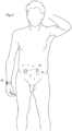
- the system can be arranged on a person's body such as illustrated in Fig. 3 .
- the capacitor plates 1, 3 can e.g. be arranged at the person's waist region.
- the internal capacitor plate 3 is seen to be surrounded by the electrical insulator 7, this for instance comprising two electrically insulated sheets between the electrically conducting plate is placed, the sheets being welded to each other at their margin region to provide a hermetic enclosure.
- the internal capacitor plate can be integrated with its driver circuits and power supply in one enclosure, the driver circuits connected to an implanted device 41 having its own power supply 43, e.g. an electrochemical cell.
- the driver circuits can be integrated with control circuits provided for the implanted device and then the power supply 43 also supplies power to the driver circuits.
- the external capacitor plate 1 and its driver circuits 9 and power supply 13 can be integrated in a wristwatch 45.
- the internal capacitor plate 3, not seen in Fig. 3 for this case, may be located directly under the person's skin region.
- the driver circuits 11, the power supply 15 and the internal capacitor plate 3 are seen to be separate units, only connected by electrical cables. They can also be integrated as one single unit, placed at the sides of each other inside a common enclosure or housing 47, see Fig. 4a , which can be made from an electrically insulating material, forming the necessary electrically insulation of the capacitor plate.
- the communication channel or path having a capacitive coupling as described above should have a constant impedance which is as small as possible in order to ensure that the communication signals are appropriately transferred.
- the capacitance of the capacitor used having one capacitor plate implanted in a patient's body is not constant due to the facts that the plates can move in relation to each other and that body functions in the tissues located between the capacitor plates can change.
- the frequency used for the communication is substantially constant if e.g. a carrier signal which is modulated is used or pulses of a definite frequency is used. Also, the frequency has to be as large as possible to make the impedance small.
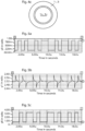
- the capacitor plates 1, 3 can be divided to each include a first plate and a second plate, see Fig. 4b .
- the two plates on the sending side can be then provided with signals which are the inverse of each other.
- the first plate can be provided with the direct signal and be denoted 3+ and the second plate can be provided with the inverted signal and then be denoted 3-.
- the inversion of signals can be easily achieved by arranging an inverter circuit such as that indicated at 50.
- an inverter circuit such as that indicated at 50.
- the external capacitor plate 1 must be configured in a similar and corresponding way, having one portion, not shown, for the direct signal and one portion, not shown, for the inverted signal.
- the dual capacitor plates used in this case can for ease of positioning be configured as concentric circular fields as seen Fig. 4c , at least one of which is annular.
- One capacitor portion 1+, 3+ can e.g. be a central circular field that is surrounded by an annular circular field 1-, 3-.
- the signals used in the communication between the external and internal devices can e.g. be electric pulses, e.g. substantially rectangular pulses.
- a suitable coding of the information could be used.
- Manchester coding can be used.
- Manchester encoding is a special case of binary phase shift keying where each bit of data is signified by at least one transition.
- the encoding is therefore self-clocking which makes accurate synchronization of the data stream possible.
- a "1" can be represented by a transition from a high to a low level and a "0" can be represented by a transition from a low to a high electrical level.
- In the electrical signal there are also transitions between the two levels that do not represent any information but are necessary in order that the transitions representing information can be arranged in the electrical, such extra transitions thus inserted when sending two equal consecutive bits of information.
- the digital information to be communicated can be represented as transitions of a signal, such as transitions between states or levels of a signal, these states or levels being for example different frequencies, different voltage levels or different levels of the amplitude of a carrier wave.
- transitions of a signal such as transitions between states or levels of a signal, these states or levels being for example different frequencies, different voltage levels or different levels of the amplitude of a carrier wave.
- binary information only two states or levels are required.
- a "0" is represented by a transition of a first kind such as from a first state to a second state
- a "1" is represented by a transition of a second, different kind such as from a second state to a first state.
- there are always consecutive sequences of the same symbol such as of "0:s" and "1:s”.
- the first symbol in such a sequence is then represented by the respective transition but for the following symbols in the sequence this transition can obviously not be used. Thus, in one case, for the following symbols no transition at all is used. Since the transitions are sent in a fixed rate, these following symbols can still be decoded. Thus, such a method requires that in receiving and decoding the signal, a clock signal for the times when the transitions are supposed to occur, such as for the start times of the transitions, is available.
- a clock signal can be obtained in the receiving side by sending, from the transmitting side, initially or at suitably repeated times, a sequence of transitions in the fixed rate, such a sequence then represented e.g. by the symbol sequence "10101010".
- Each of the symbols or bits of the communicated information can thus be generally represented as a variation of the derivative of a signal, the derivative taken in regard of time. Such a variation can then be e.g. positive pulse or a negative pulse.
- Fig. 6 is a circuit diagram of driver circuits 9, 11 comprising a transceiver that can be used in this case.
- the transmitted signal is picked up by the capacitor plate 1, 3.
- the DC level of the signal is by the resistor R22 pulled to 2.5V which is equal to VCC/2.
- the received signal is provided to a preamplifier stage 51 including an amplifier U9 before it is passed to filter stages.
- the amplifier has a high input impedance and a low bias current.
- the signal is then provided to a highpass filter stage 53 that is configured as a second order active high pass filter including an amplifier U10 as its active element. This filter stage removes low frequency interfering signals and noise.
- the signal is passed to a lowpass filter stage 55 being a passive filter of RC-type, comprising a resistor R41 and a capacitor C8 to remove high frequency noise.
- the signal is then provided to a signal detector stage that here is designed as a comparator 57 stage having hysteresis.
- the received and filtered signal is fed to the inverting input of a comparator U7.
- the same signal is also first even more low pass filtered in a passive RC-filter including R41 and C14 and then fed to the non-inverting input of the comparator via a resistor R6.
- the resistor R6 and the feedback resistor R12 form the hysteresis feedback.
- the comparator U7 has hysteresis in order to output a square wave in Manchester code even if the signal drops down below the DC level.
- An example of a received and filter signal can be seen in Fig. 5b and the output from the comparator U7 in Fig. 5c .
- the microcontroller U19 is used to decode the received Manchester stream into useful data. This is achieved by measuring the time between rising and falling edges.
- the microcontroller receives a preamble consisting of the repeated pattern "10101010". Since the only transitions that occur in that pattern are the bit transitions the preamble can be used to synchronize the data, i.e. to form a clock signal.
- the microcontroller can begin to translate the Manchester stream into useful data.
- amplitude modulation For instance, a carrier frequency can be on/off-modulated to output bursts of the electrical signal.
- the transmission stage 21 has a signal generator U22, that can be enabled by a signal "OSC_POW” from the microcontroller U19 in the microcontroller stage, the signal opening a transistor U4.
- the signal generator U22 outputs a oscillatory signal having a frequency of about 1.4 MHz that is set by the resistors R30 and R54.
- the output from the signal generator U22 is fed to the gate of another transistor U3.
- Another signal "OSC_EN" from the microcontroller is used to modulate the amplitude of the signal by being provided the gate of a transistor U2.
- the transistor U2 and resistor R43 are provided to make it possible to transmit a voltage higher than 5V.
- the transmitted signal is picked up by the capacitor plate connected to J4.
- the DC level of the received signal is by the resistor 22 pulled to 2.5V which is equal to VCC/2.
- the received is provided to a preamplifier stage 61 including an amplifier U9 having a high input impedance and a low bias current.
- the amplified signal is passed to a bandpass filter 63.
- the bandpass filter is a second order active band pass filter including an amplifier U10 as its active element.
- the filtered signal is provided to a variable gain amplifier 65 including a non-inverting amplifier U13.
- a resistor connects the inverting input of the non-inverting amplifier to a reference voltage that can be chosen by setting an analog switch U17.
- the gain of the variable gain amplifier 65 can therefore be set by the microcontroller 27 by control signals "VGA1-4".
- the signal is half-wave rectified in a rectifier stage 67 including an the amplifier U18 having two diodes D14 connected in its feedback loop.
- the rectified signal is by a passive low pass RC-filter 69 including a resistor R50 and a capacitor C28 to output a rectangular wave.
- the rectangular wave is high when the amplitude of the received signal is high or on and it is low when the amplitude is off or zero.
- the wanted signal is detected in a signal detector or comparator stage 35 by being provided to the non-inverting input of a comparator U21.
- the signal is also simultaneously low pass filtered by the RC-filter arranged by the resistor R52 and the capacitor C40 to provide an averaged signal to the inverting input.
- the signal "DATA" output from the comparator U21 is fed to the microcontroller 27 to decode the received data.
- the transmitted signal is balanced in the meaning that it is on and off for the same amount of time.
- the data can for that reason, also in this case, be encoded using Manchester code as described above.
- FSK frequency shift keying
- a received frequency is transformed into a '0' or '1'.
- PLL phase locked loop
- DPLL digital phase locked loop
- Such a digital demodulating circuit comprises a pfd or phase detector, a loop filter, a VCO counter and a decider.
- the phase detector looks on the incoming signal and compares it to the generated signal in the VCO counter. If any of the signals goes high before the other, this information is sent to the loop filter.
- the loop filter gets the information about which signal goes high first and translates this to a control signal for the VCO counter. This signal is the preset for the counter inside VCO counter.
- the VCO counter is a counter that always counts down and has a load and preset inputs. These inputs are controlled by the loop filter.
- the decider is a unit or circuit which creates the data signal. This is done by looking at the preset signals and, depending on the value, choosing between a '0' and a '1'.
Landscapes
- Health & Medical Sciences (AREA)
- Life Sciences & Earth Sciences (AREA)
- Engineering & Computer Science (AREA)
- Animal Behavior & Ethology (AREA)
- Veterinary Medicine (AREA)
- Public Health (AREA)
- Biomedical Technology (AREA)
- General Health & Medical Sciences (AREA)
- Physics & Mathematics (AREA)
- Pathology (AREA)
- Molecular Biology (AREA)
- Surgery (AREA)
- Medical Informatics (AREA)
- Heart & Thoracic Surgery (AREA)
- Biophysics (AREA)
- Radiology & Medical Imaging (AREA)
- Nuclear Medicine, Radiotherapy & Molecular Imaging (AREA)
- Computer Networks & Wireless Communication (AREA)
- Acoustics & Sound (AREA)
- Computational Linguistics (AREA)
- Audiology, Speech & Language Pathology (AREA)
- Human Computer Interaction (AREA)
- Multimedia (AREA)
- Signal Processing (AREA)
- Artificial Intelligence (AREA)
- Near-Field Transmission Systems (AREA)
Applications Claiming Priority (6)
| Application Number | Priority Date | Filing Date | Title |
|---|---|---|---|
| SE0802163 | 2008-10-10 | ||
| US22782209P | 2009-07-23 | 2009-07-23 | |
| EP09819520.9A EP2346570B1 (de) | 2008-10-10 | 2009-10-12 | System zur übertragung von informationen zwischen einem implantat und einer externen vorrichtung |
| EP21169101.9A EP3888740B1 (de) | 2008-10-10 | 2009-10-12 | System zur informationsübertragung |
| EP16193176.1A EP3228355B1 (de) | 2008-10-10 | 2009-10-12 | Kapazitives energierückkopplungsdatensystem |
| PCT/SE2009/051159 WO2010042066A1 (en) | 2008-10-10 | 2009-10-12 | System for transferring information between an implant and an external device |
Related Parent Applications (3)
| Application Number | Title | Priority Date | Filing Date |
|---|---|---|---|
| EP21169101.9A Division EP3888740B1 (de) | 2008-10-10 | 2009-10-12 | System zur informationsübertragung |
| EP16193176.1A Division EP3228355B1 (de) | 2008-10-10 | 2009-10-12 | Kapazitives energierückkopplungsdatensystem |
| EP09819520.9A Division EP2346570B1 (de) | 2008-10-10 | 2009-10-12 | System zur übertragung von informationen zwischen einem implantat und einer externen vorrichtung |
Publications (2)
| Publication Number | Publication Date |
|---|---|
| EP4389194A2 true EP4389194A2 (de) | 2024-06-26 |
| EP4389194A3 EP4389194A3 (de) | 2024-09-04 |
Family
ID=42100832
Family Applications (4)
| Application Number | Title | Priority Date | Filing Date |
|---|---|---|---|
| EP24156772.6A Withdrawn EP4389194A3 (de) | 2008-10-10 | 2009-10-12 | System zur informationsübertragung |
| EP16193176.1A Active EP3228355B1 (de) | 2008-10-10 | 2009-10-12 | Kapazitives energierückkopplungsdatensystem |
| EP09819520.9A Active EP2346570B1 (de) | 2008-10-10 | 2009-10-12 | System zur übertragung von informationen zwischen einem implantat und einer externen vorrichtung |
| EP21169101.9A Active EP3888740B1 (de) | 2008-10-10 | 2009-10-12 | System zur informationsübertragung |
Family Applications After (3)
| Application Number | Title | Priority Date | Filing Date |
|---|---|---|---|
| EP16193176.1A Active EP3228355B1 (de) | 2008-10-10 | 2009-10-12 | Kapazitives energierückkopplungsdatensystem |
| EP09819520.9A Active EP2346570B1 (de) | 2008-10-10 | 2009-10-12 | System zur übertragung von informationen zwischen einem implantat und einer externen vorrichtung |
| EP21169101.9A Active EP3888740B1 (de) | 2008-10-10 | 2009-10-12 | System zur informationsübertragung |
Country Status (4)
| Country | Link |
|---|---|
| US (2) | US20110201276A1 (de) |
| EP (4) | EP4389194A3 (de) |
| ES (1) | ES2974072T3 (de) |
| WO (1) | WO2010042066A1 (de) |
Families Citing this family (10)
| Publication number | Priority date | Publication date | Assignee | Title |
|---|---|---|---|---|
| MX2010004087A (es) * | 2007-10-16 | 2010-08-11 | Milux Holding Sa | Metodo y aparato para suministrar energia a un dispositivo medico. |
| CA2776502A1 (en) * | 2008-10-10 | 2010-04-15 | Peter Forsell | Charger for implant |
| EP2568615A4 (de) * | 2010-05-07 | 2015-04-08 | Samsung Electronics Co Ltd | Vorrichtung zum empfang eines analogen basisband-signals |
| EP2433675B1 (de) * | 2010-09-24 | 2013-01-09 | Sorin CRM SAS | Aktive implantierbare medizinische Vorrichtung, die drahtlose Kommunikationsmittel umfasst, die über elektrische Impulse kommunizieren, die von den interstitiellen Geweben des Körpers weitergeleitet werden |
| EP2441491B1 (de) | 2010-10-18 | 2013-01-09 | Sorin CRM SAS | Autonomes aktives medizinisches Implantat mit einem Aufwachstromkreis zur Stromzuführung beim Empfang von Impulsen, die vom interstitiellen Gewebe des Körpers übertragen werden |
| US9166562B2 (en) | 2013-02-25 | 2015-10-20 | Qualcomm Incorporated | Impedance transformation network for improved driver circuit performance |
| US10381874B2 (en) * | 2011-03-25 | 2019-08-13 | Qualcomm Incorporated | Filter for improved driver circuit efficiency and method of operation |
| WO2013112080A1 (en) * | 2012-01-23 | 2013-08-01 | Telefonaktiebolaget L M Ericsson (Publ) | Handling of signals transmitted through a human body |
| KR102418955B1 (ko) * | 2016-01-19 | 2022-07-11 | 한국전자통신연구원 | 채널 적응형 인체 통신 시스템 |
| EP4204997B1 (de) * | 2020-08-31 | 2025-11-19 | Implantica Patent Ltd | Verfahren und vorrichtungen zur sicheren kommunikation mit und zum betrieb eines implantats |
Family Cites Families (25)
| Publication number | Priority date | Publication date | Assignee | Title |
|---|---|---|---|---|
| US4987897A (en) * | 1989-09-18 | 1991-01-29 | Medtronic, Inc. | Body bus medical device communication system |
| US5702431A (en) * | 1995-06-07 | 1997-12-30 | Sulzer Intermedics Inc. | Enhanced transcutaneous recharging system for battery powered implantable medical device |
| CN1227843C (zh) * | 1997-05-02 | 2005-11-16 | 精工爱普生株式会社 | 生物体用偏光通信系统 |
| US6562001B2 (en) * | 2000-01-21 | 2003-05-13 | Medtronic Minimed, Inc. | Microprocessor controlled ambulatory medical apparatus with hand held communication device |
| SE0000372D0 (sv) * | 2000-02-07 | 2000-02-07 | Pacesetter Ab | Medical system |
| US7221981B2 (en) * | 2002-03-28 | 2007-05-22 | Northstar Neuroscience, Inc. | Electrode geometries for efficient neural stimulation |
| US6772011B2 (en) * | 2002-08-20 | 2004-08-03 | Thoratec Corporation | Transmission of information from an implanted medical device |
| US7559926B1 (en) * | 2003-01-13 | 2009-07-14 | Advanced Neuromodulation Systems, Inc. | Actuation system and method for an implantable infusion pump |
| US8155586B2 (en) * | 2003-01-25 | 2012-04-10 | Korea Institute Of Science And Technology | Method and system for data communication using a body |
| US7623827B2 (en) * | 2003-10-20 | 2009-11-24 | Cochlear Limited | Voltage overshoot protection |
| US7406105B2 (en) * | 2004-03-03 | 2008-07-29 | Alfred E. Mann Foundation For Scientific Research | System and method for sharing a common communication channel between multiple systems of implantable medical devices |
| US20050288739A1 (en) * | 2004-06-24 | 2005-12-29 | Ethicon, Inc. | Medical implant having closed loop transcutaneous energy transfer (TET) power transfer regulation circuitry |
| WO2006045148A2 (en) * | 2004-10-28 | 2006-05-04 | Cochlear Limited | Transcutaneous capacitive data link |
| EP1729489A1 (de) * | 2005-05-31 | 2006-12-06 | Infineon Technologies AG | Methode zur Messung einer kapazitiven Eigenschaft einer Kommunikationsleitung und entsprechende Vorrichtung |
| WO2007028035A2 (en) * | 2005-09-01 | 2007-03-08 | Proteus Biomedical, Inc. | Implantable zero-wire communications system |
| US7720547B2 (en) * | 2006-01-04 | 2010-05-18 | Kenergy, Inc. | Extracorporeal power supply with a wireless feedback system for an implanted medical device |
| JP4934325B2 (ja) * | 2006-02-17 | 2012-05-16 | 株式会社フジクラ | プリント配線板の接続構造及びプリント配線板の接続方法 |
| AT503122B1 (de) * | 2006-07-25 | 2007-08-15 | Evva Werke | Vorrichtung zur zutrittskontrolle sowie schreib-/leseeinrichtung |
| US7602142B2 (en) * | 2007-04-02 | 2009-10-13 | Visteon Global Technologies, Inc. | System for inductive power transfer |
| EP2183020B1 (de) * | 2007-08-10 | 2016-09-28 | Med-El Elektromedizinische Geräte GmbH | Pulsbreitenandaption für induktive verbindungen |
| MX2010004087A (es) * | 2007-10-16 | 2010-08-11 | Milux Holding Sa | Metodo y aparato para suministrar energia a un dispositivo medico. |
| EP2227914A1 (de) * | 2007-10-30 | 2010-09-15 | 3Win N.V. | Am körper getragenes drahtloses wandlermodul |
| US8081925B2 (en) * | 2008-05-08 | 2011-12-20 | Boston Scientific Neuromodulation Corporation | Transceiver for an implantable medical device having switchable series-to-parallel tank circuit |
| US9659423B2 (en) * | 2008-12-15 | 2017-05-23 | Proteus Digital Health, Inc. | Personal authentication apparatus system and method |
| JP2014514032A (ja) * | 2011-03-11 | 2014-06-19 | プロテウス デジタル ヘルス, インコーポレイテッド | 様々な物理的構成を備えた着用式個人身体関連装置 |
-
2009
- 2009-10-12 US US13/123,252 patent/US20110201276A1/en not_active Abandoned
- 2009-10-12 EP EP24156772.6A patent/EP4389194A3/de not_active Withdrawn
- 2009-10-12 EP EP16193176.1A patent/EP3228355B1/de active Active
- 2009-10-12 EP EP09819520.9A patent/EP2346570B1/de active Active
- 2009-10-12 ES ES21169101T patent/ES2974072T3/es active Active
- 2009-10-12 EP EP21169101.9A patent/EP3888740B1/de active Active
- 2009-10-12 WO PCT/SE2009/051159 patent/WO2010042066A1/en not_active Ceased
-
2024
- 2024-10-03 US US18/905,159 patent/US20250082223A1/en active Pending
Also Published As
| Publication number | Publication date |
|---|---|
| US20110201276A1 (en) | 2011-08-18 |
| EP2346570B1 (de) | 2016-10-12 |
| EP3228355B1 (de) | 2021-04-21 |
| EP3888740A1 (de) | 2021-10-06 |
| EP4389194A3 (de) | 2024-09-04 |
| EP3888740B1 (de) | 2024-02-21 |
| EP2346570A1 (de) | 2011-07-27 |
| US20250082223A1 (en) | 2025-03-13 |
| WO2010042066A1 (en) | 2010-04-15 |
| EP3888740C0 (de) | 2024-02-21 |
| ES2974072T3 (es) | 2024-06-25 |
| EP3228355A1 (de) | 2017-10-11 |
| EP2346570A4 (de) | 2012-11-28 |
Similar Documents
| Publication | Publication Date | Title |
|---|---|---|
| US20250082223A1 (en) | System for transferring information | |
| US8825173B2 (en) | Method and apparatus for supplying energy to a medical device | |
| US20250152036A1 (en) | Voice control system for an implant | |
| EP2764889B1 (de) | Implantierbare medizinische Vorrichtung, medizinisches System und Verfahren zur Datenkommunikation | |
| US4681111A (en) | Analog and digital telemetry system for an implantable device | |
| US9375581B2 (en) | Implantable stimulation device, stimulation system and method for data communication | |
| US6889086B2 (en) | Passive telemetry system for implantable medical device | |
| US12251209B2 (en) | Voice control system for an implant | |
| Khanna | Wireless communications and powering of implants | |
| ES2879922T3 (es) | Sistema de datos de acoplamiento capacitivo con retroalimentación de energía |
Legal Events
| Date | Code | Title | Description |
|---|---|---|---|
| PUAI | Public reference made under article 153(3) epc to a published international application that has entered the european phase |
Free format text: ORIGINAL CODE: 0009012 |
|
| STAA | Information on the status of an ep patent application or granted ep patent |
Free format text: STATUS: THE APPLICATION HAS BEEN PUBLISHED |
|
| AC | Divisional application: reference to earlier application |
Ref document number: 2346570 Country of ref document: EP Kind code of ref document: P Ref document number: 3228355 Country of ref document: EP Kind code of ref document: P Ref document number: 3888740 Country of ref document: EP Kind code of ref document: P |
|
| AK | Designated contracting states |
Kind code of ref document: A2 Designated state(s): AT BE BG CH CY CZ DE DK EE ES FI FR GB GR HR HU IE IS IT LI LT LU LV MC MK MT NL NO PL PT RO SE SI SK SM TR |
|
| REG | Reference to a national code |
Ref country code: DE Ref legal event code: R079 Free format text: PREVIOUS MAIN CLASS: A61N0001050000 Ipc: A61N0001378000 |
|
| PUAL | Search report despatched |
Free format text: ORIGINAL CODE: 0009013 |
|
| AK | Designated contracting states |
Kind code of ref document: A3 Designated state(s): AT BE BG CH CY CZ DE DK EE ES FI FR GB GR HR HU IE IS IT LI LT LU LV MC MK MT NL NO PL PT RO SE SI SK SM TR |
|
| RIC1 | Information provided on ipc code assigned before grant |
Ipc: A61N 1/05 20060101ALI20240726BHEP Ipc: A61F 2/02 20060101ALI20240726BHEP Ipc: A61N 1/378 20060101AFI20240726BHEP |
|
| STAA | Information on the status of an ep patent application or granted ep patent |
Free format text: STATUS: THE APPLICATION IS DEEMED TO BE WITHDRAWN |
|
| 18D | Application deemed to be withdrawn |
Effective date: 20250305 |