EP4389372A1 - Découpeuse pour des aliments de forme longue - Google Patents
Découpeuse pour des aliments de forme longue Download PDFInfo
- Publication number
- EP4389372A1 EP4389372A1 EP23217992.9A EP23217992A EP4389372A1 EP 4389372 A1 EP4389372 A1 EP 4389372A1 EP 23217992 A EP23217992 A EP 23217992A EP 4389372 A1 EP4389372 A1 EP 4389372A1
- Authority
- EP
- European Patent Office
- Prior art keywords
- shaft
- cutting machine
- area
- region
- machine according
- Prior art date
- Legal status (The legal status is an assumption and is not a legal conclusion. Google has not performed a legal analysis and makes no representation as to the accuracy of the status listed.)
- Pending
Links
- 235000013305 food Nutrition 0.000 title claims description 29
- 238000005520 cutting process Methods 0.000 claims abstract description 75
- 238000003780 insertion Methods 0.000 claims description 7
- 230000037431 insertion Effects 0.000 claims description 7
- 238000005192 partition Methods 0.000 claims description 6
- 238000004140 cleaning Methods 0.000 description 5
- 238000012423 maintenance Methods 0.000 description 5
- 235000008429 bread Nutrition 0.000 description 2
- 230000006378 damage Effects 0.000 description 2
- 208000027418 Wounds and injury Diseases 0.000 description 1
- 235000013351 cheese Nutrition 0.000 description 1
- 210000000078 claw Anatomy 0.000 description 1
- 238000011109 contamination Methods 0.000 description 1
- 238000013461 design Methods 0.000 description 1
- 238000011161 development Methods 0.000 description 1
- 230000018109 developmental process Effects 0.000 description 1
- 208000014674 injury Diseases 0.000 description 1
- 239000000314 lubricant Substances 0.000 description 1
Images



Classifications
-
- B—PERFORMING OPERATIONS; TRANSPORTING
- B26—HAND CUTTING TOOLS; CUTTING; SEVERING
- B26D—CUTTING; DETAILS COMMON TO MACHINES FOR PERFORATING, PUNCHING, CUTTING-OUT, STAMPING-OUT OR SEVERING
- B26D7/00—Details of apparatus for cutting, cutting-out, stamping-out, punching, perforating, or severing by means other than cutting
- B26D7/06—Arrangements for feeding or delivering work of other than sheet, web, or filamentary form
- B26D7/0641—Arrangements for feeding or delivering work of other than sheet, web, or filamentary form using chutes, hoppers, magazines
-
- B—PERFORMING OPERATIONS; TRANSPORTING
- B26—HAND CUTTING TOOLS; CUTTING; SEVERING
- B26D—CUTTING; DETAILS COMMON TO MACHINES FOR PERFORATING, PUNCHING, CUTTING-OUT, STAMPING-OUT OR SEVERING
- B26D1/00—Cutting through work characterised by the nature or movement of the cutting member or particular materials not otherwise provided for; Apparatus or machines therefor; Cutting members therefor
- B26D1/01—Cutting through work characterised by the nature or movement of the cutting member or particular materials not otherwise provided for; Apparatus or machines therefor; Cutting members therefor involving a cutting member which does not travel with the work
- B26D1/12—Cutting through work characterised by the nature or movement of the cutting member or particular materials not otherwise provided for; Apparatus or machines therefor; Cutting members therefor involving a cutting member which does not travel with the work having a cutting member moving about an axis
- B26D1/14—Cutting through work characterised by the nature or movement of the cutting member or particular materials not otherwise provided for; Apparatus or machines therefor; Cutting members therefor involving a cutting member which does not travel with the work having a cutting member moving about an axis with a circular cutting member, e.g. disc cutter
- B26D1/157—Cutting through work characterised by the nature or movement of the cutting member or particular materials not otherwise provided for; Apparatus or machines therefor; Cutting members therefor involving a cutting member which does not travel with the work having a cutting member moving about an axis with a circular cutting member, e.g. disc cutter rotating about a movable axis
- B26D1/16—Cutting through work characterised by the nature or movement of the cutting member or particular materials not otherwise provided for; Apparatus or machines therefor; Cutting members therefor involving a cutting member which does not travel with the work having a cutting member moving about an axis with a circular cutting member, e.g. disc cutter rotating about a movable axis mounted on a movable arm or the like
-
- B—PERFORMING OPERATIONS; TRANSPORTING
- B26—HAND CUTTING TOOLS; CUTTING; SEVERING
- B26D—CUTTING; DETAILS COMMON TO MACHINES FOR PERFORATING, PUNCHING, CUTTING-OUT, STAMPING-OUT OR SEVERING
- B26D7/00—Details of apparatus for cutting, cutting-out, stamping-out, punching, perforating, or severing by means other than cutting
-
- B—PERFORMING OPERATIONS; TRANSPORTING
- B26—HAND CUTTING TOOLS; CUTTING; SEVERING
- B26D—CUTTING; DETAILS COMMON TO MACHINES FOR PERFORATING, PUNCHING, CUTTING-OUT, STAMPING-OUT OR SEVERING
- B26D7/00—Details of apparatus for cutting, cutting-out, stamping-out, punching, perforating, or severing by means other than cutting
- B26D7/06—Arrangements for feeding or delivering work of other than sheet, web, or filamentary form
- B26D7/0683—Arrangements for feeding or delivering work of other than sheet, web, or filamentary form specially adapted for elongated articles
-
- B—PERFORMING OPERATIONS; TRANSPORTING
- B26—HAND CUTTING TOOLS; CUTTING; SEVERING
- B26D—CUTTING; DETAILS COMMON TO MACHINES FOR PERFORATING, PUNCHING, CUTTING-OUT, STAMPING-OUT OR SEVERING
- B26D2210/00—Machines or methods used for cutting special materials
- B26D2210/02—Machines or methods used for cutting special materials for cutting food products, e.g. food slicers
-
- B—PERFORMING OPERATIONS; TRANSPORTING
- B26—HAND CUTTING TOOLS; CUTTING; SEVERING
- B26D—CUTTING; DETAILS COMMON TO MACHINES FOR PERFORATING, PUNCHING, CUTTING-OUT, STAMPING-OUT OR SEVERING
- B26D2210/00—Machines or methods used for cutting special materials
- B26D2210/02—Machines or methods used for cutting special materials for cutting food products, e.g. food slicers
- B26D2210/06—Machines or methods used for cutting special materials for cutting food products, e.g. food slicers for bread, e.g. bread slicing machines for use in a retail store
Definitions
- the invention relates to a cutting machine with which bread, cheese and similar string-shaped foods can be cut into slices of any thickness.
- the cutting machine according to the invention can in particular be a circular knife machine.
- Circular knife machines for cutting a food strand into slices are generally known. Such cutting machines have a circular cutting blade that can rotate around its central axis and can also be swiveled around in a circular path. During this swiveling movement, it is guided through the strand-shaped food to be cut into slices. The strand-shaped food is fed to the cutting blade in a channel-like shaft and cut into slices. The cut slices are stored upright on a storage area arranged downstream of the cutting blade in the feed direction. In the area of this storage area for the cut slice package, a slice support is usually arranged to prevent the cut slices from falling over.
- the motor drive for the cutting blade is located underneath the shaft floor in this type of cutting machine.
- the drive shaft for driving the eccentric arm of the cutting blade is also located underneath the shaft floor. The cutting blade is thus guided upwards through the slot from below, so that a fairly large portion of the cutting blade is guided through the slot. This means that the slot has to be relatively wide.
- the motor drive is located above the shaft area.
- the cutting blade is therefore guided from above through the food to be cut.
- the cutting blade only needs to be immersed in the slot to a small extent. This means that the slot can be made much narrower.
- a partition wall In order to operate the cutting blade safely, a partition wall must be inserted between the shaft and the motor drive, which runs the entire length of the shaft. There is a wide slot in this partition wall through which the cutting blade is guided downwards and forwards into the shaft area.
- the invention is based on the object of specifying an improved cutting machine in which the slot in the shaft can be made as narrow as possible.
- the cutting machine for strand-shaped foodstuffs has a cutting blade for the strand-shaped foodstuff and a shaft for receiving the strand-shaped foodstuff.
- the shaft has a first and a second shaft area, which are at least partially separated from one another by a slot.
- the cutting blade can be inserted into this slot.
- the drive shaft for driving the eccentric arm of the cutting blade is arranged above the shaft.
- an intermediate wall is arranged behind the shaft, which runs parallel to the longitudinal direction of the shaft. This intermediate wall is only present in the area of the first shaft area or only in the area of the second shaft area.
- the cutting blade is positioned next to the intermediate wall.
- the partition wall can protect the components behind the shaft, such as motor drives or control elements, from damage or deliberate manipulation.
- the cutting blade can be arranged above the shaft so that the slot between the two shaft areas can be made narrow.
- no slot for the cutting blade needs to be provided in the partition wall, as the partition wall ends in the area of the slot in the shaft.
- the design of the chamber means that the critical components can be even better protected from contamination by the food being cut. This means that crumbs of food adhering to the cutting blade can no longer get into the chamber area. At the same time, the cutting blade does not come into contact with the lubricants that may be necessary in the area of the motor drive. This means that hygienic conditions can be further improved.
- the eccentric arm is located outside the chamber and is arranged parallel to the side wall.
- the cutting blade is rotatably mounted on this eccentric arm.
- the chamber can preferably be arranged in the area of the first shaft area. In this way, the cutting blade can be arranged with its flat cutting surface as close as possible to the side wall, while the angled surface of the cutting blade points away from the side wall.
- the motor drive for the drive shaft can be arranged anywhere within the cutting machine.
- the motor drive can therefore be arranged wherever it is practical in terms of space.
- the motor drive can preferably be arranged behind the shaft.
- the chamber can be covered by a lid.
- the chamber and thus possibly also the motor drive can be protected and closed from the top.
- the motor drive can still be easily accessible, for example to carry out maintenance or repair work.
- the lid can be removable for this purpose.
- the lid can only be present in the area of the chamber.
- the lid can also be designed to cover the entire width of the machine.
- a housing flap can be provided above the chamber.
- the housing flap can in particular be mounted so that it can pivot about a rotation axis in order to be able to open the housing flap easily. If the cover above the chamber runs across the entire width of the machine, a housing flap may also be dispensed with.
- the shaft of the cutting machine can have an insertion area for the strand-shaped food and a removal area for the cut strand-shaped food. Parts of the shaft area of the removal area can be pivoted about a rotation axis parallel to the feed direction.
- the entire shaft area of the removal area can also be designed to be pivotable. Alternatively or additionally, at least parts of the shaft area of the removal area can be designed to be removable. The entire shaft area of the removal area can also be removable.
- the removal area for the sliced food strand can correspond to the insertion area for the food strand.
- the sliced package can be removed from the same place on the cutting machine where the food to be sliced was inserted.
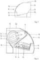
- the cutting machine 10 is designed as a circular knife machine with a circular knife 12.
- the circular knife 12 is coupled in the usual way via a drive shaft 14 to a motor drive 16, which ensures the rotation of the circular knife 12 and its movement through the food to be cut.
- the food to be cut is bread.
- the housing 20 of the cutting machine 10 can be closed with a housing flap 22.
- the housing flap 22 extends over the entire housing 20 of the cutting machine 10 and is only opened for cleaning or maintenance work.
- the cutting machine 10 has a shaft 30, the longitudinal direction 32 of which corresponds to the feed direction of the inserted strand-shaped foodstuff.
- the shaft 30 is aligned approximately horizontally.
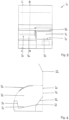
- the shaft 30 of the cutting machine 10 has a first, right shaft area 34 and a second, left shaft area 36, which are separated from each other by a slot 38.
- the circular blade 12 dips a little way into this slot 38 from above, so that the foodstuff present in the area of the slot 38 is cut at this point.
- a food slice is then created to the left of this slot 38. To the right of the slot 38, the food is still intact. Therefore, the insertion area for the food to be cut is in the area of the first, right-hand shaft area 34 and the removal area for the cut slice package is in the area of the second, left-hand shaft area 36.
- the insertion area and the removal area could also coincide. This can be the case in particular if the longitudinal direction 32 of the shaft 30 is approximately perpendicular to the longitudinal direction 24 of the cutting machine 10 is present. In this case, the longitudinal direction 32 of the shaft 30 would correspond to the transverse direction of the cutting machine 10.
- the two shaft areas 34, 36 of the cutting machine 10 are each approximately U-shaped.
- the first shaft area 34 has a shaft base 40, a rear wall 42 and a front wall 44.
- the front wall 44 is attached to the front 46 of the housing 20 of the cutting machine 10.
- the shaft base 40 is not aligned exactly horizontally; rather, the shaft base 40 is slightly inclined so that the shaft base 40 is slightly lower in the area of the front wall 44 than in the area of the rear wall 42.
- the food to be cut therefore rests with its base on the shaft base 40 and with its side on the front wall 44.
- the second shaft area 36 also has a shaft floor 50, a rear wall 52 and a front wall 54.
- the shaft floor 50 is slightly inclined so that the shaft floor 50 is slightly lower in the area of the front wall 54 than in the area of the rear wall 52.
- the disk package that is gradually formed thus rests with its bottom on the shaft floor 50 and with its side on the front wall 54.
- the food to be cut can be inserted by an operator - who can be a salesperson or an end customer - from the front 18 of the cutting machine 10.
- the flap 56 above the shaft 30 is first opened from the Fig.1 shown closed position. This makes the shaft 30 accessible so that the food to be cut can be placed on the shaft base 40 in the first shaft area 34 (insertion area).
- the cutting process can usually only be started when the flap 56 is closed. As long as the flap 56 is open, however, the circular blade 12 is blocked in order to prevent any risk of injury from the circular blade 12.
- the transport gripper 60 pushes it towards the slot 38.
- the transport gripper 60 has several claws 62 lying next to one another, which penetrate the end of the food to be cut from above during the cutting process.
- a slice support (not shown here) is arranged behind the slot 38.
- the slice support is pivotably mounted on an axis so that subsequent slices can move the slice support accordingly.
- a slice package gradually forms in the second shaft area 36 (removal area), which can be removed after the cutting process has ended.
- the flap 56 of the cutting machine 10 is opened again.
- the second shaft area 36 in the present example is designed to be pivotable about a rotation axis 68.
- the rotation axis 68 runs along the edge between the shaft base 50 and the rear wall 52.
- the rear wall 52 is designed to be stationary, while the shaft base 50 can be pivoted upwards together with the front wall 54.
- only the shaft base 50 can be designed to be pivotable.
- the rear wall 52 and the front wall 54 would be designed to be stationary, so that only the shaft base 50 can be pivoted upwards.
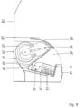
- a chamber 70 is formed diagonally above the first shaft area 34.
- the motor drive 16 for the circular blade 12 is positioned in this chamber 70.
- the chamber 70 is separated from the rest of the interior of the housing 20 of the cutting machine 10 by a side wall 72 and an intermediate wall 74.
- the side wall 72 runs parallel to the slot 38 between the two shaft areas 34, 36.
- the side wall 72 is arranged in the area of the slot 38 and runs in the area behind the first shaft area 34.
- the side wall 72 thus extends from the rear wall 42 of the shaft area 34 to the rear wall 76 of the housing 20 of the cutting machine.
- the intermediate wall 74 is formed diagonally and runs parallel to the longitudinal direction 32 of the shaft 30.
- the rear region of the intermediate wall 74 borders on the rear wall 42 of the first shaft region 34 and is arranged significantly lower than the front edge 78 of the intermediate wall 74.
- the front edge 78 of the intermediate wall 74 extends to just below the closed flap 22 of the cutting machine.
- the housing flap 22 there is a housing flap 22 above the chamber 70.
- the housing flap 22 closes the machine housing 20 from above so that it is not accessible.
- the housing flap 22 can be pivoted upwards about a pivot axis 26 in order to open the housing flap 22.
- this open state see Fig. 6 to 10 ) access to the machine housing 20 is possible. This may be necessary, for example, for maintenance purposes or for cleaning the cutting machine 10.
- the flap 56 can also be pivoted upwards about a pivot axis 58 for maintenance and/or cleaning purposes, as shown in Fig. 8 to 10 is shown.
- the chamber 70 is additionally covered by a cover 82.
- the cover 82 can be removed if necessary, in particular for maintenance and cleaning purposes.
- the cover 82 is only present in the area of the chamber 70.
- the cover 82 could also be present across the entire width of the machine.
- the housing flap 22 could also be dispensed with if necessary.
- the drive shaft 14 of the motor drive 16 extends through the side wall 72 of the chamber 70.
- An eccentric arm 80 is rotatably mounted on the drive shaft 14.
- the eccentric arm 80 runs parallel to the side wall 72.
- the circular blade 12 is rotatably mounted on the eccentric arm 80.
- To cut the food the eccentric arm 80 with the cutting blade 12 is first guided around the drive shaft 14 in an anti-clockwise direction from behind through the food to be cut.
- the circular blade 12 rotates so that a A food slice is created.
- the circular blade 12 only dips a little way into the slot 38.
- the slot 38 therefore only has to be very small so that the cut slices can be transported across the slot 38 without any problems.
- the motor drive can be positioned within the chamber 70. However, it would also be possible to provide the motor drive below the shaft 30, in particular below the shaft floors 40, 50. In addition, it would also be possible to provide the motor drive in the area behind the shaft 30. In this case, the motor drive could be positioned approximately at the same height as the shaft 30.
Landscapes
- Life Sciences & Earth Sciences (AREA)
- Forests & Forestry (AREA)
- Engineering & Computer Science (AREA)
- Mechanical Engineering (AREA)
- Food-Manufacturing Devices (AREA)
Applications Claiming Priority (1)
| Application Number | Priority Date | Filing Date | Title |
|---|---|---|---|
| DE102022134755.9A DE102022134755A1 (de) | 2022-12-23 | 2022-12-23 | Schneidmaschine für strangförmige Lebensmittel |
Publications (1)
| Publication Number | Publication Date |
|---|---|
| EP4389372A1 true EP4389372A1 (fr) | 2024-06-26 |
Family
ID=91270499
Family Applications (1)
| Application Number | Title | Priority Date | Filing Date |
|---|---|---|---|
| EP23217992.9A Pending EP4389372A1 (fr) | 2022-12-23 | 2023-12-19 | Découpeuse pour des aliments de forme longue |
Country Status (2)
| Country | Link |
|---|---|
| EP (1) | EP4389372A1 (fr) |
| DE (1) | DE102022134755A1 (fr) |
Citations (2)
| Publication number | Priority date | Publication date | Assignee | Title |
|---|---|---|---|---|
| DE102012007311A1 (de) | 2012-04-13 | 2013-10-17 | MW-Schickart Bäckereimaschinenbau GmbH & Co KG | Lebensmittel-Scheibenschneid- und Teilvorrichtung, insbesondere zum Schneiden oder Teilen von Brot |
| DE102014001511A1 (de) * | 2014-02-06 | 2015-08-06 | Rudi Siller | Schneidmaschine und Schneidverfahren für strangförmige Lebensmittel |
-
2022
- 2022-12-23 DE DE102022134755.9A patent/DE102022134755A1/de active Pending
-
2023
- 2023-12-19 EP EP23217992.9A patent/EP4389372A1/fr active Pending
Patent Citations (3)
| Publication number | Priority date | Publication date | Assignee | Title |
|---|---|---|---|---|
| DE102012007311A1 (de) | 2012-04-13 | 2013-10-17 | MW-Schickart Bäckereimaschinenbau GmbH & Co KG | Lebensmittel-Scheibenschneid- und Teilvorrichtung, insbesondere zum Schneiden oder Teilen von Brot |
| DE102012007311B4 (de) * | 2012-04-13 | 2021-06-24 | MW-Schickart Bäckereimaschinenbau GmbH & Co KG | Lebensmittel-Scheibenschneid- und Teilvorrichtung, insbesondere zum Schneiden oder Teilen von Brot |
| DE102014001511A1 (de) * | 2014-02-06 | 2015-08-06 | Rudi Siller | Schneidmaschine und Schneidverfahren für strangförmige Lebensmittel |
Also Published As
| Publication number | Publication date |
|---|---|
| DE102022134755A1 (de) | 2024-07-04 |
Similar Documents
| Publication | Publication Date | Title |
|---|---|---|
| EP3102376B1 (fr) | Méthode de découpe et machine de découpe d'aliments en forme de boudin | |
| EP2045053B1 (fr) | Machine de découpe à disques pour aliments en forme de tronçons | |
| EP2359992B2 (fr) | Machine de coupe d'un aliment en forme de tronçon | |
| EP3492398B1 (fr) | Machine d'emballage pourvue de couvercle de sécurité pliable | |
| DE19820004A1 (de) | Maschine zum Schneiden eines Gutsstrangs in Scheiben | |
| DE3113638A1 (de) | Schnitzelmaschine fuer lebensmittel | |
| DE102012007311B4 (de) | Lebensmittel-Scheibenschneid- und Teilvorrichtung, insbesondere zum Schneiden oder Teilen von Brot | |
| EP2635413B1 (fr) | Trancheuse à guidage de chariot extérieur et verrouillage de lame | |
| EP2322330A1 (fr) | Procédé et dispositif de coupe d'un tronçon de viande contenant des os en tranches | |
| DE102016010635B4 (de) | Schneidmaschine für strangförmige Lebensmittel | |
| DE102022134755A1 (de) | Schneidmaschine für strangförmige Lebensmittel | |
| DE102012100587A1 (de) | Schneidevorrichtung für Brot | |
| EP1938932A1 (fr) | Machine destinée à couper des produits alimentaires en forme de tronçon en rondelles, ainsi que procédé de coupe | |
| DE29713837U1 (de) | Knoblauchschneider | |
| EP2937191B1 (fr) | MACHINE DE DÉCOUPE DE PRODUITS ALIMENTAIRES DE FORME ALLONGéE | |
| DE102014011167B4 (de) | Schneidmaschine für strangförmige Lebensmittel | |
| EP4382268B1 (fr) | Machine de coupe pour produits alimentaires allongés | |
| EP3599067A1 (fr) | Machine de découpe pour produits alimentaires en forme de tige | |
| EP4538003A1 (fr) | Procédé et dispositif pour couper des produits alimentaires allongés | |
| DE102018003556A1 (de) | Schneidmaschine für strangförmige Lebensmittel | |
| EP1106312B1 (fr) | Machine de coupe pour produits alimentaires | |
| EP1136200B1 (fr) | Machine servant à couper des aliments en dés ou en bandes | |
| EP1147866A2 (fr) | Dispositif pour la coupe d'aliments | |
| DE29621949U1 (de) | Schneidemaschine für Lebensmittel | |
| DE102020007561A1 (de) | Schneidmaschine für strangförmige Lebensmittel |
Legal Events
| Date | Code | Title | Description |
|---|---|---|---|
| PUAI | Public reference made under article 153(3) epc to a published international application that has entered the european phase |
Free format text: ORIGINAL CODE: 0009012 |
|
| STAA | Information on the status of an ep patent application or granted ep patent |
Free format text: STATUS: THE APPLICATION HAS BEEN PUBLISHED |
|
| AK | Designated contracting states |
Kind code of ref document: A1 Designated state(s): AL AT BE BG CH CY CZ DE DK EE ES FI FR GB GR HR HU IE IS IT LI LT LU LV MC ME MK MT NL NO PL PT RO RS SE SI SK SM TR |
|
| STAA | Information on the status of an ep patent application or granted ep patent |
Free format text: STATUS: REQUEST FOR EXAMINATION WAS MADE |
|
| 17P | Request for examination filed |
Effective date: 20241104 |
|
| RBV | Designated contracting states (corrected) |
Designated state(s): AL AT BE BG CH CY CZ DE DK EE ES FI FR GB GR HR HU IE IS IT LI LT LU LV MC ME MK MT NL NO PL PT RO RS SE SI SK SM TR |