EP4389497A1 - Verwendung von vibrationsdaten und soh-rückkopplung zur steuerung der batteriepackvibration - Google Patents
Verwendung von vibrationsdaten und soh-rückkopplung zur steuerung der batteriepackvibration Download PDFInfo
- Publication number
- EP4389497A1 EP4389497A1 EP22214604.5A EP22214604A EP4389497A1 EP 4389497 A1 EP4389497 A1 EP 4389497A1 EP 22214604 A EP22214604 A EP 22214604A EP 4389497 A1 EP4389497 A1 EP 4389497A1
- Authority
- EP
- European Patent Office
- Prior art keywords
- vibration
- energy storage
- electrical energy
- storage system
- vehicle
- Prior art date
- Legal status (The legal status is an assumption and is not a legal conclusion. Google has not performed a legal analysis and makes no representation as to the accuracy of the status listed.)
- Pending
Links
- 238000004146 energy storage Methods 0.000 claims abstract description 106
- 238000000034 method Methods 0.000 claims abstract description 44
- 238000001228 spectrum Methods 0.000 claims abstract description 34
- 230000036541 health Effects 0.000 claims abstract description 32
- 238000012545 processing Methods 0.000 claims abstract description 12
- 230000007246 mechanism Effects 0.000 claims description 22
- 230000000694 effects Effects 0.000 claims description 10
- 230000001133 acceleration Effects 0.000 claims description 6
- 210000000352 storage cell Anatomy 0.000 claims description 6
- 238000004590 computer program Methods 0.000 claims description 5
- 230000032683 aging Effects 0.000 description 8
- 238000010586 diagram Methods 0.000 description 8
- 230000003044 adaptive effect Effects 0.000 description 6
- 238000001845 vibrational spectrum Methods 0.000 description 5
- 230000006870 function Effects 0.000 description 4
- 210000004027 cell Anatomy 0.000 description 3
- 230000002596 correlated effect Effects 0.000 description 3
- 238000013016 damping Methods 0.000 description 3
- 238000004458 analytical method Methods 0.000 description 2
- 238000010276 construction Methods 0.000 description 2
- 229910001416 lithium ion Inorganic materials 0.000 description 2
- 238000005259 measurement Methods 0.000 description 2
- 238000012986 modification Methods 0.000 description 2
- 230000004048 modification Effects 0.000 description 2
- 230000008569 process Effects 0.000 description 2
- 230000035882 stress Effects 0.000 description 2
- 230000005540 biological transmission Effects 0.000 description 1
- 238000009529 body temperature measurement Methods 0.000 description 1
- 238000004891 communication Methods 0.000 description 1
- 230000000875 corresponding effect Effects 0.000 description 1
- 230000000550 effect on aging Effects 0.000 description 1
- 238000005516 engineering process Methods 0.000 description 1
- 230000007613 environmental effect Effects 0.000 description 1
- 238000011156 evaluation Methods 0.000 description 1
- 230000006355 external stress Effects 0.000 description 1
- 238000001914 filtration Methods 0.000 description 1
- 239000004973 liquid crystal related substance Substances 0.000 description 1
- 238000004519 manufacturing process Methods 0.000 description 1
- 230000002093 peripheral effect Effects 0.000 description 1
- 230000009467 reduction Effects 0.000 description 1
- 230000035945 sensitivity Effects 0.000 description 1
- 238000010183 spectrum analysis Methods 0.000 description 1
- 238000012546 transfer Methods 0.000 description 1
Images



Classifications
-
- B—PERFORMING OPERATIONS; TRANSPORTING
- B60—VEHICLES IN GENERAL
- B60L—PROPULSION OF ELECTRICALLY-PROPELLED VEHICLES; SUPPLYING ELECTRIC POWER FOR AUXILIARY EQUIPMENT OF ELECTRICALLY-PROPELLED VEHICLES; ELECTRODYNAMIC BRAKE SYSTEMS FOR VEHICLES IN GENERAL; MAGNETIC SUSPENSION OR LEVITATION FOR VEHICLES; MONITORING OPERATING VARIABLES OF ELECTRICALLY-PROPELLED VEHICLES; ELECTRIC SAFETY DEVICES FOR ELECTRICALLY-PROPELLED VEHICLES
- B60L3/00—Electric devices on electrically-propelled vehicles for safety purposes; Monitoring operating variables, e.g. speed, deceleration or energy consumption
- B60L3/12—Recording operating variables ; Monitoring of operating variables
-
- B—PERFORMING OPERATIONS; TRANSPORTING
- B60—VEHICLES IN GENERAL
- B60L—PROPULSION OF ELECTRICALLY-PROPELLED VEHICLES; SUPPLYING ELECTRIC POWER FOR AUXILIARY EQUIPMENT OF ELECTRICALLY-PROPELLED VEHICLES; ELECTRODYNAMIC BRAKE SYSTEMS FOR VEHICLES IN GENERAL; MAGNETIC SUSPENSION OR LEVITATION FOR VEHICLES; MONITORING OPERATING VARIABLES OF ELECTRICALLY-PROPELLED VEHICLES; ELECTRIC SAFETY DEVICES FOR ELECTRICALLY-PROPELLED VEHICLES
- B60L58/00—Methods or circuit arrangements for monitoring or controlling batteries or fuel cells, specially adapted for electric vehicles
- B60L58/10—Methods or circuit arrangements for monitoring or controlling batteries or fuel cells, specially adapted for electric vehicles for monitoring or controlling batteries
- B60L58/16—Methods or circuit arrangements for monitoring or controlling batteries or fuel cells, specially adapted for electric vehicles for monitoring or controlling batteries responding to battery ageing, e.g. to the number of charging cycles or the state of health [SoH]
-
- B—PERFORMING OPERATIONS; TRANSPORTING
- B60—VEHICLES IN GENERAL
- B60L—PROPULSION OF ELECTRICALLY-PROPELLED VEHICLES; SUPPLYING ELECTRIC POWER FOR AUXILIARY EQUIPMENT OF ELECTRICALLY-PROPELLED VEHICLES; ELECTRODYNAMIC BRAKE SYSTEMS FOR VEHICLES IN GENERAL; MAGNETIC SUSPENSION OR LEVITATION FOR VEHICLES; MONITORING OPERATING VARIABLES OF ELECTRICALLY-PROPELLED VEHICLES; ELECTRIC SAFETY DEVICES FOR ELECTRICALLY-PROPELLED VEHICLES
- B60L15/00—Methods, circuits, or devices for controlling the traction-motor speed of electrically-propelled vehicles
- B60L15/20—Methods, circuits, or devices for controlling the traction-motor speed of electrically-propelled vehicles for control of the vehicle or its driving motor to achieve a desired performance, e.g. speed, torque, programmed variation of speed
- B60L15/2009—Methods, circuits, or devices for controlling the traction-motor speed of electrically-propelled vehicles for control of the vehicle or its driving motor to achieve a desired performance, e.g. speed, torque, programmed variation of speed for braking
-
- B—PERFORMING OPERATIONS; TRANSPORTING
- B60—VEHICLES IN GENERAL
- B60L—PROPULSION OF ELECTRICALLY-PROPELLED VEHICLES; SUPPLYING ELECTRIC POWER FOR AUXILIARY EQUIPMENT OF ELECTRICALLY-PROPELLED VEHICLES; ELECTRODYNAMIC BRAKE SYSTEMS FOR VEHICLES IN GENERAL; MAGNETIC SUSPENSION OR LEVITATION FOR VEHICLES; MONITORING OPERATING VARIABLES OF ELECTRICALLY-PROPELLED VEHICLES; ELECTRIC SAFETY DEVICES FOR ELECTRICALLY-PROPELLED VEHICLES
- B60L15/00—Methods, circuits, or devices for controlling the traction-motor speed of electrically-propelled vehicles
- B60L15/20—Methods, circuits, or devices for controlling the traction-motor speed of electrically-propelled vehicles for control of the vehicle or its driving motor to achieve a desired performance, e.g. speed, torque, programmed variation of speed
- B60L15/2054—Methods, circuits, or devices for controlling the traction-motor speed of electrically-propelled vehicles for control of the vehicle or its driving motor to achieve a desired performance, e.g. speed, torque, programmed variation of speed by controlling transmissions or clutches
-
- B—PERFORMING OPERATIONS; TRANSPORTING
- B60—VEHICLES IN GENERAL
- B60L—PROPULSION OF ELECTRICALLY-PROPELLED VEHICLES; SUPPLYING ELECTRIC POWER FOR AUXILIARY EQUIPMENT OF ELECTRICALLY-PROPELLED VEHICLES; ELECTRODYNAMIC BRAKE SYSTEMS FOR VEHICLES IN GENERAL; MAGNETIC SUSPENSION OR LEVITATION FOR VEHICLES; MONITORING OPERATING VARIABLES OF ELECTRICALLY-PROPELLED VEHICLES; ELECTRIC SAFETY DEVICES FOR ELECTRICALLY-PROPELLED VEHICLES
- B60L50/00—Electric propulsion with power supplied within the vehicle
- B60L50/50—Electric propulsion with power supplied within the vehicle using propulsion power supplied by batteries or fuel cells
- B60L50/60—Electric propulsion with power supplied within the vehicle using propulsion power supplied by batteries or fuel cells using power supplied by batteries
- B60L50/66—Arrangements of batteries
-
- B—PERFORMING OPERATIONS; TRANSPORTING
- B60—VEHICLES IN GENERAL
- B60W—CONJOINT CONTROL OF VEHICLE SUB-UNITS OF DIFFERENT TYPE OR DIFFERENT FUNCTION; CONTROL SYSTEMS SPECIALLY ADAPTED FOR HYBRID VEHICLES; ROAD VEHICLE DRIVE CONTROL SYSTEMS FOR PURPOSES NOT RELATED TO THE CONTROL OF A PARTICULAR SUB-UNIT
- B60W30/00—Purposes of road vehicle drive control systems not related to the control of a particular sub-unit, e.g. of systems using conjoint control of vehicle sub-units
- B60W30/18—Propelling the vehicle
- B60W30/20—Reducing vibrations in the driveline
-
- G—PHYSICS
- G01—MEASURING; TESTING
- G01R—MEASURING ELECTRIC VARIABLES; MEASURING MAGNETIC VARIABLES
- G01R31/00—Arrangements for testing electric properties; Arrangements for locating electric faults; Arrangements for electrical testing characterised by what is being tested not provided for elsewhere
- G01R31/36—Arrangements for testing, measuring or monitoring the electrical condition of accumulators or electric batteries, e.g. capacity or state of charge [SoC]
- G01R31/367—Software therefor, e.g. for battery testing using modelling or look-up tables
-
- G—PHYSICS
- G01—MEASURING; TESTING
- G01R—MEASURING ELECTRIC VARIABLES; MEASURING MAGNETIC VARIABLES
- G01R31/00—Arrangements for testing electric properties; Arrangements for locating electric faults; Arrangements for electrical testing characterised by what is being tested not provided for elsewhere
- G01R31/36—Arrangements for testing, measuring or monitoring the electrical condition of accumulators or electric batteries, e.g. capacity or state of charge [SoC]
- G01R31/392—Determining battery ageing or deterioration, e.g. state of health
-
- H—ELECTRICITY
- H01—ELECTRIC ELEMENTS
- H01M—PROCESSES OR MEANS, e.g. BATTERIES, FOR THE DIRECT CONVERSION OF CHEMICAL ENERGY INTO ELECTRICAL ENERGY
- H01M50/00—Constructional details or processes of manufacture of the non-active parts of electrochemical cells other than fuel cells, e.g. hybrid cells
- H01M50/20—Mountings; Secondary casings or frames; Racks, modules or packs; Suspension devices; Shock absorbers; Transport or carrying devices; Holders
- H01M50/233—Mountings; Secondary casings or frames; Racks, modules or packs; Suspension devices; Shock absorbers; Transport or carrying devices; Holders characterised by physical properties of casings or racks, e.g. dimensions
- H01M50/242—Mountings; Secondary casings or frames; Racks, modules or packs; Suspension devices; Shock absorbers; Transport or carrying devices; Holders characterised by physical properties of casings or racks, e.g. dimensions adapted for protecting batteries against vibrations, collision impact or swelling
-
- B—PERFORMING OPERATIONS; TRANSPORTING
- B60—VEHICLES IN GENERAL
- B60L—PROPULSION OF ELECTRICALLY-PROPELLED VEHICLES; SUPPLYING ELECTRIC POWER FOR AUXILIARY EQUIPMENT OF ELECTRICALLY-PROPELLED VEHICLES; ELECTRODYNAMIC BRAKE SYSTEMS FOR VEHICLES IN GENERAL; MAGNETIC SUSPENSION OR LEVITATION FOR VEHICLES; MONITORING OPERATING VARIABLES OF ELECTRICALLY-PROPELLED VEHICLES; ELECTRIC SAFETY DEVICES FOR ELECTRICALLY-PROPELLED VEHICLES
- B60L2240/00—Control parameters of input or output; Target parameters
- B60L2240/10—Vehicle control parameters
- B60L2240/12—Speed
-
- B—PERFORMING OPERATIONS; TRANSPORTING
- B60—VEHICLES IN GENERAL
- B60L—PROPULSION OF ELECTRICALLY-PROPELLED VEHICLES; SUPPLYING ELECTRIC POWER FOR AUXILIARY EQUIPMENT OF ELECTRICALLY-PROPELLED VEHICLES; ELECTRODYNAMIC BRAKE SYSTEMS FOR VEHICLES IN GENERAL; MAGNETIC SUSPENSION OR LEVITATION FOR VEHICLES; MONITORING OPERATING VARIABLES OF ELECTRICALLY-PROPELLED VEHICLES; ELECTRIC SAFETY DEVICES FOR ELECTRICALLY-PROPELLED VEHICLES
- B60L2240/00—Control parameters of input or output; Target parameters
- B60L2240/10—Vehicle control parameters
- B60L2240/14—Acceleration
-
- B—PERFORMING OPERATIONS; TRANSPORTING
- B60—VEHICLES IN GENERAL
- B60L—PROPULSION OF ELECTRICALLY-PROPELLED VEHICLES; SUPPLYING ELECTRIC POWER FOR AUXILIARY EQUIPMENT OF ELECTRICALLY-PROPELLED VEHICLES; ELECTRODYNAMIC BRAKE SYSTEMS FOR VEHICLES IN GENERAL; MAGNETIC SUSPENSION OR LEVITATION FOR VEHICLES; MONITORING OPERATING VARIABLES OF ELECTRICALLY-PROPELLED VEHICLES; ELECTRIC SAFETY DEVICES FOR ELECTRICALLY-PROPELLED VEHICLES
- B60L2240/00—Control parameters of input or output; Target parameters
- B60L2240/10—Vehicle control parameters
- B60L2240/24—Steering angle
-
- B—PERFORMING OPERATIONS; TRANSPORTING
- B60—VEHICLES IN GENERAL
- B60L—PROPULSION OF ELECTRICALLY-PROPELLED VEHICLES; SUPPLYING ELECTRIC POWER FOR AUXILIARY EQUIPMENT OF ELECTRICALLY-PROPELLED VEHICLES; ELECTRODYNAMIC BRAKE SYSTEMS FOR VEHICLES IN GENERAL; MAGNETIC SUSPENSION OR LEVITATION FOR VEHICLES; MONITORING OPERATING VARIABLES OF ELECTRICALLY-PROPELLED VEHICLES; ELECTRIC SAFETY DEVICES FOR ELECTRICALLY-PROPELLED VEHICLES
- B60L2240/00—Control parameters of input or output; Target parameters
- B60L2240/40—Drive Train control parameters
- B60L2240/48—Drive Train control parameters related to transmissions
- B60L2240/486—Operating parameters
-
- B—PERFORMING OPERATIONS; TRANSPORTING
- B60—VEHICLES IN GENERAL
- B60L—PROPULSION OF ELECTRICALLY-PROPELLED VEHICLES; SUPPLYING ELECTRIC POWER FOR AUXILIARY EQUIPMENT OF ELECTRICALLY-PROPELLED VEHICLES; ELECTRODYNAMIC BRAKE SYSTEMS FOR VEHICLES IN GENERAL; MAGNETIC SUSPENSION OR LEVITATION FOR VEHICLES; MONITORING OPERATING VARIABLES OF ELECTRICALLY-PROPELLED VEHICLES; ELECTRIC SAFETY DEVICES FOR ELECTRICALLY-PROPELLED VEHICLES
- B60L2240/00—Control parameters of input or output; Target parameters
- B60L2240/40—Drive Train control parameters
- B60L2240/54—Drive Train control parameters related to batteries
-
- B—PERFORMING OPERATIONS; TRANSPORTING
- B60—VEHICLES IN GENERAL
- B60L—PROPULSION OF ELECTRICALLY-PROPELLED VEHICLES; SUPPLYING ELECTRIC POWER FOR AUXILIARY EQUIPMENT OF ELECTRICALLY-PROPELLED VEHICLES; ELECTRODYNAMIC BRAKE SYSTEMS FOR VEHICLES IN GENERAL; MAGNETIC SUSPENSION OR LEVITATION FOR VEHICLES; MONITORING OPERATING VARIABLES OF ELECTRICALLY-PROPELLED VEHICLES; ELECTRIC SAFETY DEVICES FOR ELECTRICALLY-PROPELLED VEHICLES
- B60L2270/00—Problem solutions or means not otherwise provided for
- B60L2270/10—Emission reduction
- B60L2270/14—Emission reduction of noise
- B60L2270/145—Structure borne vibrations
-
- H—ELECTRICITY
- H01—ELECTRIC ELEMENTS
- H01M—PROCESSES OR MEANS, e.g. BATTERIES, FOR THE DIRECT CONVERSION OF CHEMICAL ENERGY INTO ELECTRICAL ENERGY
- H01M10/00—Secondary cells; Manufacture thereof
- H01M10/42—Methods or arrangements for servicing or maintenance of secondary cells or secondary half-cells
- H01M10/425—Structural combination with electronic components, e.g. electronic circuits integrated to the outside of the casing
- H01M2010/4271—Battery management systems including electronic circuits, e.g. control of current or voltage to keep battery in healthy state, cell balancing
-
- H—ELECTRICITY
- H01—ELECTRIC ELEMENTS
- H01M—PROCESSES OR MEANS, e.g. BATTERIES, FOR THE DIRECT CONVERSION OF CHEMICAL ENERGY INTO ELECTRICAL ENERGY
- H01M2220/00—Batteries for particular applications
- H01M2220/20—Batteries in motive systems, e.g. vehicle, ship, plane
Definitions
- the present disclosure relates to a method for improving a lifetime of an electrical energy storage system.
- the present disclosure also relates to a system, a control unit, and computer program.
- the method and system will be described in relation to a vehicle in the form of a truck, the method and system can also be efficiently incorporated in other vehicle types such as buses, light-weight trucks, passenger cars, construction equipment, marine vessels, and industrial equipment, as long as they are at least partly electrically propelled.
- the present disclosure provides for improvements with regards to extending the lifetime of traction batteries for electric vehicles.
- the present disclosure aims to provide an improved method and system for improving the lifetime of an electrical energy storage system of a vehicle.
- a method for improving a lifetime of an electrical energy storage system adapted for providing propulsion power for a vehicle comprising: estimating a present state of health of the electrical energy storage system; determining vibration data including mechanical vibration magnitude and vibration frequency spectrum of the electrical energy storage system; determining a degree of impact of the vibrations of the electrical energy storage system on the state of health of the electrical energy storage system by processing the determined vibration magnitude and vibration frequency spectrum in a vibration-SOH model adapted to infer a relationship between vibration magnitude and vibration frequency spectrum, and state of health, and adapting at least one vehicle control parameter to vary at least one of the vibration magnitude and the vibration frequency to reduce the degree of impact of the vibrations of the electrical energy storage system.
- the vibration magnitude is indicative of the span, in unit length, of the vibration. Equally, the vibration magnitude is the total power of the vibration.
- the vibration spectrum is the power per unit frequency. That is, the power of the vibration as a function of frequency of the vibrations.
- the vibration-SOH model is a model that is constructed based on cause-effect evaluations of the vibrations and how they affect the SOH. Thus, depending on the measured vibration magnitude and spectrum, the vibration-SOH model can quantify the impact that the vibrations have on the state of health of the electrical energy storage system.
- the vibration-SOH model is constructed with measured data to build a correlation-based model, that is, an empirical relationship between vibration data collected over time, correlated with the effect the collected vibration data had on the SOH.
- State of health may be defined as the loss in capacity relative to a capacity at the beginning of life of the battery, or the internal resistance increase of the battery relative the internal resistance at the beginning of life of the battery. Further, state of health may equally be defined of loss in range, loss in peak acceleration capability, efficiency loss, loss in power-ability etc.
- State of health parameters that may be measured for determining a state of health may include at least a state of capacity, a state of resistance, and/or state of power of the battery. These state of health parameters are well established and advantageously relatively straight-forward to measure and are typically available from automotive battery management systems (BMS).
- BMS automotive battery management systems
- SOC State of charge
- the propulsion electrical energy storage should be interpreted as providing propulsion energy to the vehicle.
- the vehicle may be an electrical, hybrid, or plug-in hybrid vehicle comprising an electrical engine, wherein the electrical energy storage provides power to the electrical engine for providing propulsion for the electrical, hybrid, or plug-in hybrid vehicle.
- the electrical energy storage may be Li-ion electrical energy storage comprising multiple cells arranged in series and in parallel as is known in the art.
- adapting the at least one vehicle control parameter may include employing a vibration model including at least one relationship between the at least one vehicle control parameter and the respective effect on the vibration magnitude and the vibration frequency of the electrical energy storage system.
- a vibration model including at least one relationship between the at least one vehicle control parameter and the respective effect on the vibration magnitude and the vibration frequency of the electrical energy storage system.
- a second model may be used which provides, as an output, with one or more control parameters to adjust and the amount of adjustment that should be made to reduce the determined degree of impact of the vibrations.
- Such vibration model may also be constructed as an empirical model from measured vibration data collected when a known vehicle control parameter is adjusted, and by correlating that vibration data with the effect on the SOH. Adjusting the vehicle control parameter may aim to maintain a present SOH of the electrical energy storage device.
- the at least one vehicle control parameter may include a speed profile, an acceleration profile, a gear-shifting strategy, a braking strategy, and steering control, and a dampening mechanism, of the vehicle.
- the dampening mechanism may be a controllable local dampening mechanism for the electrical energy storage system.
- the local dampening may be an active dampening mechanism or adaptive dampening mechanism that is controllable by a processor device.
- a local dampening mechanism may be combination of spring and shock-absorbing device whose stiffness and dampness can be controlled and that is installed between electrical energy storage devices and chassis i.e., the electrical energy storage device is not directly connected with chassis but through controllable damping mechanism.
- the damping mechanism thus isolates electrical energy storage device to some extent from vehicle structure and filter out vibrations originating from chassis.
- vibrations can be dampened through dampers installed on vehicle level e.g., between vehicle axle and chassis.
- dampers in some cases can also be actively controlled i.e., stiffness and dampness coefficients can be adapted in real-time by a processor device.
- adapting may comprise adapting a combination of at least two vehicle control parameters.
- two different mechanisms may be controlled in conjunction to reduce the degree of impact of the vibrations on the SOH of the electrical energy storage system.
- one of the at least two vehicle control parameters may be a local dampening mechanism for the electrical energy storage system.
- the vehicle control parameters may be adapted in such a way that the vehicle can reach an intended destination subject to travelling constraints.
- some vibrations may still be allowed, but the effect of the vibrations should be reduced or altered as much as possible to reduce ageing of the electrical energy storage capabilities, while still fulfilling the constraints.
- constraints may be to arrive in-time, to ensure a predetermined driving experience, the driveability, passenger comfort, road speed limits, to mention a few examples.
- determining the vibration data can be performed by a measurement or by an estimation from secondary data, or a combination of a measurement and an estimation.
- the vibration data may be measured using a vibration sensor arranged on or near the electrical energy storage system or on an electrical energy storage cell, and the mechanical vibration magnitude and vibration frequency spectrum are determined from analysing the vibration data.
- an outcome of the adaption of at least one vehicle control parameter on the state of health of the electrical energy storage system may be fed back to update the vibration model that provides the adjusted vehicle control parameter.
- the vibration model may advantageously be improved on-line to increase the accuracy of its estimations.
- the method steps are performed while the vehicle is travelling.
- the method steps may be performed in a cruise control mode or self-driving mode of the vehicle.
- An electrical energy storage system may herein be considered a battery.
- the methods described herein are preferably computer-implemented.
- a computer program product comprising program code for performing, when executed by a processor device, the method of the first aspect when said program is run on a computer.
- a non-transitory computer-readable storage medium comprising instructions, which when executed by the processor device, cause the processor device to perform the method of the first aspect.
- a control unit for improving a lifetime of an electrical energy storage system adapted for providing propulsion power for a vehicle, the control unit is configured to perform the steps of the method according to the first aspect.
- a system for improving a lifetime of an electrical energy storage system adapted for providing propulsion power for a vehicle comprising: a vibration sensor on or near the electrical energy storage system, the vibration sensor is configured to acquire vibration data indicative of a vibration magnitude and vibration frequency spectrum of the electrical energy storage system; and a control unit according to the fourth aspect.
- Fig. 1 illustrates a vehicle in the form of an electrical truck 1 comprising a propulsion electrical energy storage system 2 generally comprising a plurality of series and parallel connected electrical energy storage cells.
- the propulsion electrical energy storage 2 is arranged to provide power to an electrical engine (not shown) arranged for providing propulsion for the electrical truck 1.
- the electrical truck 1 further comprises a system 100 system for improving a lifetime of the electrical energy storage system 2.
- the vehicle comprises an electrical energy storage managing system which is configured to monitor electrical energy storage cell characteristics such as state of charge (SOC), state of health (SOH), state of power (SOP), state of energy (SOE), state of capacity (SOQ), etc., electrical energy storage voltage, state of resistance (SOR) i.e., internal impedance, and optionally temperature of the electrical energy storage cells.
- the propulsion electrical energy storage 2 may be a Li-ion electrical energy storage comprising multiple cells electrically connected in series and in parallel.
- vibrations affect aging of electrical energy storage system and to alter or counteract the vibrations to reduce the effect on aging of the electrical energy storage system.
- on-board assessment of vibrations of electrical energy storage system with respect to aging is realized by examples discussed herein.
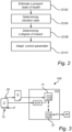
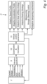
- Fig. 2 is a flow-chart of method steps of examples described herein and fig. 3 is a block diagram of a system 100.
- a present state of health, SOH, of the electrical energy storage system is estimated by a control unit 102.
- the SOH is determined from known measures but generally relates to loss in capacity relative to a capacity at the beginning of life of the battery, or the internal resistance increase of the battery relative the internal resistance at the beginning of life of the battery. Further, SOH may equally be defined of loss in range, loss in peak acceleration capability, efficiency loss, loss in power-ability etc.
- SOH is derived or calculated from current, voltage, and/or temperature measurements of the cells or packs of the electrical energy storage system. The estimated SOH is used as input to a vibration-SOH model 10 accessible by the control unit 102 in a memory 11.
- step S106 a degree of impact S of the vibrations of the electrical energy storage system 2 on the SOH of the electrical energy storage system 2 is determined by the control unit 102.
- the control unit 102 processes the determined vibration magnitude and vibration frequency spectrum in a vibration-SOH model 10 adapted to infer a relationship between vibration magnitude and vibration frequency spectrum, and SOH.
- the vibration-SOH model 10 is constructed from performing correlation between collected vibration data and the observed effect on the SOH to provide a cause-effect relationship.
- the input vibration data includes full vibration power spectrum, i.e., vibration power magnitude at various frequencies.
- other stress factors on SoH are decoupled and filtered before correlating SoH with vibration data otherwise to avoid associating all the ageing, that is, a reduction in SOH, with only vibrations.
- the input vibration data 5 and the present SOH are correlated with the corresponding states in the vibration-SOH model 10.
- the output from the correlation provides basis for quantifying the impact of the vibration on the SOH.
- step S110 at least one vehicle control parameter P is adapted by the control unit 102 to vary at least one of the vibration magnitude and the vibration frequency of the electrical energy storage system 2 to reduce the determined degree of impact of the vibrations of the electrical energy storage system.
- the vehicle control parameter may refer to many different ways of causing a counter vibration to reduce effect on the SOH caused by external vibrations.
- a speed profile of the vehicle may be adapted to reduce vibrations. Adapting the speed profile is primarily used in a cruise control mode or self-driving mode of the vehicle and related to the absolute speed for individual stretches of an entire route, the average speed along the route, or specific combinations of speeds for stretches of the route.
- an acceleration profile may be employed in a cruise control mode or self-driving mode of the vehicle.
- Other examples include a gear-shifting strategy, a braking strategy, steering control, and a dampening mechanism, of the vehicle.
- a gear shifting strategy relates to which gears to use for the transmission of the vehicle along the route to ensure reduced vibrations.
- Braking strategy includes how aggressively to use the brakes of the vehicle, and to plan each braking operation to reduce vibrations.
- Steering control relates to turning radius and speed through turns.
- Dampening mechanism may be a local dampening at the electrical energy storage 2, or a more global dampening mechanism of the vehicle chassis.
- the dampening mechanism may be a controllable local, active dampening mechanism 12, for the electrical energy storage system.
- the dampening mechanism 12 is controllable by the control unit 102 through suitable control messages.
- a vehicle component 20 is controlled by the control unit by a control message transmitted from the control unit 102 to the vehicle component 20.
- the vehicle component 20 may be drive control system such as a cruise control system.
- the adaption of the vehicle control parameters may be subject to constraints. For example, the vehicle should be allowed to arrive at the destination in a reasonable time which often means that some degree of vibrations is acceptable. Further constraints may be to arrive in-time according to a set time, ensure a predetermined driving experience, the driveability of the vehicle, passenger comfort, road speed limits, to mention a few examples.
- the vibration model 15 is continuously updated.
- a variation in vibration spectrum i.e., power magnitude and frequency
- ⁇ P adaption
- the variation and cause may be fed back to the model 15 to improve its performance.
- the vibration model is continually updated using data-driven methods to learn which part of vibration spectrum is sensitive to which vehicle control parameter. Finding this sensitivity further improves adapting the vehicle control parameter to mitigate vibrations even further.
- the vibration-SOH model 10 may be improved by correlating the variation in SOH to the variation in vibration magnitude and spectrum between consecutively acquired vibration data.
- the methods disclosed herein are suitably performed while the vehicle is travelling. Furthermore, the method steps are preferably performed in a cruise control mode or self-driving mode of the vehicle.
- S106 is determining a degree of impact of the vibrations of the electrical energy storage system on the state of health of the electrical energy storage system by processing the determined vibration magnitude and vibration frequency spectrum in a vibration-SOH model adapted to infer a relationship between vibration magnitude and vibration frequency spectrum, and state of health.
- any reference in the disclosure and/or claims to a computer system, computing system, computer device, computing device, control system, control unit, electronic control unit (ECU), processor device, etc. includes reference to one or more such devices to individually or jointly execute a set (or multiple sets) of instructions to perform any one or more of the methodologies discussed herein.
- control system may include a single control unit or a plurality of control units connected or otherwise communicatively coupled to each other, such that any performed function may be distributed between the control units as desired.
- such devices may communicate with each other or other devices by various system architectures, such as directly or via a Controller Area Network (CAN) bus, etc.
- CAN Controller Area Network
- the processor device 702 may, for example, include a general-purpose processor, an application specific processor, a Digital Signal Processor (DSP), an Application Specific Integrated Circuit (ASIC), a Field Programmable Gate Array (FPGA), a circuit containing processing components, a group of distributed processing components, a group of distributed computers configured for processing, or other programmable logic device, discrete gate or transistor logic, discrete hardware components, or any combination thereof designed to perform the functions described herein.
- the processor device may further include computer executable code that controls operation of the programmable device.
- the memory 704 may include non-volatile memory 708 (e.g., read-only memory (ROM), erasable programmable read-only memory (EPROM), electrically erasable programmable read-only memory (EEPROM), etc.), and volatile memory 710 (e.g., random-access memory (RAM)), or any other medium which can be used to carry or store desired program code in the form of machine-executable instructions or data structures and which can be accessed by a computer or other machine with a processor device 702.
- a basic input/output system (BIOS) 712 may be stored in the non-volatile memory 708 and can include the basic routines that help to transfer information between elements within the computer system 700.
- BIOS basic input/output system
- the computer system 700 also may include an input device interface 722 (e.g., input device interface and/or output device interface).
- the input device interface 722 may be configured to receive input and selections to be communicated to the computer system 700 when executing instructions, such as from a keyboard, mouse, touch-sensitive surface, etc.
- Such input devices may be connected to the processor device 702 through the input device interface 722 coupled to the system bus 706 but can be connected through other interfaces such as a parallel port, an Institute of Electrical and Electronic Engineers (IEEE) 1394 serial port, a Universal Serial Bus (USB) port, an IR interface, and the like.
- IEEE Institute of Electrical and Electronic Engineers
- USB Universal Serial Bus
Landscapes
- Engineering & Computer Science (AREA)
- Transportation (AREA)
- Mechanical Engineering (AREA)
- Power Engineering (AREA)
- Life Sciences & Earth Sciences (AREA)
- Sustainable Development (AREA)
- Sustainable Energy (AREA)
- General Physics & Mathematics (AREA)
- Physics & Mathematics (AREA)
- Chemical & Material Sciences (AREA)
- Chemical Kinetics & Catalysis (AREA)
- Electrochemistry (AREA)
- General Chemical & Material Sciences (AREA)
- Automation & Control Theory (AREA)
- Electric Propulsion And Braking For Vehicles (AREA)
- Secondary Cells (AREA)
Priority Applications (3)
| Application Number | Priority Date | Filing Date | Title |
|---|---|---|---|
| EP22214604.5A EP4389497A1 (de) | 2022-12-19 | 2022-12-19 | Verwendung von vibrationsdaten und soh-rückkopplung zur steuerung der batteriepackvibration |
| US18/537,303 US20240201279A1 (en) | 2022-12-19 | 2023-12-12 | Usage of vibration data and soh feedback for controlling battery pack vibration |
| CN202311709565.2A CN118219925A (zh) | 2022-12-19 | 2023-12-13 | 使用振动数据和soh反馈来控制电池组振动 |
Applications Claiming Priority (1)
| Application Number | Priority Date | Filing Date | Title |
|---|---|---|---|
| EP22214604.5A EP4389497A1 (de) | 2022-12-19 | 2022-12-19 | Verwendung von vibrationsdaten und soh-rückkopplung zur steuerung der batteriepackvibration |
Publications (1)
| Publication Number | Publication Date |
|---|---|
| EP4389497A1 true EP4389497A1 (de) | 2024-06-26 |
Family
ID=84537990
Family Applications (1)
| Application Number | Title | Priority Date | Filing Date |
|---|---|---|---|
| EP22214604.5A Pending EP4389497A1 (de) | 2022-12-19 | 2022-12-19 | Verwendung von vibrationsdaten und soh-rückkopplung zur steuerung der batteriepackvibration |
Country Status (3)
| Country | Link |
|---|---|
| US (1) | US20240201279A1 (de) |
| EP (1) | EP4389497A1 (de) |
| CN (1) | CN118219925A (de) |
Families Citing this family (2)
| Publication number | Priority date | Publication date | Assignee | Title |
|---|---|---|---|---|
| CN118494220B (zh) * | 2024-07-18 | 2024-09-20 | 博格华纳汽车零部件(武汉)有限公司 | 一种电动汽车整车自适应防抖控制方法及防抖调试方法 |
| CN121679376A (zh) * | 2026-02-10 | 2026-03-17 | 长沙勤凯智能科技有限公司 | 一种工程车蓄电池智能监测系统 |
Citations (4)
| Publication number | Priority date | Publication date | Assignee | Title |
|---|---|---|---|---|
| US20160221446A1 (en) * | 2013-09-12 | 2016-08-04 | Hitachi Automotive Systems, Ltd. | Driving force control device and driving force control method |
| CN108679160A (zh) * | 2018-04-09 | 2018-10-19 | 华为技术有限公司 | 一种减振装置、减振系统及减振方法 |
| CN113093041A (zh) * | 2021-04-06 | 2021-07-09 | 吴炜 | 一种新能源汽车动力系统电池健康状态远程数据采集和诊断分析系统 |
| CN113466731A (zh) * | 2021-07-29 | 2021-10-01 | 广东博力威科技股份有限公司 | 电池承受振荡最大时长的检测方法、装置、设备及介质 |
-
2022
- 2022-12-19 EP EP22214604.5A patent/EP4389497A1/de active Pending
-
2023
- 2023-12-12 US US18/537,303 patent/US20240201279A1/en active Pending
- 2023-12-13 CN CN202311709565.2A patent/CN118219925A/zh active Pending
Patent Citations (4)
| Publication number | Priority date | Publication date | Assignee | Title |
|---|---|---|---|---|
| US20160221446A1 (en) * | 2013-09-12 | 2016-08-04 | Hitachi Automotive Systems, Ltd. | Driving force control device and driving force control method |
| CN108679160A (zh) * | 2018-04-09 | 2018-10-19 | 华为技术有限公司 | 一种减振装置、减振系统及减振方法 |
| CN113093041A (zh) * | 2021-04-06 | 2021-07-09 | 吴炜 | 一种新能源汽车动力系统电池健康状态远程数据采集和诊断分析系统 |
| CN113466731A (zh) * | 2021-07-29 | 2021-10-01 | 广东博力威科技股份有限公司 | 电池承受振荡最大时长的检测方法、装置、设备及介质 |
Non-Patent Citations (1)
| Title |
|---|
| CAPOSCIUTTI GIANLUCA ET AL: "Analysis of SoH for Lithium Battery Cells operating under Vibration Stress", 2020 IEEE 7TH INTERNATIONAL WORKSHOP ON METROLOGY FOR AEROSPACE (METROAEROSPACE), IEEE, 22 June 2020 (2020-06-22), pages 72 - 77, XP033802038, DOI: 10.1109/METROAEROSPACE48742.2020.9160101 * |
Also Published As
| Publication number | Publication date |
|---|---|
| CN118219925A (zh) | 2024-06-21 |
| US20240201279A1 (en) | 2024-06-20 |
Similar Documents
| Publication | Publication Date | Title |
|---|---|---|
| US8983752B2 (en) | System and method for identifying characteristics of a vehicle | |
| US20240201279A1 (en) | Usage of vibration data and soh feedback for controlling battery pack vibration | |
| US8612079B2 (en) | Optimizing system performance using state of health information | |
| US20140121956A1 (en) | System and method for range calculation in vehicles | |
| CN107037370B (zh) | 基于监控数据的电动汽车剩余电量计算方法 | |
| CN104859472B (zh) | 用于车辆的动力传动系控制系统、车辆及控制车辆的方法 | |
| US8994340B2 (en) | Cell temperature and degradation measurement in lithium ion battery systems using cell voltage and pack current measurement and the relation of cell impedance to temperature based on signal given by the power inverter | |
| US9132745B1 (en) | Frequency based battery model parameter estimation | |
| CN113740753A (zh) | 根据电蓄能器的预测老化状态来运行电可驱动机动车的方法和设备 | |
| US10436845B2 (en) | Electric vehicle battery monitoring system | |
| DE102015110857A1 (de) | Restreichweitenprognose mit Kompensation von Änderung der Bewegungsenergie | |
| US20150251555A1 (en) | Parameter identification offloading using cloud computing resources | |
| US20240200971A1 (en) | Usage of vibration data for route planning and extending battery pack lifetime | |
| CN103661394A (zh) | 道路坡度估计仲裁 | |
| US11275107B2 (en) | Method and apparatus for monitoring isolation of an electric power bus | |
| KR20190103236A (ko) | 배터리 팩의 충전 상태를 결정하기 위한 방법 및 장치 | |
| CN112600263B (zh) | 用于电池单体充电平衡的方法和设备 | |
| WO2016140152A1 (ja) | 電池制御装置、および、車両システム | |
| CN105128853A (zh) | 一种用于计算增程式混合动力汽车续驶里程的系统 | |
| US20150197158A1 (en) | Perturbative injection for battery parameter identification | |
| US20240001800A1 (en) | Method and system for determining an electrical energy storage pack replacement configuration | |
| WO2024133249A1 (en) | System and method for improving utilization of electrical energy storage packs | |
| US20240133969A1 (en) | Method and system for reconfiguring an electrical energy storage system comprising multiple electrical energy storage packs | |
| WO2015166926A1 (ja) | リチウムイオン二次電池システム、および、リチウムイオン二次電池の劣化診断方法 | |
| EP3048450B1 (de) | System und Verfahren zur Bestimmung der Verbrauchsgrenzen einer Batterie |
Legal Events
| Date | Code | Title | Description |
|---|---|---|---|
| PUAI | Public reference made under article 153(3) epc to a published international application that has entered the european phase |
Free format text: ORIGINAL CODE: 0009012 |
|
| STAA | Information on the status of an ep patent application or granted ep patent |
Free format text: STATUS: THE APPLICATION HAS BEEN PUBLISHED |
|
| AK | Designated contracting states |
Kind code of ref document: A1 Designated state(s): AL AT BE BG CH CY CZ DE DK EE ES FI FR GB GR HR HU IE IS IT LI LT LU LV MC ME MK MT NL NO PL PT RO RS SE SI SK SM TR |
|
| STAA | Information on the status of an ep patent application or granted ep patent |
Free format text: STATUS: REQUEST FOR EXAMINATION WAS MADE |
|
| 17P | Request for examination filed |
Effective date: 20241202 |
|
| RBV | Designated contracting states (corrected) |
Designated state(s): AL AT BE BG CH CY CZ DE DK EE ES FI FR GB GR HR HU IE IS IT LI LT LU LV MC ME MK MT NL NO PL PT RO RS SE SI SK SM TR |