EP4389571A1 - Mobilitätsvorrichtung zur innen- und aussenverwendung - Google Patents
Mobilitätsvorrichtung zur innen- und aussenverwendung Download PDFInfo
- Publication number
- EP4389571A1 EP4389571A1 EP23216075.4A EP23216075A EP4389571A1 EP 4389571 A1 EP4389571 A1 EP 4389571A1 EP 23216075 A EP23216075 A EP 23216075A EP 4389571 A1 EP4389571 A1 EP 4389571A1
- Authority
- EP
- European Patent Office
- Prior art keywords
- support means
- mobility device
- mobility
- rear wheel
- machine
- Prior art date
- Legal status (The legal status is an assumption and is not a legal conclusion. Google has not performed a legal analysis and makes no representation as to the accuracy of the status listed.)
- Pending
Links
Images

Classifications
-
- B—PERFORMING OPERATIONS; TRANSPORTING
- B62—LAND VEHICLES FOR TRAVELLING OTHERWISE THAN ON RAILS
- B62H—CYCLE STANDS; SUPPORTS OR HOLDERS FOR PARKING OR STORING CYCLES; APPLIANCES PREVENTING OR INDICATING UNAUTHORIZED USE OR THEFT OF CYCLES; LOCKS INTEGRAL WITH CYCLES; DEVICES FOR LEARNING TO RIDE CYCLES
- B62H1/00—Supports or stands forming part of or attached to cycles
- B62H1/02—Articulated stands, e.g. in the shape of hinged arms
- B62H1/04—Substantially U-shaped stands for embracing the rear wheel
-
- A—HUMAN NECESSITIES
- A63—SPORTS; GAMES; AMUSEMENTS
- A63B—APPARATUS FOR PHYSICAL TRAINING, GYMNASTICS, SWIMMING, CLIMBING, OR FENCING; BALL GAMES; TRAINING EQUIPMENT
- A63B21/00—Exercising apparatus for developing or strengthening the muscles or joints of the body by working against a counterforce, with or without measuring devices
- A63B21/005—Exercising apparatus for developing or strengthening the muscles or joints of the body by working against a counterforce, with or without measuring devices using electromagnetic or electric force-resisters
- A63B21/0058—Exercising apparatus for developing or strengthening the muscles or joints of the body by working against a counterforce, with or without measuring devices using electromagnetic or electric force-resisters using motors
-
- A—HUMAN NECESSITIES
- A63—SPORTS; GAMES; AMUSEMENTS
- A63B—APPARATUS FOR PHYSICAL TRAINING, GYMNASTICS, SWIMMING, CLIMBING, OR FENCING; BALL GAMES; TRAINING EQUIPMENT
- A63B69/00—Training appliances or apparatus for special sports
- A63B69/16—Training appliances or apparatus for special sports for cycling, i.e. arrangements on or for real bicycles
-
- B—PERFORMING OPERATIONS; TRANSPORTING
- B62—LAND VEHICLES FOR TRAVELLING OTHERWISE THAN ON RAILS
- B62J—CYCLE SADDLES OR SEATS; AUXILIARY DEVICES OR ACCESSORIES SPECIALLY ADAPTED TO CYCLES AND NOT OTHERWISE PROVIDED FOR, e.g. ARTICLE CARRIERS OR CYCLE PROTECTORS
- B62J7/00—Luggage carriers
- B62J7/02—Luggage carriers characterised by the arrangement thereof on cycles
- B62J7/04—Luggage carriers characterised by the arrangement thereof on cycles arranged above or behind the rear wheel
-
- B—PERFORMING OPERATIONS; TRANSPORTING
- B62—LAND VEHICLES FOR TRAVELLING OTHERWISE THAN ON RAILS
- B62K—CYCLES; CYCLE FRAMES; CYCLE STEERING DEVICES; RIDER-OPERATED TERMINAL CONTROLS SPECIALLY ADAPTED FOR CYCLES; CYCLE AXLE SUSPENSIONS; CYCLE SIDECARS, FORECARS, OR THE LIKE
- B62K13/00—Cycles convertible to, or transformable into, other types of cycles or land vehicle
-
- B—PERFORMING OPERATIONS; TRANSPORTING
- B62—LAND VEHICLES FOR TRAVELLING OTHERWISE THAN ON RAILS
- B62M—RIDER PROPULSION OF WHEELED VEHICLES OR SLEDGES; POWERED PROPULSION OF SLEDGES OR SINGLE-TRACK CYCLES; TRANSMISSIONS SPECIALLY ADAPTED FOR SUCH VEHICLES
- B62M6/00—Rider propulsion of wheeled vehicles with additional source of power, e.g. combustion engine or electric motor
- B62M6/40—Rider propelled cycles with auxiliary electric motor
-
- A—HUMAN NECESSITIES
- A63—SPORTS; GAMES; AMUSEMENTS
- A63B—APPARATUS FOR PHYSICAL TRAINING, GYMNASTICS, SWIMMING, CLIMBING, OR FENCING; BALL GAMES; TRAINING EQUIPMENT
- A63B69/00—Training appliances or apparatus for special sports
- A63B69/16—Training appliances or apparatus for special sports for cycling, i.e. arrangements on or for real bicycles
- A63B2069/164—Training appliances or apparatus for special sports for cycling, i.e. arrangements on or for real bicycles supports for the rear of the bicycle, e.g. for the rear forks
- A63B2069/165—Training appliances or apparatus for special sports for cycling, i.e. arrangements on or for real bicycles supports for the rear of the bicycle, e.g. for the rear forks rear wheel hub supports
Definitions
- the present invention relates to the field of electrically assisted mobility devices, and more particularly an electrically assisted bicycle usable on the move or statically, indoors and outdoors.
- This type of machine includes a rechargeable battery in the conventional manner with, for example, a connection cable to an electrical network.
- the present invention therefore aims to overcome one or more of the drawbacks of the devices of the prior art by proposing a mobility device that can be used on the move or statically, outdoors and indoors, with an improved battery charging device.
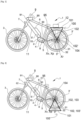
- FIG. 1 illustrates a mobility device 1 according to the invention.
- the machine 1 here is an electrically assisted bicycle comprising an electric motor 2.
- the electric motor 2 is arranged to provide part of the propulsion of the machine.
- the machine 1 comprises a seating means 95 for the user, of the saddle type, and a steering means 9, of the handlebar type.
- the machine 1 comprises at least two wheels 3, 3 'to which a driving force is supplied, via two pedals or equivalent rotating around a crank axle of axis Xp which drives the rear wheel 3' for example by a chain, or any other means of transmission during its use.
- the rear wheel 3' is the one positioned opposite the handlebar 9, as opposed to the front wheel 3, which is positioned at the level of the handlebar 9 of the mobility machine 1.
- the machine 1 also includes a control unit 4 as well as several sensors 5, 5', 5", located for example at the level of the crankset, on the frame 11 of the machine 1 or at the level of a wheel 3, 3 '.
- the machine 1 shown here also includes an energy storage device in the form of a battery 6, a lighting system 7, a pedal board 8 with axis Xp, a location and/or navigation system 90 as well as a man-machine interface system 91 comprising in particular a touch screen capable of displaying information for and/or taking into account the requests of said user.
- the man-machine interface system 91 is in particular connected to the location system 90 and serves as a navigation interface.
- the invention is not limited to a particular man-machine interface system, and can include any system known to those skilled in the art.
- the wheels 3, 3' are provided with a braking system 31, including disc brakes 32.
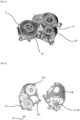
- the machine 1 comprises a transmission assembly 10 formed by a speed change device 20 and the electric motor 2, visible [ Fig. 3 ], to provide part of the power for the propulsion of machine 1.
- the transmission assembly 10 is at least partly housed in a housing 30 closed by a cover 316 (illustrated [ Fig. 4 ]) here positioned at level of the crankset 8 whose axis Xp coincides with the output axis X v of the speed change device 20.
- the housing comprises a first housing 311 arranged to house the gears of the gear change device 20 and at least two housings 312, 313 distinct from each other, others arranged to respectively house the electric motor and the gear shift actuator.
- the housing 30 is open on one side.
- this face is closed by a cover 316.
- the gear change device 20 has at least 2 gears, and for example 7 gears.
- the speed change device 20 comprises a series of seven output pinions 60 of axis of reference FR 1 to FR 7 arranged to rotate freely around a selection shaft 40.
- the selection tree 40 illustrated [ Fig. 6 ] houses a shuttle 41 surrounding a endless screw 21 of the speed change device 20.
- the speed change device 20 comprises an epicyclic gear train.
- the machine 1 comprises a speed change actuator 70 arranged to move the shuttle 41 along the endless screw 21 by a helical kinematic connection, between at least 2 positions and for example between 7 positions of P 1 to P 7 and engage a selected gear.
- the gear change actuator 70 comprises electrical means for moving the shuttle 41, in the form of a geared motor. This includes a motor 81 and a reduction gear 82.
- the geared motor also comprises a pinion 22 on the axis of the endless screw 21, an intermediate pinion 22' and a pinion 22' on the axis Xm of the motor 81.
- the teeth of the pinion 22, 22', 22" can be straight as illustrated or helical in a variant not illustrated.
- the gear change actuator 70 has a belt or a chain or a universal joint or sprockets.
- the rotational guidance of the endless screw 21 is for example ensured using bearings at each of its ends.
- the shuttle 41 when a speed is selected, the shuttle 41 is configured to, during its movement, position itself under the pinion of the selected gear, and engage this gear.
- the shuttle 41 When using the machine while moving, the shuttle 41 makes it possible to select the chosen gear which will engage an input pinion Fri via a pawl 42.
- the input gear Fri then meshes with an output gear Fi.
- a stop at each end limits the movement of the shuttle 41.
- the movement of the shuttle is controlled by a position sensor.
- the mobility device 1 comprises pivoting support means 100.
- the pivoting support means 100 are formed by a luggage rack.
- the support means 100 are formed by at least one rectangular frame, from which at least 2 fixing bars 102, 103 extend, arranged on either side of the rear wheel 3'. .
- the fixing bars 102, 103 extend so as to allow the fixing of the support means 100 to the frame 11 of the mobility machine 1, at the level of the rear wheel 3'.
- the support means 100 comprise 4 fixing bars 102, 102', 103, 103' arranged 2 by 2 on either side of the rear wheel 3'.
- the 2 bars arranged on the same side of the wheel 3' are fixed in the same place at the level of the wheel 3', and for example on the frame 11.
- the bars are fixed to the frame 11 of the mobility machine at the center of the rear wheel 3'.
- the pivoting support means 100 are thus fixed at the level of the center of the rear wheel 3', on either side of the wheel 3' via the fixing bars.
- the support means 100 are fixed so as to leave the rear wheel 3' free to rotate whatever the position of the pivoting support means 100.
- the fixing between the fixing bars and the center of the wheel is carried out with a fixing element 101 allowing the rotation of the pivoting support means 100 around the rear wheel 3'.
- the support means 100 are movable in rotation around the axis Xr of the rear wheel 3' to move from a position where they are arranged above the rear wheel 3' to a position below the rear wheel 3'.
- the top and bottom are defined in relation to the ground on which the mobility machine 1 is placed.
- the underside is the area facing the ground.
- pivoting support means 100 are positioned and locked in rotation above the rear wheel 3' [ Fig. 1 ], or the pivoting support means are positioned and locked in rotation below the rear wheel 3' [ fig. 2 ].
- the fixing element 101 is formed by a screw. According to one embodiment of the invention, the fixing element 101 is formed by an eccentric clamping type system.
- the support means are positioned and locked in rotation below the rear wheel 3', the mobility machine 1 is propelled by the driving force of the user and by the electric motor.
- the user accelerates or slows down, uses automatic speed mode or not.
- the pivoting support means are used as a luggage rack, as illustrated figure 1 , and allow the transport of element 12 of the parcel type, luggage, child seat, etc. or any other transportable elements on a luggage rack of such a mobility machine 1.
- This mode of use uses the power of the battery, without allowing it to be recharged.
- the pivoting support means 100 are positioned and locked in rotation below the rear wheel 3 [Fi. 2].
- the rear wheel 3' of machine 1 is then not in contact with the ground.
- the driving of the rear wheel 3' by the user or by the motor thus does not set the machine 1 in motion.
- the machine is then used as an indoor bike and allows for sporting exercises.
- the motor 2 is used to send a resistance force to the pedals.
- the user pedals and must exert a force greater than that sent by the motor to rotate the bottom bracket axle.
- the force is adjusted according to several operating modes depending on user needs and/or predefined parameters.
- the pedal not being used to propel the machine 1 the power transmitted by the user by pressing the pedal is used to recharge the battery.
- a torque less than zero is applied to the electric motor 2. This creates resistance for the user who will then drive the motor by pedaling. The energy generated by the user while pedaling is then stored in the battery. This energy is then used, for example, for the first mode of use of the mobility machine 1.
- the energy is stored in the battery by storage means 61 via power cables 62.
- the battery can be recharged either via the power cable 62 from a standard energy source coming from from the electrical network, or via the power cables 62 from the storage means 61 of the machine 1.
Landscapes
- Engineering & Computer Science (AREA)
- Mechanical Engineering (AREA)
- Health & Medical Sciences (AREA)
- General Health & Medical Sciences (AREA)
- Physical Education & Sports Medicine (AREA)
- Chemical & Material Sciences (AREA)
- Combustion & Propulsion (AREA)
- Biophysics (AREA)
- Orthopedic Medicine & Surgery (AREA)
- Physics & Mathematics (AREA)
- Life Sciences & Earth Sciences (AREA)
- Electromagnetism (AREA)
- Transportation (AREA)
- Handcart (AREA)
Applications Claiming Priority (1)
| Application Number | Priority Date | Filing Date | Title |
|---|---|---|---|
| IN202241074027 | 2022-12-20 |
Publications (1)
| Publication Number | Publication Date |
|---|---|
| EP4389571A1 true EP4389571A1 (de) | 2024-06-26 |
Family
ID=89222318
Family Applications (1)
| Application Number | Title | Priority Date | Filing Date |
|---|---|---|---|
| EP23216075.4A Pending EP4389571A1 (de) | 2022-12-20 | 2023-12-12 | Mobilitätsvorrichtung zur innen- und aussenverwendung |
Country Status (1)
| Country | Link |
|---|---|
| EP (1) | EP4389571A1 (de) |
Citations (3)
| Publication number | Priority date | Publication date | Assignee | Title |
|---|---|---|---|---|
| EP0905014B1 (de) * | 1997-09-30 | 2004-06-02 | Honda Giken Kogyo Kabushiki Kaisha | Motorangetriebenes Fahrrad |
| NL1031583C2 (nl) * | 2006-04-12 | 2007-10-15 | Giant Mfg Co | Rijwiel met zwenkbare, als bagagedrager en als standaard bruikbare steuneenheid. |
| DE102012012270A1 (de) * | 2012-06-21 | 2012-12-20 | Daimler Ag | Elektrofahrrad und eine Trainingsvorrichtung für ein solches Elektrofahrrad |
-
2023
- 2023-12-12 EP EP23216075.4A patent/EP4389571A1/de active Pending
Patent Citations (3)
| Publication number | Priority date | Publication date | Assignee | Title |
|---|---|---|---|---|
| EP0905014B1 (de) * | 1997-09-30 | 2004-06-02 | Honda Giken Kogyo Kabushiki Kaisha | Motorangetriebenes Fahrrad |
| NL1031583C2 (nl) * | 2006-04-12 | 2007-10-15 | Giant Mfg Co | Rijwiel met zwenkbare, als bagagedrager en als standaard bruikbare steuneenheid. |
| DE102012012270A1 (de) * | 2012-06-21 | 2012-12-20 | Daimler Ag | Elektrofahrrad und eine Trainingsvorrichtung für ein solches Elektrofahrrad |
Non-Patent Citations (1)
| Title |
|---|
| YOUTUBE FACEBOOK ET AL: "Electronic Shifter Unit for E-Bikes equipped with Rohloff SPEEDHUB", 1 January 2017 (2017-01-01), XP093349888, Retrieved from the Internet <URL:https://www.rohloff.de/en/products/speedhub/e-14#:~:text=Holding%20the%20button%20down%20initiates,back%20into%20the%20starting%20gear.> [retrieved on 20260105] * |
Similar Documents
| Publication | Publication Date | Title |
|---|---|---|
| EP3676166B1 (de) | Antriebsstrang | |
| EP3323705B1 (de) | Motorantriebsanlage | |
| BE1026057B1 (fr) | Groupe motopropulseur pour véhicule à pédales | |
| FR2692850A1 (fr) | Dispositif de commande de changement de vitesses équipant un véhicule. | |
| CA3212579A1 (fr) | Dispositif de changement de vitesse et engin de mobilite associe | |
| WO2022207663A1 (fr) | Dispositif de changement de vitesse simplifié et engin de mobilité associé | |
| WO2022112506A1 (fr) | Dispositif de changement de vitesse et engin de mobilité associé | |
| WO1995026900A1 (fr) | Dispositif de selection de rapports pour engins mus par la force musculaire, notamment pour bicyclette | |
| EP4389571A1 (de) | Mobilitätsvorrichtung zur innen- und aussenverwendung | |
| FR3143538A1 (fr) | Engin de mobilité à assistance électrique | |
| WO2013092301A1 (fr) | Moyeu motorisé pour la motorisation électrique d'un essieu d'un véhicule automobile à traction hybride | |
| EP4584515A1 (de) | Gangschaltvorrichtung für ein mobilitätsfahrzeug | |
| FR3116801A1 (fr) | Ensemble de transmission pour engin de mobilité et procédé | |
| EP4545393B1 (de) | Schaltvorrichtung und mobilitätsvorrichtung dafür | |
| WO2017072422A1 (fr) | Dispositif d'assistance motorise, notamment au pédalage, et cycle associe | |
| WO2025087996A1 (fr) | Dispositif de changement de vitesse et engin de mobilité associé | |
| FR3163636A1 (fr) | Groupe motopropulseur a transmission continument variable et a reducteur epicycloidal | |
| FR3111112A1 (fr) | Système de transmission à assistance motorisée pour vélo et vélo équipé dudit système | |
| FR3155204A1 (fr) | Système de fermeture pour ensemble de transmission et engin de mobilité associé. | |
| EP4506589A1 (de) | Schaltvorrichtung und mobilitätsvorrichtung dafür | |
| FR3154694A1 (fr) | Dispositif de changement de vitesse et engin de mobilité associé. | |
| FR3164970A1 (fr) | Système de fermeture renforcé pour ensemble de transmission et engin de mobilité associé. | |
| FR3013311A1 (fr) | Electro bike kit de moteur electrique pour tous types de velos traditionnel et vtt | |
| FR3155203A1 (fr) | Système de fermeture pour ensemble de transmission et engin de mobilité associé. | |
| FR3152013A1 (fr) | Dispositif de changement de vitesse et engin de mobilité associé. |
Legal Events
| Date | Code | Title | Description |
|---|---|---|---|
| PUAI | Public reference made under article 153(3) epc to a published international application that has entered the european phase |
Free format text: ORIGINAL CODE: 0009012 |
|
| STAA | Information on the status of an ep patent application or granted ep patent |
Free format text: STATUS: REQUEST FOR EXAMINATION WAS MADE |
|
| 17P | Request for examination filed |
Effective date: 20231212 |
|
| AK | Designated contracting states |
Kind code of ref document: A1 Designated state(s): AL AT BE BG CH CY CZ DE DK EE ES FI FR GB GR HR HU IE IS IT LI LT LU LV MC ME MK MT NL NO PL PT RO RS SE SI SK SM TR |
|
| STAA | Information on the status of an ep patent application or granted ep patent |
Free format text: STATUS: EXAMINATION IS IN PROGRESS |
|
| 17Q | First examination report despatched |
Effective date: 20260112 |