EP4389601A1 - Wasserversorgungs- und -verteilungssystem an bord eines flugzeugs und verfahren zum betrieb solch eines systems - Google Patents
Wasserversorgungs- und -verteilungssystem an bord eines flugzeugs und verfahren zum betrieb solch eines systems Download PDFInfo
- Publication number
- EP4389601A1 EP4389601A1 EP22215097.1A EP22215097A EP4389601A1 EP 4389601 A1 EP4389601 A1 EP 4389601A1 EP 22215097 A EP22215097 A EP 22215097A EP 4389601 A1 EP4389601 A1 EP 4389601A1
- Authority
- EP
- European Patent Office
- Prior art keywords
- consumer
- conduit system
- water
- pressure
- pressure conduit
- Prior art date
- Legal status (The legal status is an assumption and is not a legal conclusion. Google has not performed a legal analysis and makes no representation as to the accuracy of the status listed.)
- Pending
Links
Images


Classifications
-
- E—FIXED CONSTRUCTIONS
- E03—WATER SUPPLY; SEWERAGE
- E03B—INSTALLATIONS OR METHODS FOR OBTAINING, COLLECTING, OR DISTRIBUTING WATER
- E03B1/00—Methods or layout of installations for water supply
- E03B1/04—Methods or layout of installations for water supply for domestic or like local supply
-
- B—PERFORMING OPERATIONS; TRANSPORTING
- B64—AIRCRAFT; AVIATION; COSMONAUTICS
- B64D—EQUIPMENT FOR FITTING IN OR TO AIRCRAFT; FLIGHT SUITS; PARACHUTES; ARRANGEMENT OR MOUNTING OF POWER PLANTS OR PROPULSION TRANSMISSIONS IN AIRCRAFT
- B64D11/00—Passenger or crew accommodation; Flight-deck installations not otherwise provided for
- B64D11/04—Galleys
-
- B—PERFORMING OPERATIONS; TRANSPORTING
- B64—AIRCRAFT; AVIATION; COSMONAUTICS
- B64F—GROUND OR AIRCRAFT-CARRIER-DECK INSTALLATIONS SPECIALLY ADAPTED FOR USE IN CONNECTION WITH AIRCRAFT; DESIGNING, MANUFACTURING, ASSEMBLING, CLEANING, MAINTAINING OR REPAIRING AIRCRAFT, NOT OTHERWISE PROVIDED FOR; HANDLING, TRANSPORTING, TESTING OR INSPECTING AIRCRAFT COMPONENTS, NOT OTHERWISE PROVIDED FOR
- B64F5/00—Designing, manufacturing, assembling, cleaning, maintaining or repairing aircraft, not otherwise provided for; Handling, transporting, testing or inspecting aircraft components, not otherwise provided for
- B64F5/40—Maintaining or repairing aircraft
-
- E—FIXED CONSTRUCTIONS
- E03—WATER SUPPLY; SEWERAGE
- E03B—INSTALLATIONS OR METHODS FOR OBTAINING, COLLECTING, OR DISTRIBUTING WATER
- E03B11/00—Arrangements or adaptations of tanks for water supply
- E03B11/02—Arrangements or adaptations of tanks for water supply for domestic or like local water supply
- E03B11/06—Arrangements or adaptations of tanks for water supply for domestic or like local water supply with air regulators
-
- E—FIXED CONSTRUCTIONS
- E03—WATER SUPPLY; SEWERAGE
- E03B—INSTALLATIONS OR METHODS FOR OBTAINING, COLLECTING, OR DISTRIBUTING WATER
- E03B7/00—Water main or service pipe systems
- E03B7/003—Arrangement for testing of watertightness of water supply conduits
-
- E—FIXED CONSTRUCTIONS
- E03—WATER SUPPLY; SEWERAGE
- E03B—INSTALLATIONS OR METHODS FOR OBTAINING, COLLECTING, OR DISTRIBUTING WATER
- E03B7/00—Water main or service pipe systems
- E03B7/04—Domestic or like local pipe systems
-
- E—FIXED CONSTRUCTIONS
- E03—WATER SUPPLY; SEWERAGE
- E03B—INSTALLATIONS OR METHODS FOR OBTAINING, COLLECTING, OR DISTRIBUTING WATER
- E03B7/00—Water main or service pipe systems
- E03B7/07—Arrangement of devices, e.g. filters, flow controls, measuring devices, siphons or valves, in the pipe systems
- E03B7/075—Arrangement of devices for control of pressure or flow rate
-
- E—FIXED CONSTRUCTIONS
- E03—WATER SUPPLY; SEWERAGE
- E03B—INSTALLATIONS OR METHODS FOR OBTAINING, COLLECTING, OR DISTRIBUTING WATER
- E03B7/00—Water main or service pipe systems
- E03B7/07—Arrangement of devices, e.g. filters, flow controls, measuring devices, siphons or valves, in the pipe systems
- E03B7/08—Arrangement of draining devices, e.g. manual shut-off valves
-
- E—FIXED CONSTRUCTIONS
- E03—WATER SUPPLY; SEWERAGE
- E03D—WATER-CLOSETS OR URINALS WITH FLUSHING DEVICES; FLUSHING VALVES THEREFOR
- E03D3/00—Flushing devices operated by pressure of the water supply system flushing valves not connected to the water-supply main, also if air is blown in the water seal for a quick flushing
- E03D3/10—Flushing devices with pressure-operated reservoir, e.g. air chamber
-
- E—FIXED CONSTRUCTIONS
- E03—WATER SUPPLY; SEWERAGE
- E03D—WATER-CLOSETS OR URINALS WITH FLUSHING DEVICES; FLUSHING VALVES THEREFOR
- E03D5/00—Special constructions of flushing devices, e.g. closed flushing system
- E03D5/02—Special constructions of flushing devices, e.g. closed flushing system operated mechanically or hydraulically (or pneumatically) also details such as push buttons, levers and pull-card therefor
- E03D5/024—Operated hydraulically or pneumatically
-
- G—PHYSICS
- G01—MEASURING; TESTING
- G01M—TESTING STATIC OR DYNAMIC BALANCE OF MACHINES OR STRUCTURES; TESTING OF STRUCTURES OR APPARATUS, NOT OTHERWISE PROVIDED FOR
- G01M3/00—Investigating fluid-tightness of structures
- G01M3/02—Investigating fluid-tightness of structures by using fluid or vacuum
- G01M3/26—Investigating fluid-tightness of structures by using fluid or vacuum by measuring rate of loss or gain of fluid, e.g. by pressure-responsive devices, by flow detectors
- G01M3/28—Investigating fluid-tightness of structures by using fluid or vacuum by measuring rate of loss or gain of fluid, e.g. by pressure-responsive devices, by flow detectors for pipes, cables or tubes; for pipe joints or seals; for valves ; for welds
- G01M3/2807—Investigating fluid-tightness of structures by using fluid or vacuum by measuring rate of loss or gain of fluid, e.g. by pressure-responsive devices, by flow detectors for pipes, cables or tubes; for pipe joints or seals; for valves ; for welds for pipes
- G01M3/2815—Investigating fluid-tightness of structures by using fluid or vacuum by measuring rate of loss or gain of fluid, e.g. by pressure-responsive devices, by flow detectors for pipes, cables or tubes; for pipe joints or seals; for valves ; for welds for pipes using pressure measurements
-
- G—PHYSICS
- G05—CONTROLLING; REGULATING
- G05D—SYSTEMS FOR CONTROLLING OR REGULATING NON-ELECTRIC VARIABLES
- G05D16/00—Control of fluid pressure
- G05D16/028—Controlling a pressure difference
-
- B—PERFORMING OPERATIONS; TRANSPORTING
- B64—AIRCRAFT; AVIATION; COSMONAUTICS
- B64D—EQUIPMENT FOR FITTING IN OR TO AIRCRAFT; FLIGHT SUITS; PARACHUTES; ARRANGEMENT OR MOUNTING OF POWER PLANTS OR PROPULSION TRANSMISSIONS IN AIRCRAFT
- B64D11/00—Passenger or crew accommodation; Flight-deck installations not otherwise provided for
- B64D11/02—Toilet fittings
Definitions
- the present invention is directed to a method for operating a water supply and distribution system on-board an aircraft.
- the invention is further directed to a water supply and distribution system and an aircraft comprising such system.
- Conventional water supply and distribution systems on-board commercial aircraft comprise pipework made from rigid pipes, i.e., rigid plumbing. Through the rigid pipes potable water is supplied from a central water tank towards consumer assemblies such as sinks and toilets in a lavatory or steam ovens and sinks in a galley.
- leaking water can, for example, damage sensitive electronic equipment which is especially critical regarding safety when the avionics bay is affected, because this area houses the flight control computers.
- large amounts of water mean a lot of weight, which can have a safety-relevance since it results in a shift in the center of gravity.
- an ice shell can form in the aircraft jge over several legs, which can have a mass of several hundred kilograms.
- a the system comprising a central water tank, a central pump, having an upstream side and a downstream side and being capable of conveying and pressurizing water from the upstream side to the downstream side, a plurality of consumer assemblies, each consumer assembly comprising a supply device, such as a water faucet, toilet rinse valve in a lavatory or a sink and a steam oven in a galley, and each consumer assembly being configured to supply water via the supply device, and a high-pressure conduit system, wherein the central water tank is connected to the upstream side, wherein the high-pressure conduit system connects the downstream side with the plurality of consumer assemblies, with the high-pressure conduit system being configured such that the central pump, when operating is capable of delivering water from the downstream side to the consumer assemblies, the method comprising the following steps:
- the method of the present invention is performed with a pressurized on-board water supply and distribution system as known from the prior art and comprising a central water tank, a central pump and a plurality of consumer assemblies comprising a buffer tank and a supply device. Further, the consumer assemblies are connected with the central pump via a high-pressure conduit system.
- the central pump is provided with a backflow prevention mechanism, which prevents water and/or a gas to flow in an opposite direction from the downstream side to the upstream side when it is not operated, or an additional backflow prevention valve is provided which is closed, when the central pump is not operated and prevents water and/or a gas to flow from the downstream side to the upstream side.
- the high-pressure conduit system comprises a pressure reservoir that is configured such that it applies a pressure at a reservoir pressure to the high-pressure conduit system after the operation of the central pump has been stopped with the reservoir pressure and the pressure in the high-pressure conduit system at that point in time where the central pump was stopped being the same.
- Such pressure reservoir may be in the form of a tank containing a gas volume and an elastic membrane that separates the gas volume from a further volume being connected to the high-pressure conduit system and receiving water and/or gas such as ambient air from the conduit system, i.e., the reservoir is configured in a similar form as in conventional compressors.
- a component of the high-pressure conduit system having compressibility such the aforementioned pressure reservoir can also be generated by providing shape elasticity of a hose element of the high-pressure conduit system or other compressible elements with spring properties may be integrated into the high-pressure conduit system.
- the central pump is operated such that the water in the high-pressure conduit system is pressurized to a predetermined first pressure.
- the consumer assemblies are operated such that in each of the consumer assemblies the connection between the buffer tank of the consumer assembly and the high-pressure conduit system is in a closed position.
- a first failure signal is provided in parallel the pressure in the high-pressure conduit system.
- the provision of a failure signal may be in such a form that the control unit of the on-board water supply and distribution system generates such first failure signal which is then further provided to the aircraft data network of the aircraft in which the entire system is installed.
- a specific failure message may be displayed on control panels such as the flight attendant panel and / or the first failure signal will cause that the central pump of the water supply and distribution system will automatically be switched off.
- a test-passed signal will be generated by the control unit which signal may cause that corresponding message will be displayed on the aforementioned panels. It is further preferred that this information is also stored onboard in the aircraft data base. This offers evidence for the maintenance staff when the system was tested successfully and when the system started to have a water leakage.
- a drop of the water pressure in the high-pressure conduit system below the predetermined second pressure indicates that there is a leak in the high-pressure conduit system, i.e., with this procedure it can simply be determined whether there is a leak in the high-pressure conduit system.
- water cannot escape from the high-pressure conduit system except there is a leak, so that in case the entire system is properly working, the water pressure in the system should remain constant above a certain level after an equilibrium level has been reached.
- the method of the present invention allows for quickly obtaining general information about the status of the water supply and distribution system without the need to disassembly components of a cladding or floor and to visually inspect the system.
- the inlet valves of consumer assemblies connecting the high-pressure conduit system with the inlet of the buffer tanks are kept in a closed position and the gas, preferably ambient air, in the high-pressure conduit system is pressurized, preferably by means of the central pump, until a predetermined third pressure is reached which may deviate from the first pressure but may also have the same level.
- the high pressure conduit system as well as the central tank need to be drained.
- means other than the central pump may by employed as the source for pressurized gas.
- a ground pressure source is used or that the high-pressure conduit system is configured such that it comprises an interface which can connected to an interface of the cabin pressurization system or, as an alternative, it may also be connected to an interface of the bleed air system.
- the pressure in the high-pressure conduit system is monitored for a second period of time, and in case the pressure in the high-pressure conduit system drops below a predetermined fourth pressure level within that period of time, a second failure signal is provided.
- the second failure signal may be provided the same way as in the case of the first failure signal, i.e., it may be in the form of a failure message to be transmitted through the aircraft data network, and it may also affect that the central pump is automatically switched off.
- a test-passed signal is transmitted through the aircraft data network.
- This second test with the inlet valves being in the closed position indicates that the high-pressure conduit system has a leak, when a pressure drop below the fourth pressure level is determined within the second period of time.
- this test may either be used to double check whether the high-pressure conduit system is operating properly or it can be employed as a supplementary test to be conducted when the method discussed before delivers the first failure signal.
- the method further comprises the following steps:
- the method further comprises the following steps:
- the flow through the central pump is analysed so that the flow through the pump is used as an alternative or supplementary criterion whether the supply pipe to the central pump or conduits in the high-pressure conduit system are blocked at least to a certain extent which would slow down the pressure build-up and the flow through the pump.
- the flow of water can be measured by means of a flow sensor or inverse methods can be used for example the rotational speed of a pump can be used to derive the flow if the pressure is measured by means of a pressure sensor downstream the pump.
- At least one of the plurality of consumer assemblies comprises a buffer tank connected to the high-pressure conduit system and the at least one consumer assembly being configured to supply water from the buffer tank via the supply device, and the method further comprises the following steps:
- a fourth failure signal may be transmitted, e.g., via the aircraft data network.
- a test-passed signal may again be generated and transmitted via the aircraft data network.
- the method of the present invention comprises the step of monitoring the flow of water from the upstream side to the downstream side and into the high-pressure conduit system wherein the predetermined fifth period of time is calculated based on the monitored flow of water from the upstream side to the downstream side and into the high-pressure conduit system.
- the fifth period of time considered to be required to effect the change of the filling level in respective buffer tank is calculated based on the actual flow passing through the central pump.
- each of the plurality of consumer assemblies comprises a buffer tank connected to the high-pressure conduit system
- the central pump is operated such that water is conveyed from the upstream side to the downstream side, into the high-pressure conduit system and into the buffer tank of each of the consumer assemblies, wherein the buffer tanks are subsequently filled such that at one point in time only one of the consumer assemblies is supplied with water, wherein it is monitored whether the level in the buffer tank of each of the consumer assemblies increases by the predetermined first filling level difference and wherein the fourth failure signal is provided when for at least one of the consumer assemblies the time between the start of the filling of its buffer tank and of reaching the predetermined first filling level difference exceeds the predetermined fifth period of time.
- the buffer tank of each of the consumer assemblies is separately filled and the time required for filling the respective buffer tank is monitored.
- this may have two reasons, Firstly, this may indicate that the consumer assembly itself comprises a leak or a blockage.
- the high-pressure conduit system and especially the connection between the central pump and the respective consumer assembly comprises a blockage or a leak is present.
- the aforementioned testing can be conducted for each of the consumer assemblies separately so that it is possible to further determine the position of an already detected leak in the high-pressure conduit system.
- At least one of the plurality of consumer assemblies comprises a buffer tank connected to the high-pressure conduit system and each consumer assembly being configured to supply water from the buffer tank via the supply device, and the method further comprises the following steps:
- the buffer tank of one of the consumer assemblies is initially filled by a predetermined second filling level difference, and when this difference has been reached, the central pump is switched off.
- an inlet valve connecting the buffer tank of this consumer assembly and the high-pressure conduit system and the respective supply device are also closed, when the second predetermined filling level difference has been reached.
- the level in the buffer tank is monitored, and when the level in the respective buffer tank decreases by more than a predetermined third filling level difference, a fifth failure signal is provided to the aircraft data network and treated correspondingly.
- the fifth failure signal is generated because a decrease of the level in one of the buffer tanks even though the supply device is switched off and water withdrawal by consumers may not take place and the inlet valve is in closed position, indicates that the respective consumer assembly is malfunctioning and comprises a leak.
- a test-passed signal may be generated and transmitted via the aircraft data network.
- the plurality of consumer assemblies comprises a buffer tank connected to the high-pressure conduit system via an inlet valve and each consumer assembly is configured to supply water from the buffer tank via the supply device.
- the method further comprises the following steps:
- the central pump is operated such that water is supplied to at least a first group of the consumer assemblies and its buffer tanks.
- the first group includes each of the consumer assemblies so that each consumer assembly is supplied with water via the in the central pump.
- the seventh period of time in which the first group of consumer assemblies is supplied with water, at least a second group of the consumer assemblies is operated such that water from its buffer tanks is supplied via the supply device.
- each of the plurality of consumer assemblies comprises a buffer tank connected to the high-pressure conduit system and each consumer assembly being configured to supply water from the buffer tank via the supply device, wherein the method according to the present invention further comprises the following steps:
- the supply device and the connection between the buffer tank and the supply device is checked whether there is any kind of blockage.
- the drop of the filling level in the respective buffer tank would remain below a predetermined value. If this has been detected, a seventh failure signal is generated and transmitted via the aircraft data network. On the other hand, if the decrease in filling level is above the second predetermined value, a test-passed signal may be generated. Therefore, with this preferred embodiment it is possible to check whether the supply devices of the consumer assemblies are operating properly.
- this preferred embodiment it can be tested, preferably, when the supply device such as a toilet or a faucet are in a closed position, whether there is a leak in the conduits of a consumer assembly.
- this method can also be applied in case of consumer assemblies having a buffer tank.
- the line being pressurized connects the supply device indirectly with the high-pressure conduit system. It is further preferred, when a pump provided in the line connecting the supply device with the high-pressure conduit system is employed to the pressurize the gas.
- conduits in the consumer assembly in question are drained so that gas in these conduits can be pressurized.
- ADN aircraft data network
- At least one of the plurality of consumer assemblies comprises a buffer tank connected to the high-pressure conduit system and the at least one consumer assembly being configured to supply water from the buffer tank via the supply device, wherein a pump is provided in a line connecting the buffer tank and the supply device of the at least one consumer assembly and wherein the method further comprises the following steps:
- the consumer assembly in question is tested by means of pressurizing the water in the conduits whether there is a leak. In case a pressure drop is detected after the pump was switched off this indicates the presence of a leak. In such case the corresponding failure signal is transmitted through the aircraft data network (ADN).
- ADN aircraft data network
- some of the above embodiments of the method may be applied for on-board water supply systems without buffer tanks.
- this applies to those embodiments where the pressure in the high-pressure conduit system is monitored.
- the buffer tanks in the consumer assemblies are optional, even though it is preferred that each of the consumer assemblies are provided with such buffer tanks.
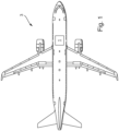
- a water supply and distribution system 1 is generally arranged on-board an aircraft 3 and configured such that it supplies a plurality of consumer assemblies 5 which comprise supply devices 7 such as sinks and toilets in a lavatory or steam ovens and sinks in a galley, with potable water as will be described in detail below.
- Figure 1 only schematically shows the arrangement of the system 1 in the aircraft 3, and several types of arrangements are conceivable.
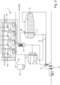
- the water supply and distribution system 1 comprises a central water tank 9 which is provided with a connector 11 at its bottom.
- the connector 11 is connected to a supply line 13 which extends to a fill/drain coupling 15 with a valve 17 being arranged in the supply line 13 adjacent to the fill/drain coupling 15.
- the valve 17 is connected to a control unit 19 of the system 1 and can remotely be controlled such that it can be switched between a closed and an open position.
- the supply line 13 also connects the connector 11 with a central pump 21.
- the central pump 21 is configured as a positive displacement pump and further preferred as a gear pump or a diaphragm pump.
- the central pump 21 is also connected to the control unit 19 and can be operated in a supply mode where it conveys and pressurizes water or other media such as ambient air from its upstream side 23 and the supply line 13 to its downstream side 25 that is connected to a high-pressure conduit system 27 which will be described in detail below.
- the downstream side 25 of the central pump 21 is equipped with a flow sensor 29 and a pressure sensor 31 which are both connected with the control unit 19 and which are capable of monitoring the flow rate of the water conveyed by the central pump 21 and the pressure the water supplied by the pump 21 has.
- the central pump 21 is provided with a backflow prevention mechanism (not shown), which prevents water and/or a gas to flow in an opposite direction from the downstream side 25 to the upstream side 23 when the pump 21 is not operated, or an additional backflow prevention valve (not shown) is provided which is closed, when the central pump 21 is not operated and prevents water and/or a gas to flow from the downstream side 25 to the upstream side 23.
- a backflow prevention mechanism not shown
- an additional backflow prevention valve not shown
- the high-pressure conduit system 27 comprises a plurality of conduits connecting the downstream side 25 of the central pump 21 with the consumer assemblies 5.
- the high-pressure conduit system 27 comprises a pressure reservoir 33 that is configured such that that it applies a pressure at a reservoir pressure level to the high-pressure conduit system 27.
- the reservoir pressure level being the level the pressure has after operation of the central pump 21 has been stopped so that the reservoir pressure level is the level the pressure in the high-pressure conduit system 27 has at that point in time where the central pump 21 was stopped.
- the pressure reservoir 33 can be in the form of a tank containing a gas volume and an elastic membrane that separates the gas volume from a further volume being connected to the high-pressure conduit system and receiving water and/or gas such as ambient air from the conduit system, i.e., the pressure reservoir 33 can be configured in a similar form as in conventional compressors.
- any spring element with reversible spring-back behavior may be employed to bias a membrane or a piston which are part of the reservoir 33.
- Metallic or rubber bellows may also be used.
- an arrangement with a spring-loaded piston that exerts a pressure on a cylinder connected to the high-pressure conduit system 27 is also conceivable.
- the piston in such a arrangement may also be coupled with a linear actuator rather than a spring.
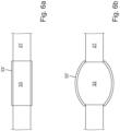
- FIG 6 Aa further embodiment of a pressure reservoir 33 in the high-pressure conduit system 27 is shown figure 6 .
- the component of the high-pressure conduit system having compressibility is an elastic hose element 33'.
- the elastic hose element 33' When the water in them high pressure conduit system 27 is not pressurized, the elastic hose element 33'is not deformed (see figure 1 a)).
- the elastic hose element 33' has spring back behavior so that it deforms when the water in the high-pressure conduit system 27 is pressurized by the central pump 21, as can be seen in figure 1b). In this configuration it applies a pressure on to the water in the system 27 when operation of the pump 21 is stopped, i.e., it acts to maintain the pressure in the system.
- the consumer assembly 5 shown in figure 3 is configured as a lavatory with a sink 35 provided with a faucet 37 and a toilet 39 as supply devices 7.
- a sink 35 provided with a faucet 37 and a toilet 39 as supply devices 7.
- other forms of consumer assemblies are conceivable such as galleys having sinks etc. and that the present invention is not limited to consumer assemblies in the form of lavatories.
- the buffer tanks of galleys may play a more important role in the method of the present invention, as will become clear below.
- the consumer assembly 5 comprises a buffer tank 41 having an inlet 43 and an outlet 45, the inlet 43 being provided with an inlet valve 47 which is connected to a control device 49 which in turn is connected to the control unit 19 so that each of the consumer assemblies 5 can be controlled by and can send signals to the control unit 19 via a data network.
- the position of the inlet valve 47 can be controlled by the control device 49.
- the outlet 45 is connected to the faucet 37 and the toilet 39 via a micro pump 51.
- the line connecting the micro pump 51 with the toilet 39 is also provided with a valve 53 that is controlled by the control device 49.
- the line connecting the micro pump 51 with the faucet 37 is also provided with a valve 55 connected to and controlled by the control device 49.
- combined sensors 56 are provided which sensors 56 are configured such that they monitor both the pressure and the flow rate in the line between the respective valve 53, 55 and the micro pump 51.
- a sole combined sensor 56 is provided on the outlet of micro pump 51 so that the output pressure as well as the flow rate which the water is supplied by the micro pump 51 can be monitored by the control unit 19.
- the buffer tank 41 of each consumer assembly 5 is provided with a level sensor 57 which is connected to the control device 49 and, hence, also to the control unit 19.
- the level sensor 57 is configured such that it provides a signal to the control device 49 indicating the fill level in the buffer tank 41.
- the central tank 9 is provided with a level sensor 59 that is connected to the control unit 19 so that the fill level in the central tank 9 can also electronically be determined by the control unit 19.
- the inlet 43 of the buffer tank 41 of each of the consumer assemblies 5 is connected to the downstream side 25 of the central pump 21 via the high-pressure conduit system 27 and the inlet valve 47, so that the buffer tanks 41 can be supplied with water by the central pump 21.
- control unit 19 of the system 1 in combination with the control device 49 of each of the consumer assemblies 5 are configured such that they operate the system 1 and especially the central pump 21 in this exemplary embodiment in the following manner:
- the central pump 21 is constantly or intermittently operated in a supply mode so that water from the central tank 9 is delivered to the consumer assemblies 5 and their buffer tanks 41, which are connected to the downstream side 25 of the pump 21 via the high pressure conduit system 27, so that the buffer tanks 41 of the consumer assemblies 5 are filled.
- the inlet valves 47 of those consumer assemblies 5 the buffer tanks 41 of which shall be filled are at the same time or a subsequently brought into its open position.
- the level in the buffer tanks 41 may be monitored by means of the level sensors 57. Further, the water may be supplied from the buffer tank 41 to the faucet 37 or the toilet 39 by operating the micro pump 51 and opening the respective valves 53, 55.
- control unit 19 and the control devices 49 of the consumer assemblies 5 when starting the aircraft or during operation, with the control unit 19 and the control devices 49 being configured correspondingly:
- This procedure allows to determine whether the central tank 9 and the supply line 13 to the central pump 21 comprise any leakages. In case the level in the central tank 21 decreases by more than the predetermined amount, the corresponding failure signal is generated and supplied to the aircraft data network ADN.
- means other than the central pump 29 may by employed as the source for pressurized gas.
- a ground pressure source may be used or the high-pressure conduit system 27 may be configured such that it comprises an interface which can connected to an interface of the cabin pressurization system or, as an alternative, it may also be connected to an interface of the bleed air system.
- this procedure allows to determine whether in at least one of the consumers assemblies 5 a leak is present. Further, this procedure generally allows, in combination with Procedure 1 or 3, to determine in which path to the consumer assemblies 5 a leak is present when a failure signal was generated by Procedure 1 or 3.For this purpose, the procedure has to be carried out with the buffer tank 41 of each of the consumer assemblies 5 subsequently being filled until a failure signal is generated (see Procedure 6). Moreover, if Procedures 1 or 2 do not identify a leak, but the time required for achieving a certain difference in the filling level in this procedure is above the predefined limit, a partial or total blockage can also be present (upstream or downstream the pump).
- This procedure allows to check whether there is any leakage in the monument comprising that consumer assembly 5 the level in the buffer tank 41 is monitored.
- the flow of water from the upstream side 23 to the downstream side 25 and into the high-pressure conduit system 27 can be monitored by the control unit 19 and the flow sensor 29 so that the predetermined period of time is calculated by the control unit 19 based on the monitored flow of water from the upstream side 23 to the downstream side 25 and into the high-pressure conduit system 27.
- this procedure allows to check whether any blockages are in the path between the central pump 21 to the buffer tank 41 each of the consumer assemblies 5, because the respective test is conducted for each of the consumer assemblies 5 separately. However, for confirming that a leak or blockage is present in that region it is additionally required that a certain minimum pressure of the pump 21 is reached. Otherwise, the pump 21 could also be damaged or it could have a leak.
- this procedure when combined with Procedure 6, also allows to check whether any blockages are present in the path between the central tank 9 and the central pump 21 and whether the pump is operating in the right manner. Further it is to be noted, that the flow of water through the central pump 21 can be measured by means of the flow sensor 29 or inverse methods may also be used such as detecting the rotational speed of the central pump 21 to derive the flow if the pressure is measured by means of the pressure sensor 31 downstream the central pump 21.
- This procedure also allows to determine whether in the path between the central pump 21 and the supply device of the one consumer assembly 5 leaks are present.
- the supply device i.e., the faucet 37 or the toilet 39
- the connection between the buffer tank 41 and the supply device 7 is checked whether there is any kind of blockage.
- the drop of the filling level in the respective buffer tank 41 would remain below a predetermined value. If this is detected a further failure signal is generated and transmitted via the aircraft data network ADN. On the other hand, if the pressure drop is above the predetermined value, a test-passed signal may again be generated.
- Procedure 9 it is possible to check whether the supply devices 7 of the consumer assemblies 5 are operating properly.
- the consumer assembly 5 in question is tested by means of pressurizing the water in the conduits whether there is a leak.
- ADN aircraft data network
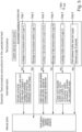
- a preferred embodiment for a test procedure during start-up of an aircraft or for a general system test is initiated in step 1.
- Procedure 1 is conducted, and in case a failure signal is generated, the test procedure stops and it will be required that the on-board supply system is sent to a maintenance procedure.
- step 3 is conducted, i.e., above Procedure 2 is performed.
- the central tank 9 is automatically drained and it is again required that a maintenance procedure is conducted.
- step 3 If in step 3 no leakage is found, the test procedure proceeds to step 4 where Procedure 7 is performed.
- Procedure 7 is repeated so as to rule out that the blockage is due to freezing in the low-pressure section. Additionally, the ambient temperature may be monitored, so as to determine whether freezing is the reason for the problem. In case the problem continues to be present, the test procedure stops, and a maintenance procedure will again be required.
- step 4 When in step 4 no blockage or pump malfunctioning is found, the test procedure proceeds to step 5 where above Procedures 3, 4 and 8 are performed. If in this step again a leakage in the high pressure conduit system 27 is detected, the central pump 21 is automatically switched off, the test procedure stops and a maintenance procedure will be initiated.
- step 5 no leakage is detected, the test procedure proceeds to step 6, and above Procedure 6 is performed. If in this step a blockage is detected, Procedure 6 is repeated to again rule out that freezing is the reason. In case the problem continues to be present, the test procedure stops by initiating a maintenance procedure.
- step 6 When in step 6 no blockage is detected, the test procedure proceeds to step 7 where above Procedures 5 and 10a to 10d are conducted. In case a failure signal is generated that monument where the leakage or blockage was detected is disabled by closing the respective inlet valve 47, and the buffer tank 41 is emptied manually.
- step 7 no leakage is detected, the test procedure proceeds to step 8, and Procedure 9 is carried out to check whether there are any blockages in the connections between the buffer tanks 41 and the supply devices. If this does not reveal any issues, the test procedure proceeds to the end and normal operation of the aircraft can be initiated.
- test procedures More preferable only a subset of the defined possible test procedures will be conducted during aircraft start-up in order to be fast and efficient. At the same time, certain tests can also be carried out after a predefined time period has elapsed. For example every 10 days or every 20 flight cycles. Furthermore, it is also conceivable that different combinations of procedures are conducted in order to further localize a leak or blockage, when a failure was detected in one of the afore-mentioned steps.
- the preferred embodiment of a test procedure during operation of an aircraft 3, i.e., when the aircraft is in flight, includes the following steps 1 to 5 which can be performed in an arbitrary order and depending on the actual use of the onboard supply system 1.
- the respective tests can be carried out continuously in an arbitrary order and based on the operating parameters which are available on the aircraft data network ADN. Operational interruptions of the system are not required.
- step 1 above Procedure 2 is conducted. This can be done whenever the pump 21 is not in use. In case in this procedure a leakage in the low-pressure section upstream the central pump 21 is detected, the central tank 9 is automatically drained so as to prevent water ingress in the fuselage of the aircraft 3.
- Step 2 can be carried out during normal use whenever the pump is not operating.
- above procedure 7 is conducted.
- those consumer assemblies 5 such as lavatories are disabled which are affected by the blockage.
- Procedures 3, 4 and 8 are carried out, which requires at that time that it is not needed to transfer water via the high-pressure conduit system.
- the pump 21 is switched off if necessary, the inlet valve 47 of the consumer assembly 5 where a leak is detected is closed and/or the sign "lav occupied" may be activated.
- Procedure 6 is executed. If it turns out that a blockage is present, the respective sections and consumer assemblies 5 are again disabled.
- step 5 Procedures 5 and 10a to 10d are carried out. In case this procedure detects leakages or blockages, the respective inlet valves 47 of the consumer assemblies 5 are closed and the buffer tanks 41 of these assemblies are automatically drained.
- step 6 it is checked whether the path between the buffer tanks 41 and the respective supply devices 7 (Procedure 9) are working properly.
- a system test can also be initiated by the cabin crew via the flight attendant panel or by the flight crew via the aircraft maintenance system in case they assume a leak or a malfunction of the water system for example an abnormal low water tank capacity or low water pressure at the point of use.
- the present invention provides for an efficient method to check the status of an on-board water supply and distribution system without the need to visually inspect such system.
Landscapes
- Engineering & Computer Science (AREA)
- Health & Medical Sciences (AREA)
- Life Sciences & Earth Sciences (AREA)
- Hydrology & Water Resources (AREA)
- Public Health (AREA)
- Water Supply & Treatment (AREA)
- Physics & Mathematics (AREA)
- Aviation & Aerospace Engineering (AREA)
- Fluid Mechanics (AREA)
- General Physics & Mathematics (AREA)
- Structural Engineering (AREA)
- Mechanical Engineering (AREA)
- Automation & Control Theory (AREA)
- Manufacturing & Machinery (AREA)
- Transportation (AREA)
- Pipeline Systems (AREA)
Priority Applications (3)
| Application Number | Priority Date | Filing Date | Title |
|---|---|---|---|
| EP22215097.1A EP4389601A1 (de) | 2022-12-20 | 2022-12-20 | Wasserversorgungs- und -verteilungssystem an bord eines flugzeugs und verfahren zum betrieb solch eines systems |
| CN202311757069.4A CN118223566A (zh) | 2022-12-20 | 2023-12-19 | 飞行器的机载式水供应与分配系统及操作这种系统的方法 |
| US18/544,906 US12509865B2 (en) | 2022-12-20 | 2023-12-19 | Water supply and distribution system on-board an aircraft and method for operating such system |
Applications Claiming Priority (1)
| Application Number | Priority Date | Filing Date | Title |
|---|---|---|---|
| EP22215097.1A EP4389601A1 (de) | 2022-12-20 | 2022-12-20 | Wasserversorgungs- und -verteilungssystem an bord eines flugzeugs und verfahren zum betrieb solch eines systems |
Publications (1)
| Publication Number | Publication Date |
|---|---|
| EP4389601A1 true EP4389601A1 (de) | 2024-06-26 |
Family
ID=84888618
Family Applications (1)
| Application Number | Title | Priority Date | Filing Date |
|---|---|---|---|
| EP22215097.1A Pending EP4389601A1 (de) | 2022-12-20 | 2022-12-20 | Wasserversorgungs- und -verteilungssystem an bord eines flugzeugs und verfahren zum betrieb solch eines systems |
Country Status (3)
| Country | Link |
|---|---|
| US (1) | US12509865B2 (de) |
| EP (1) | EP4389601A1 (de) |
| CN (1) | CN118223566A (de) |
Citations (4)
| Publication number | Priority date | Publication date | Assignee | Title |
|---|---|---|---|---|
| US20060260691A1 (en) * | 2005-05-20 | 2006-11-23 | Davidoff John A | Systems and methods for detecting and preventing fluid leaks |
| US20180291595A1 (en) * | 2017-04-07 | 2018-10-11 | Airbus Operations Gmbh | Aircraft comprising a high-pressure water supply and distribution system |
| EP3738880A1 (de) * | 2019-04-12 | 2020-11-18 | Goodrich Corporation | Leckerkennung für flugzeuge |
| EP4080297A1 (de) * | 2021-04-23 | 2022-10-26 | Airbus Operations GmbH | Wasserversorgungssystem für ein flugzeug |
Family Cites Families (7)
| Publication number | Priority date | Publication date | Assignee | Title |
|---|---|---|---|---|
| US5303739A (en) * | 1991-09-30 | 1994-04-19 | Deutsche Aerospace Airbus Gmbh | Fresh water supply system for an aircraft |
| DE4202719C2 (de) * | 1992-01-31 | 1993-11-04 | Deutsche Aerospace Airbus | Wassersystem fuer ein flugzeug |
| US20120111432A1 (en) * | 2010-11-10 | 2012-05-10 | Goodrich Corporation | Aircraft potable water system |
| DE102011109943A1 (de) | 2011-08-10 | 2013-02-14 | Airbus Operations Gmbh | Druckversorgung für ein Wassersystem |
| US10590634B2 (en) * | 2016-03-16 | 2020-03-17 | Goodrich Corporation | Pressurized potable water system with conformal shape water storage tank |
| DK3385361T3 (da) | 2017-04-05 | 2019-06-03 | Ab Enzymes Gmbh | Detergentsammensætninger omfattende bakterielle mannanaser |
| JP7202872B2 (ja) * | 2018-12-17 | 2023-01-12 | 日機装株式会社 | 航空機用水供給システム |
-
2022
- 2022-12-20 EP EP22215097.1A patent/EP4389601A1/de active Pending
-
2023
- 2023-12-19 CN CN202311757069.4A patent/CN118223566A/zh active Pending
- 2023-12-19 US US18/544,906 patent/US12509865B2/en active Active
Patent Citations (4)
| Publication number | Priority date | Publication date | Assignee | Title |
|---|---|---|---|---|
| US20060260691A1 (en) * | 2005-05-20 | 2006-11-23 | Davidoff John A | Systems and methods for detecting and preventing fluid leaks |
| US20180291595A1 (en) * | 2017-04-07 | 2018-10-11 | Airbus Operations Gmbh | Aircraft comprising a high-pressure water supply and distribution system |
| EP3738880A1 (de) * | 2019-04-12 | 2020-11-18 | Goodrich Corporation | Leckerkennung für flugzeuge |
| EP4080297A1 (de) * | 2021-04-23 | 2022-10-26 | Airbus Operations GmbH | Wasserversorgungssystem für ein flugzeug |
Also Published As
| Publication number | Publication date |
|---|---|
| US20240200311A1 (en) | 2024-06-20 |
| CN118223566A (zh) | 2024-06-21 |
| US12509865B2 (en) | 2025-12-30 |
Similar Documents
| Publication | Publication Date | Title |
|---|---|---|
| US10422117B2 (en) | Sanitary unit with monitoring device | |
| US11175683B2 (en) | High integrity protection system for hydrocarbon flow lines | |
| US20110030839A1 (en) | Apparatus and method for fuelling an aircraft tank system | |
| US12497765B2 (en) | Water supply and distribution system on-board an aircraft and method for operating such system | |
| WO2019190808A1 (en) | High integrity protection system for hydrocarbon flow lines | |
| CN102016331A (zh) | 尤其用于航空器的蓄能器状态的控制方法 | |
| CN113048407A (zh) | 用于检测和疏通飞机废水管路堵点的系统及其控制方法 | |
| EP4389601A1 (de) | Wasserversorgungs- und -verteilungssystem an bord eines flugzeugs und verfahren zum betrieb solch eines systems | |
| US8502700B2 (en) | Apparatus and method for pressurising an aircraft cabin structure and measuring the amount of leakage of the aircraft cabin structure | |
| KR200445590Y1 (ko) | 주유소의 이상 발생 모니터링 장치 | |
| US12534387B2 (en) | Water supply and distribution system on-board an aircraft and method for operating such system with low maintenance effort | |
| JPH02247534A (ja) | 導管系の漏れモニター方法及び装置 | |
| US12203247B2 (en) | Water supply and distribution system on-board an aircraft and method for self-sustaining hygienic operation of such system | |
| JP5295886B2 (ja) | 予作動式スプリンクラ消火設備 | |
| US20230382532A1 (en) | Method for draining a local water distribution system | |
| AU2011258681B2 (en) | Methods and apparatus for removing fluid from valves | |
| CN109752311A (zh) | 腐蚀挂片在线监测结构及其在线监测方法 | |
| EP4361040A1 (de) | Wasserversorgungssystem mit querverbindung und flugzeug mit einem wasserversorgungssystem | |
| RU2649518C1 (ru) | Способ содействия обнаружению повреждения трубопровода турбореактивного двигателя | |
| RU2287458C1 (ru) | Топливная система самолета | |
| JP3170087B2 (ja) | 給水装置 | |
| JP2004125735A (ja) | ガス配管の漏洩検査方法及びそれに用いる漏洩検査装置 | |
| CN100585370C (zh) | 测试飞机油箱系统的设备和方法 | |
| CN116263369A (zh) | 一种大型油气田站场消防泵泄压回流检测系统及检测方法 | |
| CN101081689B (zh) | 给飞机油箱系统加燃料的设备和方法 |
Legal Events
| Date | Code | Title | Description |
|---|---|---|---|
| PUAI | Public reference made under article 153(3) epc to a published international application that has entered the european phase |
Free format text: ORIGINAL CODE: 0009012 |
|
| STAA | Information on the status of an ep patent application or granted ep patent |
Free format text: STATUS: THE APPLICATION HAS BEEN PUBLISHED |
|
| AK | Designated contracting states |
Kind code of ref document: A1 Designated state(s): AL AT BE BG CH CY CZ DE DK EE ES FI FR GB GR HR HU IE IS IT LI LT LU LV MC ME MK MT NL NO PL PT RO RS SE SI SK SM TR |
|
| STAA | Information on the status of an ep patent application or granted ep patent |
Free format text: STATUS: REQUEST FOR EXAMINATION WAS MADE |
|
| 17P | Request for examination filed |
Effective date: 20241220 |
|
| STAA | Information on the status of an ep patent application or granted ep patent |
Free format text: STATUS: EXAMINATION IS IN PROGRESS |
|
| 17Q | First examination report despatched |
Effective date: 20251024 |