EP4389624A1 - Récipient en matière plastique avec section de déformation - Google Patents
Récipient en matière plastique avec section de déformation Download PDFInfo
- Publication number
- EP4389624A1 EP4389624A1 EP23213939.4A EP23213939A EP4389624A1 EP 4389624 A1 EP4389624 A1 EP 4389624A1 EP 23213939 A EP23213939 A EP 23213939A EP 4389624 A1 EP4389624 A1 EP 4389624A1
- Authority
- EP
- European Patent Office
- Prior art keywords
- section
- plastic container
- container
- longitudinal direction
- rib
- Prior art date
- Legal status (The legal status is an assumption and is not a legal conclusion. Google has not performed a legal analysis and makes no representation as to the accuracy of the status listed.)
- Pending
Links
Images




Classifications
-
- B—PERFORMING OPERATIONS; TRANSPORTING
- B65—CONVEYING; PACKING; STORING; HANDLING THIN OR FILAMENTARY MATERIAL
- B65D—CONTAINERS FOR STORAGE OR TRANSPORT OF ARTICLES OR MATERIALS, e.g. BAGS, BARRELS, BOTTLES, BOXES, CANS, CARTONS, CRATES, DRUMS, JARS, TANKS, HOPPERS, FORWARDING CONTAINERS; ACCESSORIES, CLOSURES, OR FITTINGS THEREFOR; PACKAGING ELEMENTS; PACKAGES
- B65D1/00—Rigid or semi-rigid containers having bodies formed in one piece, e.g. by casting metallic material, by moulding plastics, by blowing vitreous material, by throwing ceramic material, by moulding pulped fibrous material or by deep-drawing operations performed on sheet material
- B65D1/02—Bottles or similar containers with necks or like restricted apertures, designed for pouring contents
- B65D1/0223—Bottles or similar containers with necks or like restricted apertures, designed for pouring contents characterised by shape
-
- B—PERFORMING OPERATIONS; TRANSPORTING
- B65—CONVEYING; PACKING; STORING; HANDLING THIN OR FILAMENTARY MATERIAL
- B65D—CONTAINERS FOR STORAGE OR TRANSPORT OF ARTICLES OR MATERIALS, e.g. BAGS, BARRELS, BOTTLES, BOXES, CANS, CARTONS, CRATES, DRUMS, JARS, TANKS, HOPPERS, FORWARDING CONTAINERS; ACCESSORIES, CLOSURES, OR FITTINGS THEREFOR; PACKAGING ELEMENTS; PACKAGES
- B65D79/00—Kinds or details of packages, not otherwise provided for
- B65D79/005—Packages having deformable parts for indicating or neutralizing internal pressure-variations by other means than venting
- B65D79/008—Packages having deformable parts for indicating or neutralizing internal pressure-variations by other means than venting the deformable part being located in a rigid or semi-rigid container, e.g. in bottles or jars
- B65D79/0084—Packages having deformable parts for indicating or neutralizing internal pressure-variations by other means than venting the deformable part being located in a rigid or semi-rigid container, e.g. in bottles or jars in the sidewall or shoulder part thereof
-
- B—PERFORMING OPERATIONS; TRANSPORTING
- B65—CONVEYING; PACKING; STORING; HANDLING THIN OR FILAMENTARY MATERIAL
- B65D—CONTAINERS FOR STORAGE OR TRANSPORT OF ARTICLES OR MATERIALS, e.g. BAGS, BARRELS, BOTTLES, BOXES, CANS, CARTONS, CRATES, DRUMS, JARS, TANKS, HOPPERS, FORWARDING CONTAINERS; ACCESSORIES, CLOSURES, OR FITTINGS THEREFOR; PACKAGING ELEMENTS; PACKAGES
- B65D21/00—Nestable, stackable or joinable containers; Containers of variable capacity
- B65D21/02—Containers specially shaped, or provided with fittings or attachments, to facilitate nesting, stacking, or joining together
- B65D21/0209—Containers specially shaped, or provided with fittings or attachments, to facilitate nesting, stacking, or joining together stackable or joined together one-upon-the-other in the upright or upside-down position
-
- B—PERFORMING OPERATIONS; TRANSPORTING
- B65—CONVEYING; PACKING; STORING; HANDLING THIN OR FILAMENTARY MATERIAL
- B65D—CONTAINERS FOR STORAGE OR TRANSPORT OF ARTICLES OR MATERIALS, e.g. BAGS, BARRELS, BOTTLES, BOXES, CANS, CARTONS, CRATES, DRUMS, JARS, TANKS, HOPPERS, FORWARDING CONTAINERS; ACCESSORIES, CLOSURES, OR FITTINGS THEREFOR; PACKAGING ELEMENTS; PACKAGES
- B65D2501/00—Containers having bodies formed in one piece
- B65D2501/0009—Bottles or similar containers with necks or like restricted apertures designed for pouring contents
- B65D2501/0018—Ribs
- B65D2501/0036—Hollow circonferential ribs
Definitions
- the present invention relates to a plastic container for holding liquids and in particular drinks.
- plastic containers have been known for a long time and are now the predominant drinks packaging in the drinks industry. After production and filling, these containers are usually stacked on pallets. In order to ensure pallet stability for storage and transport and an intact bottle, the containers need a certain "filled top load" as a resistance to the vertical forces that occur during stacking. In the case of lighter drinks containers, this resistance builds up through the vertical compression of the container and the parallel increase in the internal pressure of the container. The areas in which the container can be compressed are usually the base of the container and any places in the middle of the container that have a smaller diameter (pinch).
- the internal pressure in the vertical direction contributes less to the force that the container can exert.
- a deformation takes place, which builds up the top load.
- the shoulder of the container should not generally collapse, as deformations there do not compensate for the opposite when the load is removed.
- the container is deformed in this way, in particular by a mouthpiece snapping into the shoulder.
- the present invention is therefore based on the object of providing a plastic container which can withstand a certain top load or loads in its longitudinal direction. In particular, this should not lead to permanent deformation of the container.
- a plastic container according to the invention for holding liquids and in particular drinks has a base section, a base body which adjoins the base section and forms a receiving volume for holding the liquid and which extends in a longitudinal direction of the plastic container.
- a shoulder region is provided in which a cross-section in the longitudinal direction decreases and a mouth region adjoining the shoulder region in the longitudinal direction, in which a mouth is formed through which the liquid can be fed to the container.
- the shoulder region and the mouth region are arranged in an upper section of the plastic container in relation to the longitudinal direction.
- the plastic container has a deformation section in the upper section and in the longitudinal direction below the mouth section and in particular also below the shoulder section, in which the plastic container is deformable and in particular elastically deformable with respect to its longitudinal direction.
- the container is compressible in its longitudinal direction, in particular by the said deformation region.
- the container is a disposable plastic container.
- the container is intended for holding non-carbonated beverages.
- this compressible deformation region is of an approximately constant diameter.
- this compressible deformation area is not of a constant diameter, but rather conical.
- the ribbing present in this section ensures that the section can be stably compressed and does not fold inwards. This is achieved by a corresponding rib geometry, which causes the ribs to support one another when the spring is compressed in this section.
- the rib geometry causes a defined deformation pattern.
- the deformation region has a plurality of grooves.
- at least two of these grooves have a different or varying groove depth. It is thus possible for two groups of grooves with different groove depths to be provided, but several, for example at least three or at least four grooves with a different groove depth can also be provided.
- these grooves are formed at least partially circumferentially around the longitudinal direction of the container.
- the container is circular or rotationally symmetrical to its longitudinal direction.
- the base section has a plurality of first ribs which extend outward from a center of the base section and in particular extend radially outward.
- a plurality of second ribs are provided which extend radially but are preferably shorter than the first mentioned ribs.
- the first ribs and the second ribs are arranged alternately in the circumferential direction of the base portion.
- the short ribs extend radially inwards and end - preferably tapered - in front of the central region mentioned.
- an injection point of the container i.e. an injection point of the plastic preform from which the container was produced
- said central region and/or the base section has a dome-like structure.
- the mouth has a thread and in particular an external thread.
- this is a screw thread onto which a container closure can be screwed.
- This container closure can be a conventional container closure.
- other types of closures such as threadless closures, could also be used.
- An example of this are so-called snap-on closures, which do not have a thread but are pressed onto the container.
- a height of the deformation section in the longitudinal direction is less than a height of the base body in the longitudinal direction and/or less than a height in the longitudinal direction of the shoulder region.
- the deformation section (relative to the longitudinal direction and relative to an upright state of the container) is arranged in the upper half of the container, preferably in an upper third of the plastic container.
- the upper half is understood with reference to an upright state of the container.
- the plastic container is preferably a blow-molded plastic container and in particular a stretch blow-molded plastic container.
- the deformation section is arranged in the longitudinal direction of the plastic container directly below the shoulder region. In a further advantageous embodiment, the deformation section is arranged in the longitudinal direction directly above the base body. The deformation section preferably directly connects the base body to the shoulder region.
- a conical section is provided between the deformation area and the base body.
- This conical section preferably tapers in the direction of the mouth of the container.
- a diameter of the container is reduced by at least 5%, preferably by at least 10%.
- a diameter of the container is reduced by at most 50%, preferably by at most 40% and particularly preferably by at most 30%.
- This section is particularly preferably used to prevent the container from "turtling" and/or falling over.
- the deformation section has a smaller cross-section than the base body and particularly preferably a cross-sectional area of the deformation section is between 60% and 98% of the cross-sectional area of the base body, preferably between 70% and 95% of the cross-sectional area of the base body, preferably between 80% and 95% of the cross-sectional area of the base body.
- the cross-sectional area of the deformation section tapers upwards in the longitudinal direction of the container.
- a minimum cross-section of the deformation section has a ratio to a maximum cross-section of the deformation section which is between 0.35 and 0.80, preferably between 0.45 and 0.70 and particularly preferably between 0.55 and 0.60.
- the base body has a labeling area in which the cross section of the container is or remains substantially constant in the longitudinal direction.
- This labeling area is preferably formed within the base body in the longitudinal direction, i.e. the labeling area connects a first section of the base body to a second section of the base body.
- the base body has a smaller cross-section in the labeling area than in the areas below and above.
- a grooved section with a plurality of grooves extending one above the other and preferably perpendicular to the longitudinal direction is provided in the longitudinal direction of the container above the labeling area.
- these grooves have the same cross-section. These grooves preferably contribute to the stability of the container in the radial direction of the container.
- At least partially continuous grooves are provided. These provide improved grip stability and keep the diameter more stable. It is possible that some grooves are designed somewhat deeper in order to provide increased grip stability.
- the plastic container has at least one first rib in the deformation section that runs around at least part of the container.
- This rib or groove is preferably directed in the direction of the inner volume of the container.
- This rib particularly preferably has sections with different radii of curvature and/or different cross sections.
- this groove In a plane which contains the longitudinal direction of the container and a direction extending from the longitudinal direction to the groove, this groove, when viewed from above, preferably has an outwardly curved region with a radius of curvature of between 1 mm and 2 mm. This region is preferably followed by a further inwardly curved radius, which is preferably between 0.1 mm and 0.3 mm.
- This groove particularly preferably also has a straight section, which particularly preferably widens outwards, from top to bottom.
- the first rib has several rib sections which adjoin one another in the circumferential direction of the deformation section. These rib sections preferably adjoin one another directly. These rib sections are particularly preferably arranged at the same height in relation to the longitudinal direction of the container.
- the number of these rib sections is greater than two, preferably greater than 3 and preferably greater than 4. In a further advantageous embodiment, the number of rib sections is less than 13, preferably less than 12, preferably less than 10 and preferably less than 7.
- the plastic container has a second rib which runs around at least some of the deformation section, the second rib being offset from the first rib in the longitudinal direction.
- the second rib particularly preferably adjoins the first rib directly in the longitudinal direction.
- the second rib is designed in a similar manner to the first rib and in particular has a similar cross-section.
- the second rib also has a plurality of rib sections which adjoin one another in the circumferential direction of the deformation section, wherein the rib sections of the second rib are advantageously offset and/or rotated in the circumferential direction relative to the rib sections of the first rib.
- the second ribs are offset by half a pitch relative to the first ribs.
- the number of second rib sections corresponds to the number of first rib sections.
- the first rib sections and/or the second rib sections enclose an angle in the circumferential direction of the container that is greater than 25°, preferably greater than 40°, preferably greater than 50° and preferably greater than 60°.
- the first rib sections and/or the second rib sections enclose an angle in the circumferential direction of the container that is less than 200°, preferably less than 180°, preferably less than 140°, preferably less than 130°, particularly preferably less than 100°.
- the plastic container has a third rib in the deformation area, which is preferably arranged in the longitudinal direction of the container above the first and second ribs. Particularly preferably, this also has third rib has a plurality of rib sections. Particularly preferably, the rib sections of the third rib are rotated or offset in the circumferential direction relative to the rib sections of the second rib. Particularly preferably, the rib sections of the third rib are arranged in the same rotational positions relative to the rib sections of the first rib.
- a further rib and/or groove extending in the circumferential direction is formed in the shoulder section.
- This rib is particularly preferably formed with a uniform cross-section and particularly preferably completely circumferential.
- This further rib particularly preferably serves to relieve the load on the plastic container.
- This further rib particularly preferably has a smaller cross-section than the ribs in the deformation region.
- the geometric design of the container described here means that the deformation required to build up the necessary top load is placed in the upper area of the container and is also made reversible. In this way, the design is not destroyed by the top load. This has advantages both when stacking the container and for the integrity of the design. This means that mechanically stable and easily stackable bottles can be produced even with very low container weights.
- the plastic container has a capacity that is greater than 100 ml, preferably greater than 300 ml and preferably greater than 400 ml. In a further preferred embodiment, the plastic container has a capacity that is a maximum of 8 l, preferably a maximum of 2.0 l, preferably a maximum of 1.5 l.
- the present invention is further directed to a molding tool and in particular a blow mold for producing a plastic container of the type described above.
- This blow mold is particularly preferably formed in at least two parts, particularly preferably at least three parts.
- the blow mold particularly preferably has at least two side parts which have a corresponding negative to the plastic container to be produced or whose inner wall is formed accordingly.
- the present invention is further directed to a method for producing a container of the type described above.
- the method is a blow molding method and in particular a stretch blow molding method.
- the container described above is produced by means of a rotary machine.
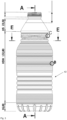
- Fig.1 shows a view of a plastic container 1 according to the invention.
- This has a base section 2.
- This base section 2 is followed by a base body 4 of the container, which forms a significant part of the receiving volume for a liquid.
- a labeling area 42 is provided within this base body.
- the reference symbol hG indicates the height of this base body in the longitudinal direction of the container.
- the reference symbol hB indicates the height of the base section (also in relation to the longitudinal direction).
- the base body is adjoined in the longitudinal direction L of the container by the lower shoulder, then by the above-mentioned deformation section 6, which has a height hD.
- This deformation section 6 is adjoined by the shoulder region 8 of the container and this in turn is adjoined by a mouth region 10 with a height hM.
- the base body section extends over more than half the height of the entire container.
- the height hD of the deformation section is preferably less than the height hS of the shoulder area and also less than the height hG of the base body.
- the reference numeral 12 refers to a conical region which is preferably arranged between the deformation section and the base body 4 and which particularly preferably tapers towards the top.
- Fig. 2a shows a detailed view of the Fig.1 shown container.
- the groove 62 has three groove sections 62a, 62b and 62c, which adjoin one another and lie one behind the other in the circumferential direction. A groove base of these three groove sections is always the same size.
- the cross section of a groove section such as the groove section 62b preferably widens from its starting point A into a middle region M and then tapers again to its end section B.
- the groove sections are preferably each symmetrical with respect to a Plane which extends in the longitudinal direction of the container through the center of the groove sections and which runs in a radial direction of the plastic container.
- groove sections 64a and 64b are offset by half a pitch in the circumferential direction of the container compared to the groove sections 62a, 62b and 62c.
- a further groove 82 is provided, which is formed in the shoulder region 8. It can be seen that this further groove is formed circumferentially without interruption.
- Fig. 2b shows a further detailed representation of a slightly modified container, which can, however, preferably be combined with the above embodiments.
- the groove 62 has three groove sections 62a, 62b and 62c which adjoin one another and lie one behind the other in the circumferential direction. A groove base of these three groove sections is always the same size.
- the cross section of a groove section such as the groove section 62b preferably widens from its starting point A into a central region M and then tapers again to its end section B.
- the groove sections are preferably each symmetrical with respect to a plane which extends in the longitudinal direction of the container through the middle of the groove sections and which runs in a radial direction of the plastic container.
- groove sections 64a and 64b are offset by half a pitch in the circumferential direction of the container compared to the groove sections 62a, 62b and 62c.
- the groove 66 also has three groove sections 66a, 66b and 66c. In the rotational position, these are again arranged in the same position as the groove sections 62a, 62b and 62c of the groove 62.
- a further groove 82 is provided, which is formed in the shoulder area 8. It can be seen that this further groove is uninterrupted is formed all around.
- Fig.3 shows a representation of the Fig.2 shown container, in which individual sections A, B, C and E are highlighted in order to illustrate them in more detail below. It can be seen that here too a large number of grooves are formed above the labeling area 42 and below it.
- Fig.4 shows a detailed view of the base body and the grooves arranged there. It can be seen here that these grooves are connected to one another by a very short groove base.
- the grooves have a radius of curvature that is between 1 mm and 2 mm, preferably between 1.2 mm and 1.8 mm and particularly preferably between 1.3 mm and 1.7 mm.
- Fig.5 shows a detailed view of an area of the uppermost groove 66 in the deformation section. It can be seen that, viewed from above, the wall has a radius of curvature R1 and below it transitions into an approximately straight section via an inwardly curved radius of curvature R2.
- Fig.6 shows a top view of the Fig.1 shown container. It can be seen that this container is essentially rotationally symmetrical with respect to its longitudinal direction L. In addition, the grooves 62, 64 and 66 in the deformation section can also be seen from above.
- Fig.7 shows a view from below of the bottom section of the container. Here you can see a total of eight long ribs 32 running in the radial direction, which end in the central area 34 of the bottom section.
- the reference number 36 designates a center of the bottom section which preferably has the injection point.
- the reference numerals 38 identify further - albeit shortened - radial ribs, which are each arranged between the first reinforcing ribs 32. These second radial ribs 38 also extend in the radial direction R but not as far as the central region, but rather they end approximately halfway down the base section.
- Fig.8 shows a view along the arrows EE from Fig.3 , ie in the area of the first rib 62 of the deformation section. It can be seen that there are a total of four rib sections 62A, 62B, 62C and 62D are provided. The cross-section is maximum at the respective connection points between the rib sections 62.
- Fig.9 shows a sectional view of the container according to the invention. Numerous diameters D1 - D14 are shown here. For example, the diameter D3 can be seen here, which is also the diameter of the base of the container. In the area of the labeling section, a maximum cross section D4 and a minimum section D5 are shown. However, these preferably differ by less than 10%, preferably by less than 5%.
- the diameters D8 - D12 mark the individual ribs 62, 64 in the deformation section 6. It can be seen that overall the rib 64 has a smaller diameter than the rib 62.
- the base section extends slightly inwards, which is indicated by the distance A1.
- the reference symbol hE indicates the height of the labeled section 42.
Landscapes
- Engineering & Computer Science (AREA)
- Mechanical Engineering (AREA)
- Ceramic Engineering (AREA)
- Containers Having Bodies Formed In One Piece (AREA)
Applications Claiming Priority (1)
| Application Number | Priority Date | Filing Date | Title |
|---|---|---|---|
| DE102022134017.1A DE102022134017A1 (de) | 2022-12-20 | 2022-12-20 | Kunststoffbehältnis mit Deformationsabschnitt |
Publications (1)
| Publication Number | Publication Date |
|---|---|
| EP4389624A1 true EP4389624A1 (fr) | 2024-06-26 |
Family
ID=89076248
Family Applications (1)
| Application Number | Title | Priority Date | Filing Date |
|---|---|---|---|
| EP23213939.4A Pending EP4389624A1 (fr) | 2022-12-20 | 2023-12-04 | Récipient en matière plastique avec section de déformation |
Country Status (4)
| Country | Link |
|---|---|
| US (1) | US20240199299A1 (fr) |
| EP (1) | EP4389624A1 (fr) |
| CN (1) | CN222452830U (fr) |
| DE (1) | DE102022134017A1 (fr) |
Cited By (1)
| Publication number | Priority date | Publication date | Assignee | Title |
|---|---|---|---|---|
| WO2026057623A1 (fr) * | 2024-09-11 | 2026-03-19 | Krones Ag | Récipient en plastique sans étiquette avec partie de déformation, outil et procédé de fabrication d'un tel récipient |
Families Citing this family (1)
| Publication number | Priority date | Publication date | Assignee | Title |
|---|---|---|---|---|
| DE102024128005A1 (de) * | 2024-09-27 | 2026-04-02 | Khs Gmbh | Getränkebehälter für nicht-karbonisierte Getränke |
Citations (4)
| Publication number | Priority date | Publication date | Assignee | Title |
|---|---|---|---|---|
| US8104632B2 (en) * | 2006-06-30 | 2012-01-31 | Yoshino Kogyosho Co., Ltd. | Synthetic resin bottle having a constricted portion with intermittent lateral grooves |
| WO2015076362A1 (fr) * | 2013-11-22 | 2015-05-28 | ザ コカ・コーラ カンパニー | Bouteille en matière plastique |
| WO2019172080A1 (fr) * | 2018-03-05 | 2019-09-12 | サントリーホールディングス株式会社 | Bouteille en plastique |
| US20210031965A1 (en) * | 2012-12-27 | 2021-02-04 | Niagara Bottling, Llc | Plastic Container With Strapped Base |
Family Cites Families (3)
| Publication number | Priority date | Publication date | Assignee | Title |
|---|---|---|---|---|
| FR2259754A2 (en) * | 1974-02-05 | 1975-08-29 | Ricard Marcel | Collapsible plastic bottle with bellows wall - has diamond shaped outwardly concave panels forming wall |
| DE8300284U1 (de) * | 1983-01-07 | 1983-10-27 | C.F. Spiess & Sohn Kunststoffwerk GmbH & Co, 6719 Kleinkarlbach | Flaschenfoermiger Transport- und Aufbewahrungsbehaelter |
| DE9413570U1 (de) * | 1994-08-23 | 1994-10-13 | Mauser-Werke GmbH, 50321 Brühl | Kunststoff-Behälter mit Entleerungshilfe |
-
2022
- 2022-12-20 DE DE102022134017.1A patent/DE102022134017A1/de active Pending
-
2023
- 2023-12-04 EP EP23213939.4A patent/EP4389624A1/fr active Pending
- 2023-12-12 US US18/537,433 patent/US20240199299A1/en active Pending
- 2023-12-19 CN CN202323460814.7U patent/CN222452830U/zh active Active
Patent Citations (4)
| Publication number | Priority date | Publication date | Assignee | Title |
|---|---|---|---|---|
| US8104632B2 (en) * | 2006-06-30 | 2012-01-31 | Yoshino Kogyosho Co., Ltd. | Synthetic resin bottle having a constricted portion with intermittent lateral grooves |
| US20210031965A1 (en) * | 2012-12-27 | 2021-02-04 | Niagara Bottling, Llc | Plastic Container With Strapped Base |
| WO2015076362A1 (fr) * | 2013-11-22 | 2015-05-28 | ザ コカ・コーラ カンパニー | Bouteille en matière plastique |
| WO2019172080A1 (fr) * | 2018-03-05 | 2019-09-12 | サントリーホールディングス株式会社 | Bouteille en plastique |
Cited By (1)
| Publication number | Priority date | Publication date | Assignee | Title |
|---|---|---|---|---|
| WO2026057623A1 (fr) * | 2024-09-11 | 2026-03-19 | Krones Ag | Récipient en plastique sans étiquette avec partie de déformation, outil et procédé de fabrication d'un tel récipient |
Also Published As
| Publication number | Publication date |
|---|---|
| DE102022134017A1 (de) | 2024-06-20 |
| US20240199299A1 (en) | 2024-06-20 |
| CN222452830U (zh) | 2025-02-11 |
Similar Documents
| Publication | Publication Date | Title |
|---|---|---|
| EP4389624A1 (fr) | Récipient en matière plastique avec section de déformation | |
| EP2986517B1 (fr) | Récipient de boisson en matière synthétique et moule de soufflage pour sa fabrication | |
| EP2735517B1 (fr) | Récipient en plastique avec un fond base renforcé | |
| DE69825632T2 (de) | Blasgeformter freistehender behälter aus kunststoff | |
| EP2050677B1 (fr) | Bouteille de poche | |
| DE2944160A1 (de) | Duennwandige flasche aus synthetischem harz und verfahren zu ihrer herstellung | |
| DE3223258A1 (de) | Druckfeste kunststoffflasche und verfahren zu ihrer herstellung | |
| DE102013101332A1 (de) | Kunststoffbehältnis | |
| EP3458370A1 (fr) | Bouteille en matière plastique munie de bandes de tension en intersection | |
| DE102012100075A1 (de) | Behältnis mit Gewinde sowie Formwerkzeug zur Herstellung eines solchen | |
| DD300086A5 (de) | Vorrichtung und Verfahren in Verbindung mit einem Vorformling mit geodätischen Verstärkungsring | |
| EP4159629A1 (fr) | Récipient en matière plastique à conception stable de fond | |
| DE102024126135A1 (de) | Etikettenloses Kunststoffbehältnis mit Deformationsabschnitt, Werkzeug und Verfahren zur Herstellung eines solchen Behältnisses | |
| EP3601072B1 (fr) | Contenant en matière plastique à partie fond pivotante | |
| WO2023088850A1 (fr) | Pointe de pipette, et procédé de production de la pointe de pipette | |
| DE102019105005A1 (de) | Kunststoffbehältnis mit Rillengeometrie | |
| DE202019105777U1 (de) | Kunststoffbehältnis mit druckbeständigem Boden | |
| EP0618142A2 (fr) | Récipient compressible, en particulier bouteille | |
| EP2025604B1 (fr) | Procédé de fabrication d'un récipient et de remplissage du même | |
| WO2019048517A1 (fr) | Récipient en matière plastique | |
| DE102025123287A1 (de) | Kunststoffbehälter und Verfahren zur Bildung einer gefüllten PET-Getränkeflasche | |
| AT503350B1 (de) | Vorformling, insbesondere hohlkörper-spritzformling | |
| DE102019115921B4 (de) | Flasche aus Kunststoff und vorzugsweise zur Aufnahme von unter Druck stehender Flüssigkeit | |
| EP4717620A1 (fr) | Récipient pour boissons non gazéifiées | |
| WO2025257417A1 (fr) | Récipient en matière plastique et procédé de formation d'une bouteille de boisson en pet remplie |
Legal Events
| Date | Code | Title | Description |
|---|---|---|---|
| PUAI | Public reference made under article 153(3) epc to a published international application that has entered the european phase |
Free format text: ORIGINAL CODE: 0009012 |
|
| STAA | Information on the status of an ep patent application or granted ep patent |
Free format text: STATUS: THE APPLICATION HAS BEEN PUBLISHED |
|
| AK | Designated contracting states |
Kind code of ref document: A1 Designated state(s): AL AT BE BG CH CY CZ DE DK EE ES FI FR GB GR HR HU IE IS IT LI LT LU LV MC ME MK MT NL NO PL PT RO RS SE SI SK SM TR |
|
| STAA | Information on the status of an ep patent application or granted ep patent |
Free format text: STATUS: REQUEST FOR EXAMINATION WAS MADE |
|
| 17P | Request for examination filed |
Effective date: 20241218 |
|
| STAA | Information on the status of an ep patent application or granted ep patent |
Free format text: STATUS: EXAMINATION IS IN PROGRESS |
|
| 17Q | First examination report despatched |
Effective date: 20250509 |
|
| GRAP | Despatch of communication of intention to grant a patent |
Free format text: ORIGINAL CODE: EPIDOSNIGR1 |
|
| STAA | Information on the status of an ep patent application or granted ep patent |
Free format text: STATUS: GRANT OF PATENT IS INTENDED |
|
| INTG | Intention to grant announced |
Effective date: 20260209 |