EP4389636A2 - Fermeture - Google Patents
Fermeture Download PDFInfo
- Publication number
- EP4389636A2 EP4389636A2 EP23218329.3A EP23218329A EP4389636A2 EP 4389636 A2 EP4389636 A2 EP 4389636A2 EP 23218329 A EP23218329 A EP 23218329A EP 4389636 A2 EP4389636 A2 EP 4389636A2
- Authority
- EP
- European Patent Office
- Prior art keywords
- closure
- lid
- container
- pourer
- base
- Prior art date
- Legal status (The legal status is an assumption and is not a legal conclusion. Google has not performed a legal analysis and makes no representation as to the accuracy of the status listed.)
- Granted
Links
Images








Classifications
-
- B—PERFORMING OPERATIONS; TRANSPORTING
- B65—CONVEYING; PACKING; STORING; HANDLING THIN OR FILAMENTARY MATERIAL
- B65D—CONTAINERS FOR STORAGE OR TRANSPORT OF ARTICLES OR MATERIALS, e.g. BAGS, BARRELS, BOTTLES, BOXES, CANS, CARTONS, CRATES, DRUMS, JARS, TANKS, HOPPERS, FORWARDING CONTAINERS; ACCESSORIES, CLOSURES, OR FITTINGS THEREFOR; PACKAGING ELEMENTS; PACKAGES
- B65D47/00—Closures with filling and discharging, or with discharging, devices
- B65D47/04—Closures with discharging devices other than pumps
- B65D47/06—Closures with discharging devices other than pumps with pouring spouts or tubes; with discharge nozzles or passages
- B65D47/08—Closures with discharging devices other than pumps with pouring spouts or tubes; with discharge nozzles or passages having articulated or hinged closures
- B65D47/0804—Closures with discharging devices other than pumps with pouring spouts or tubes; with discharge nozzles or passages having articulated or hinged closures integrally formed with the base element provided with the spout or discharge passage
- B65D47/0833—Hinges without elastic bias
- B65D47/0838—Hinges without elastic bias located at an edge of the base element
- B65D47/0842—Hinges without elastic bias located at an edge of the base element consisting of a strap of flexible material
-
- B—PERFORMING OPERATIONS; TRANSPORTING
- B65—CONVEYING; PACKING; STORING; HANDLING THIN OR FILAMENTARY MATERIAL
- B65D—CONTAINERS FOR STORAGE OR TRANSPORT OF ARTICLES OR MATERIALS, e.g. BAGS, BARRELS, BOTTLES, BOXES, CANS, CARTONS, CRATES, DRUMS, JARS, TANKS, HOPPERS, FORWARDING CONTAINERS; ACCESSORIES, CLOSURES, OR FITTINGS THEREFOR; PACKAGING ELEMENTS; PACKAGES
- B65D47/00—Closures with filling and discharging, or with discharging, devices
- B65D47/04—Closures with discharging devices other than pumps
- B65D47/043—Closures with discharging devices other than pumps with pouring baffles, e.g. for controlling the flow
-
- B—PERFORMING OPERATIONS; TRANSPORTING
- B65—CONVEYING; PACKING; STORING; HANDLING THIN OR FILAMENTARY MATERIAL
- B65D—CONTAINERS FOR STORAGE OR TRANSPORT OF ARTICLES OR MATERIALS, e.g. BAGS, BARRELS, BOTTLES, BOXES, CANS, CARTONS, CRATES, DRUMS, JARS, TANKS, HOPPERS, FORWARDING CONTAINERS; ACCESSORIES, CLOSURES, OR FITTINGS THEREFOR; PACKAGING ELEMENTS; PACKAGES
- B65D55/00—Accessories for container closures not otherwise provided for
- B65D55/16—Devices preventing loss of removable closure members
-
- B—PERFORMING OPERATIONS; TRANSPORTING
- B65—CONVEYING; PACKING; STORING; HANDLING THIN OR FILAMENTARY MATERIAL
- B65D—CONTAINERS FOR STORAGE OR TRANSPORT OF ARTICLES OR MATERIALS, e.g. BAGS, BARRELS, BOTTLES, BOXES, CANS, CARTONS, CRATES, DRUMS, JARS, TANKS, HOPPERS, FORWARDING CONTAINERS; ACCESSORIES, CLOSURES, OR FITTINGS THEREFOR; PACKAGING ELEMENTS; PACKAGES
- B65D23/00—Details of bottles or jars not otherwise provided for
- B65D23/10—Handles
- B65D23/102—Gripping means formed in the walls, e.g. roughening, cavities, projections
-
- B—PERFORMING OPERATIONS; TRANSPORTING
- B65—CONVEYING; PACKING; STORING; HANDLING THIN OR FILAMENTARY MATERIAL
- B65D—CONTAINERS FOR STORAGE OR TRANSPORT OF ARTICLES OR MATERIALS, e.g. BAGS, BARRELS, BOTTLES, BOXES, CANS, CARTONS, CRATES, DRUMS, JARS, TANKS, HOPPERS, FORWARDING CONTAINERS; ACCESSORIES, CLOSURES, OR FITTINGS THEREFOR; PACKAGING ELEMENTS; PACKAGES
- B65D2401/00—Tamper-indicating means
- B65D2401/15—Tearable part of the closure
- B65D2401/30—Tamper-ring remaining connected to closure after initial removal
-
- B—PERFORMING OPERATIONS; TRANSPORTING
- B65—CONVEYING; PACKING; STORING; HANDLING THIN OR FILAMENTARY MATERIAL
- B65D—CONTAINERS FOR STORAGE OR TRANSPORT OF ARTICLES OR MATERIALS, e.g. BAGS, BARRELS, BOTTLES, BOXES, CANS, CARTONS, CRATES, DRUMS, JARS, TANKS, HOPPERS, FORWARDING CONTAINERS; ACCESSORIES, CLOSURES, OR FITTINGS THEREFOR; PACKAGING ELEMENTS; PACKAGES
- B65D2547/00—Closures with filling and discharging, or with discharging, devices
- B65D2547/04—Closures with discharging devices other than pumps
- B65D2547/06—Closures with discharging devices other than pumps with pouring spouts ot tubes; with discharge nozzles or passages
- B65D2547/063—Details of spouts
- B65D2547/066—Details of spouts inserted in or attached to the base element
-
- B—PERFORMING OPERATIONS; TRANSPORTING
- B65—CONVEYING; PACKING; STORING; HANDLING THIN OR FILAMENTARY MATERIAL
- B65D—CONTAINERS FOR STORAGE OR TRANSPORT OF ARTICLES OR MATERIALS, e.g. BAGS, BARRELS, BOTTLES, BOXES, CANS, CARTONS, CRATES, DRUMS, JARS, TANKS, HOPPERS, FORWARDING CONTAINERS; ACCESSORIES, CLOSURES, OR FITTINGS THEREFOR; PACKAGING ELEMENTS; PACKAGES
- B65D50/00—Closures with means for discouraging unauthorised opening or removal thereof, with or without indicating means, e.g. child-proof closures
- B65D50/02—Closures with means for discouraging unauthorised opening or removal thereof, with or without indicating means, e.g. child-proof closures openable or removable by the combination of plural actions
- B65D50/06—Closures with means for discouraging unauthorised opening or removal thereof, with or without indicating means, e.g. child-proof closures openable or removable by the combination of plural actions requiring the combination of different actions in succession
- B65D50/061—Closures with means for discouraging unauthorised opening or removal thereof, with or without indicating means, e.g. child-proof closures openable or removable by the combination of plural actions requiring the combination of different actions in succession being disengageable from container only after rotational alignment of closure, or other means inhibiting removal of closure, with container, e.g. tortuous path type
Definitions
- the present invention relates generally to a closure and particularly, although not exclusively, to a flip-top dispensing closure for the industrial market.
- the present invention seeks to provide improvements in or relating to dispensing closures.
- a first aspect provides a dispensing closure for a container, the closure comprises a base which is attachable to a container, and a flip top pourer which is attachable to the base, the pourer comprises a pourer body and a lid which is hingedly attached thereto so as to be movable between a closed position and an open position, the pourer is rotatable relative to the base and its position is axially fixed, the pourer is rotatable between a locked position in which the lid cannot be moved to the open position and an unlocked position in which the lid can be moved to the open position, the pourer body comprises a retention slot and the lid comprises a corresponding retention member, in which in the locked position the retention member cannot escape the slot and in the open position the retention member can escape the slot to allow the lid to be opened.
- the base comprises an upstand
- the upstand prevents deflection or movement of the retention member when the pourer is in the locked position so as to prevent escape of the retention member from the slot
- the upstand comprises a thinner portion or a recess into which the retention member can deflect or move in order to be able to escape the slot, and with which the retention member is rotationally aligned when the pourer is in the unlocked position.
- the closure may comprise tamper-evident means for indicating if the lid has been opened.
- the tamper-evident means may comprise one or more tamper-evident tabs formed on the lid, in which the or each tab is frangibly attached to the lid and detached from the lid when the lid is first opened, and in which thereafter the or each tab drops and is retained by the closure.
- the lid can be rotated (optionally only) anticlockwise from the locked to the unlocked position and/or the lid can (optionally only) be rotated clockwise from the locked to the unlocked position.
- the pourer is configured to fit bases of different diameters.
- the closure may be mono-material; for example polyethylene or polypropylene.
- PCR material Post-consumer recycled (PCR) material may be used.
- a mixture of PCR and virgin material may be used.
- the present invention also provides a closure as described herein in combination with a container.
- a further aspect provides a container and a closure for the container, the closure is a flip-top style closure and comprises a base which is connectable to the container and a lid which can be moved between a closed and an open position, the container is provided a retention portion for releasably holding the lid in the open position.
- the container may comprise a handle and the retention portion may be provided on or by the handle.
- the handle comprises a flat and the lid comprises a flat, and the handle flat and the lid flat are together in the same generally flat plane.
- the closure may comprise a pourer body to which the lid is hingedly attached, and the pourer body is attached to the base.
- the pourer body may be rotatable relative to the base but axially restrained relative to the base, and the pourer body may be rotatable between a locked position in which the lid cannot be moved to the open position and an unlocked position in which the lid can be moved to the open position.
- Closure may comprise tamper-evident means for indicating the lid has been opened.
- the closure base is provided with a retention band and the retention band is joined to the remainder of the base by a tether, whereby the closure is tethered to the container.
- the container may be an oblong blown bottle.
- the container may, for example, be an F-style bottle.
- F-Style bottles are ideal for industrial uses including lawn and household chemicals, oil, and powders. Their design makes them inherently easy to carry and store.
- F-Style bottles may, for example, be made from HDPE plastic.
- Bottles may range in size from 8 oz to 32 oz, for example.
- aspects of the present invention may provide or relate to:
- An aspect of the present invention provides a tethered industrial closure.
- aspects of the present invention may provide or relate to industrial packaging such as motor oil, lubricant, window glass cleaners, cooling liquid, homecare, detergents, disinfectants.
- the aim of some embodiments of the invention may be to create a complete refillable pack (e.g. a closure + a canister) for the industrial market.
- a complete refillable pack e.g. a closure + a canister
- the lid may be the same for two different bodies (e.g. 45 and 50 mm).
- the lid after opening can be fixed on the handle canister to have a better vision during the pouring process.
- the base of the closure screwed allows to be opened and fixed by a tethered system in order to do not lose the closure and allow to refill the canister again.
- the canister may have a special geometry on it to fix the unscrew cap, as well.
- Some embodiments of the present invention relate to a two-piece flip-top plastic closure for industrial market with refillable function and designed integral with the canister to be totally recyclable. Handle aligned to the closure and retaining lid system on the handle.
- the flip top may be used in two different bases, one of 45 and the other 50 mm creating a full packaging product range with different volumes and sizes for the market needs.
- the base of the closure may be tethered, so is possible to unscrew and fix in one part of the canister, to refill the packaging when is finished, but is one-piece product, without losable parts.
- the lid may have a very visual tamper evidence system, that after first opening the product shows two small windows for the evidence of manipulation. These two parts are retained to the body and never go out, although the cap is totally unscrewed.
- An aspect of the present invention provides or relates to a combination of the following elements in a refillable pack (closure + canister) for the industrial market:
- a further aspect provides a two-piece mono material flip-top plastic closure for industrial market with refillable function and designed integral with the canister to be totally recyclable.
- a handle may be aligned to the closure.
- a retaining lid system may be provided on the handle.
- Some embodiments of the present invention are configured to provide a 2 in 1 model: Same Flip-Top Lid + Tethered screw base ⁇ 45 or 0 50 mm, for example.
- Embodiments of the present invention provide a tethered closure with pourer protected by tamper-evident means. Embodiments may provide or be provided with one or more of the following features:
- Clean pouring is possible with the closure tilted to around 240°, for example.
- Anti gloup (anti-glug) functionality may be provided (e.g. with an air intake / vent).
- the pourer body may be formed (e.g. by injection moulding) with the lid in an open position.
- In-mould closing (IMC) of the lid onto the pourer body may be used.
- An anti-return seal for TEB position may be provided.
- TEB + locking lip + stoppers >>> connected to the body shoulders.
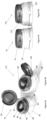
- FIG. 1A, 1B , 2A, 2B , 3A 3B, 4A and 4B there are shown two versions of a dispensing closure 10, 110.
- the closures 10, 110 comprise a pourer 15, 115 and a base 20, 120.
- the pourers 15, 115 comprise a pourer body 25, 125 and a lid 30, 130 joined together by a hinge 35, 135 (creating a "flip-top” pourer) that defines a "rear” or “back” of the pourer.
- the pourer is common (i.e. the same type of component) for both closures.
- the difference between the closures 10, 110, is the base, with the base 20 being a smaller diameter (e.g. 45mm) and the base 120 being a larger diameter (e.g. 50mm).
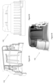
- Figure 5 is an exploded view of the closure of Figure 1B and shows the base 120 separated from the pourer 115, with the lid 130 shown in an open position with respect to the pourer body 125.
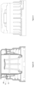
- the pourer 15, 115 is fitted into the base 20, 120 so as to be fixed axially but movable rotationally for (limited) rotational movement between a locked position ( Figures 6A, 7A ) and an unlocked position ( Figures 7A, 7B ).
- Figures 8A and 8B also shown the closure 10 in locked and unlocked positions.
- the lid 30, 130 In the locked position the lid 30, 130 cannot be lifted relative to the pourer body 25, 125. In the unlocked position the lid 30, 130 can be lifted, as illustrated in Figures 3A, 3B , 25 and 37 .
- a tamper-evidencing feature is activated (see Figures 3A and 3B ), providing visual evidence that the closure has already been opened with the lid is reclosed (illustrated in Figures 4A and 4B ).
- Figures 12 and 13 show the closure 10 in a locked and initially unopened configuration.
- Figures 14 to 19 show the closure 10 in an unlocked and unopened configuration.
- Figures 20 and 21 illustrate the closure as the lid is lifted.
- Figures 22 to 24 show the closure once the lid has been reclosed onto the pourer body.
- the base 20 comprises a generally cylindrical sidewall 40.
- the interior of the sidewall 20 is provided with a screw thread formation 21.
- a radially outwardly inclined wall portion 41 At one end of the sidewall 20 is a radially outwardly inclined wall portion 41. Depending from the portion 41 is an annular retention band 42.
- the band is connected to the portion by a first line of frangible bridges 43 and also by a single fixed, non-frangible bridge 44.
- a second line of frangible bridges is also formed beneath the bridge 44, being a chicane-like continuation of the first line of frangible bridges.
- the band 42 includes a segmented retention bead 46 so that in use the retention band 42 becomes fixed to a container neck so that the closure can be unscrewed but retained, as illustrated in Figure 38 . This means that an associated container 80 could be refilled.
- a radially inwardly inclined wall portion 46 At the other end of the sidewall 20 is a radially inwardly inclined wall portion 46.
- a terminal, axial wall portion 47 extends from the portion 46 and an annular top deck 48 extends orthogonally from the portion 47.
- a pourer retainer 49 depends from the top deck 48 into the interior of the base.
- An annular collar 50 upstands from the top deck 48.
- the pourer body 25 comprises an annular deck 26 and an annular side skirt 27 which depends from the periphery of the deck 26.
- the spout 28 includes an upstanding pouring lip 29.
- the spout 28 continues below the deck 26 with a cylindrical pourer wall 55.
- the wall 55 includes an exterior recess 56 into which the retainer 49 engages.
- the wall 55 includes a lower bead 57 so that the retainer 49 clips into the pourer body.
- the pourer body can rotate relative to the base but is axially restrained by engagement of the body 25 by the retainer 49.
- a frusto-conical flow regulator 58 projects through the interior of the wall 55.
- the regulator 58 includes a flow aperture 59 (also see Figure 3A ).
- the lid 30 comprises a flat top plate 31 and a depending lid skirt 32.
- the lid side skirt 32 provide a retention member 60 and two recess 61, 63 in which (in the initially unopened configuration) house tamper-evident tabs 62, 64.
- the tabs 62, 64 are connected to the recesses 61, 63 by frangible bridges 65.
- the deck 26 has three arcuate slots 67, 68, 69 which correspond with the member 60 and the tabs 62, 64.
- the tabs 62, 64 include retention hooks 70, 71.
- the member 60 includes a retention nose 72, which in the embodiment is formed with an undercut 73.
- the annular collar 50 includes a thinner portion 75 flanked by thicker portions 76, 77.
- the "front" of the collar 50 provides a locking area for the tamper-evident tabs and also a front locking area for the retention member.
- an outer arcuate collar 51 is provided and carries a block 52.
- the lid side skirt 32 is provided with a notch 33.
- the block 52 is positioned in the notch 33 and can be used to indicate if the closure is in the locked or unlocked position (for example c.f. Figures 6A and 6B ), as well as functioning as an end stop for the two positions (i.e. preventing further rotation between the pourer and the base).
- Figure 10A shows the lid rotated to the unlocked position and Figure 10B shows the lid rotated to the locked position.
- the lid can be rotated in either direction (clockwise or anticlockwise) to move from the locked position to the unlocked position.
- the retention member 60 In the locked position the retention member 60 is circumferentially aligned with a thicker portion of the collar. This means that if an attempt to lift the lid is made the member 60 cannot deflect radially and so the nose 72 cannot pass through the slot 68 - see Figure 12 .
- the member 60 When the pourer body is rotated to the unlocked position the member 60 then becomes circumferentially aligned with the thinner portion - see Figures 14 and 16 .
- the member 60 now has a space into which it can be deflected (radially inwards) by pushing it like a button - see Figure 20 .
- the tabs 62, 64 are circumferentially aligned with thicker portions of the collar - see Figure 17 and 19 , for example.
- the tab hooks 70, 71 engage under the front of the slots 67, 69. This causes the bridges 65 to break so that the tabs 62, 64 fall (irreversibly) into the slots - see Figures 3A and 22 to 24 .
- the recesses 61, 63 are now empty, providing visual evidence of opening of the lid.
- Figures 26 and 27 show the closure 110 in a locked and initially unopened configuration.
- Figures 28 to 33 show the closure 110 in an unlocked an unopened configuration.
- Figures 34 to 36 show the closure 110 once the lid has been reclosed onto the pourer body.
- the retainer 149 is the same as the retainer 49 and this means that the same pourer body can be used with either size of base.
- the locking/unlocking mechanism is the same as for the closure 10 and so is the tamper-evidence mechanisms.
- Figures 11A and 11B show a retention member formed according to a further embodiment.
- the retention member 260 is circumferentially aligned with a thicker collar portion 276. This means that if an attempt to lift the lid is made the member 260 cannot deflect radially and so the nose 272 cannot pass through the slot 268.
- the member 260 then becomes circumferentially aligned with the thinner portion 275 - see Figure 11B . This means that when the lid is lifted the member 260 now has a space into which it can deflect (radially inwards).
- the nose 272 presents a curved surface 274 (rather than an undercut) and so it can move through the slot 268 (by sliding over the peripheral wall 269) so that the lid can be moved to the open position i.e. it is not necessary for the retention member 260 to be manually pushed in to allow the retention member to be released from under the slot wall 269 (it automatically deflects and the lid is lifted).
- Figure 39 is a plan view of a container 280 formed in accordance with the present invention.
- the container 280 includes a neck 282 and a handle 284.
- the handle 284 includes a retention portion 285.
- Figure 40 shows the container of Figure 39 fitted with a flip-top dispensing closure 210.
- the closure 210 is shown with a lid 230 in an open position.
- the lid 230 clips (releasably) under the portion 285.
- the lid can be released from under the potion when it is to be closed.
- the closure may be a closure generally of the type discussed in relation to Figures 1 to 37 .
- Figure 41 shows a container 380 in combination with a closure 310.
- the closure 310 includes a lid 330 with a flat top plate 331.
- the handle 384 includes a flat 386.
- the top plate 331 and the handle flat 386 are in the same plane, meaning that stacking with other such containers is possible, as illustrated in Figure 44 (in this case shown with a dividing layer/sheet 390).
- FIGS 45 and 46 illustrate palletising of multiple container/closure packs 500 formed in accordance with the present invention.
- FIG. 45 illustrates palletising of multiple container/closure packs 500 formed in accordance with the present invention.
- FIG. 45 illustrates palletising of multiple container/closure packs 500 formed in accordance with the present invention.
- FIG. 45 illustrates palletising of multiple container/closure packs 500 formed in accordance with the present invention.
- FIG. 45 illustrates palletising of multiple container/closure packs 500 formed in accordance with the present invention.
Landscapes
- Engineering & Computer Science (AREA)
- Mechanical Engineering (AREA)
- Closures For Containers (AREA)
Applications Claiming Priority (1)
| Application Number | Priority Date | Filing Date | Title |
|---|---|---|---|
| GBGB2219321.3A GB202219321D0 (en) | 2022-12-20 | 2022-12-20 | Closure |
Publications (4)
| Publication Number | Publication Date |
|---|---|
| EP4389636A2 true EP4389636A2 (fr) | 2024-06-26 |
| EP4389636A3 EP4389636A3 (fr) | 2024-07-31 |
| EP4389636C0 EP4389636C0 (fr) | 2025-11-12 |
| EP4389636B1 EP4389636B1 (fr) | 2025-11-12 |
Family
ID=85035998
Family Applications (1)
| Application Number | Title | Priority Date | Filing Date |
|---|---|---|---|
| EP23218329.3A Active EP4389636B1 (fr) | 2022-12-20 | 2023-12-19 | Fermeture |
Country Status (2)
| Country | Link |
|---|---|
| EP (1) | EP4389636B1 (fr) |
| GB (1) | GB202219321D0 (fr) |
Cited By (2)
| Publication number | Priority date | Publication date | Assignee | Title |
|---|---|---|---|---|
| CN116692234A (zh) * | 2023-07-04 | 2023-09-05 | 四川省宜宾普什模具有限公司 | 运动盖 |
| CN120900831A (zh) * | 2025-09-30 | 2025-11-07 | 浙江赛豪实业有限公司 | 一种乳液泵 |
Family Cites Families (3)
| Publication number | Priority date | Publication date | Assignee | Title |
|---|---|---|---|---|
| US3773203A (en) * | 1972-01-20 | 1973-11-20 | Gilison Associates Inc | Closures for bottles and the like |
| ES1078137Y (es) * | 2012-10-30 | 2013-02-25 | Betapack Sa | Tapón con regulación de caudal |
| CH716564A1 (de) * | 2019-09-05 | 2021-03-15 | Alpla Werke Alwin Lehner Gmbh & Co Kg | Behälterverschluss zum Befestigen an einer Mündung eines Behälters und Behälter mit einem solchen Behälterverschluss. |
-
2022
- 2022-12-20 GB GBGB2219321.3A patent/GB202219321D0/en not_active Ceased
-
2023
- 2023-12-19 EP EP23218329.3A patent/EP4389636B1/fr active Active
Cited By (2)
| Publication number | Priority date | Publication date | Assignee | Title |
|---|---|---|---|---|
| CN116692234A (zh) * | 2023-07-04 | 2023-09-05 | 四川省宜宾普什模具有限公司 | 运动盖 |
| CN120900831A (zh) * | 2025-09-30 | 2025-11-07 | 浙江赛豪实业有限公司 | 一种乳液泵 |
Also Published As
| Publication number | Publication date |
|---|---|
| EP4389636C0 (fr) | 2025-11-12 |
| EP4389636A3 (fr) | 2024-07-31 |
| GB202219321D0 (en) | 2023-02-01 |
| EP4389636B1 (fr) | 2025-11-12 |
Similar Documents
| Publication | Publication Date | Title |
|---|---|---|
| US11993436B2 (en) | Container closure | |
| EP4389636A2 (fr) | Fermeture | |
| RU2094342C1 (ru) | Контейнер с крышкой | |
| US6543650B1 (en) | Double shell dispenser | |
| EP3950528B1 (fr) | Dispositif de bouchage destiné à être fixé sur le goulot d'un récipient | |
| US20210122532A1 (en) | Closure | |
| US5641099A (en) | Nestable pouring spout assembly | |
| US5915579A (en) | Container with tamper-evident and pre-lockable closure assembly | |
| EP4192753B1 (fr) | Fermeture de distribution de gouttes en deux parties | |
| EP2776335B1 (fr) | Fermeture inviolable | |
| WO2009010722A1 (fr) | Fermeture inviolable | |
| US7828166B1 (en) | Dispensing closure with child resistant feature | |
| CA3108563A1 (fr) | Bouchon en plastique attache | |
| CN114174188A (zh) | 封闭件 | |
| US12454395B2 (en) | Dispensing closure | |
| EP2925626B1 (fr) | Fermeture inviolable | |
| EP4095064B1 (fr) | Dispositif de bouchage destiné à être fixé au goulot d'un récipient et ensemble comprenant un récipient et un tel dispositif de bouchage | |
| WO2016096557A1 (fr) | Capuchon pour un contenant et emballage comportant un tel bouchon | |
| US20240132259A1 (en) | Spout Fitment With Removable Portion | |
| US11613412B2 (en) | Tethered plastic stopper | |
| EP2019048B1 (fr) | Fermeture | |
| AU2021388924A9 (en) | Assembly comprising a container and plugging device attached to the container | |
| EP4419444B1 (fr) | Fermeture inviolable | |
| US12397976B2 (en) | Flip-top closure and a package | |
| EP4626800A1 (fr) | Élément de fermeture |
Legal Events
| Date | Code | Title | Description |
|---|---|---|---|
| PUAI | Public reference made under article 153(3) epc to a published international application that has entered the european phase |
Free format text: ORIGINAL CODE: 0009012 |
|
| STAA | Information on the status of an ep patent application or granted ep patent |
Free format text: STATUS: THE APPLICATION HAS BEEN PUBLISHED |
|
| AK | Designated contracting states |
Kind code of ref document: A2 Designated state(s): AL AT BE BG CH CY CZ DE DK EE ES FI FR GB GR HR HU IE IS IT LI LT LU LV MC ME MK MT NL NO PL PT RO RS SE SI SK SM TR |
|
| PUAL | Search report despatched |
Free format text: ORIGINAL CODE: 0009013 |
|
| AK | Designated contracting states |
Kind code of ref document: A3 Designated state(s): AL AT BE BG CH CY CZ DE DK EE ES FI FR GB GR HR HU IE IS IT LI LT LU LV MC ME MK MT NL NO PL PT RO RS SE SI SK SM TR |
|
| RIC1 | Information provided on ipc code assigned before grant |
Ipc: B65D 23/10 20060101ALN20240627BHEP Ipc: B65D 55/16 20060101ALI20240627BHEP Ipc: B65D 47/08 20060101ALI20240627BHEP Ipc: B65D 47/04 20060101AFI20240627BHEP |
|
| P01 | Opt-out of the competence of the unified patent court (upc) registered |
Free format text: CASE NUMBER: APP_50166/2024 Effective date: 20240904 |
|
| STAA | Information on the status of an ep patent application or granted ep patent |
Free format text: STATUS: REQUEST FOR EXAMINATION WAS MADE |
|
| 17P | Request for examination filed |
Effective date: 20250109 |
|
| GRAP | Despatch of communication of intention to grant a patent |
Free format text: ORIGINAL CODE: EPIDOSNIGR1 |
|
| STAA | Information on the status of an ep patent application or granted ep patent |
Free format text: STATUS: GRANT OF PATENT IS INTENDED |
|
| RIC1 | Information provided on ipc code assigned before grant |
Ipc: B65D 23/10 20060101ALN20250513BHEP Ipc: B65D 55/16 20060101ALI20250513BHEP Ipc: B65D 47/08 20060101ALI20250513BHEP Ipc: B65D 47/04 20060101AFI20250513BHEP |
|
| INTG | Intention to grant announced |
Effective date: 20250610 |
|
| GRAS | Grant fee paid |
Free format text: ORIGINAL CODE: EPIDOSNIGR3 |
|
| GRAA | (expected) grant |
Free format text: ORIGINAL CODE: 0009210 |
|
| STAA | Information on the status of an ep patent application or granted ep patent |
Free format text: STATUS: THE PATENT HAS BEEN GRANTED |
|
| AK | Designated contracting states |
Kind code of ref document: B1 Designated state(s): AL AT BE BG CH CY CZ DE DK EE ES FI FR GB GR HR HU IE IS IT LI LT LU LV MC ME MK MT NL NO PL PT RO RS SE SI SK SM TR |
|
| REG | Reference to a national code |
Ref country code: CH Ref legal event code: F10 Free format text: ST27 STATUS EVENT CODE: U-0-0-F10-F00 (AS PROVIDED BY THE NATIONAL OFFICE) Effective date: 20251112 Ref country code: GB Ref legal event code: FG4D |
|
| REG | Reference to a national code |
Ref country code: IE Ref legal event code: FG4D |
|
| REG | Reference to a national code |
Ref country code: DE Ref legal event code: R096 Ref document number: 602023008538 Country of ref document: DE |
|
| PGFP | Annual fee paid to national office [announced via postgrant information from national office to epo] |
Ref country code: AT Payment date: 20260113 Year of fee payment: 3 |
|
| U01 | Request for unitary effect filed |
Effective date: 20251209 |
|
| U07 | Unitary effect registered |
Designated state(s): AT BE BG DE DK EE FI FR IT LT LU LV MT NL PT RO SE SI Effective date: 20251215 |
|
| P04 | Withdrawal of opt-out of the competence of the unified patent court (upc) registered |
Free format text: CASE NUMBER: APP_50166_1/2024 Effective date: 20251215 |
|
| U20 | Renewal fee for the european patent with unitary effect paid |
Year of fee payment: 3 Effective date: 20251223 |
|
| PG25 | Lapsed in a contracting state [announced via postgrant information from national office to epo] |
Ref country code: ES Free format text: LAPSE BECAUSE OF FAILURE TO SUBMIT A TRANSLATION OF THE DESCRIPTION OR TO PAY THE FEE WITHIN THE PRESCRIBED TIME-LIMIT Effective date: 20251112 |
|
| PG25 | Lapsed in a contracting state [announced via postgrant information from national office to epo] |
Ref country code: NO Free format text: LAPSE BECAUSE OF FAILURE TO SUBMIT A TRANSLATION OF THE DESCRIPTION OR TO PAY THE FEE WITHIN THE PRESCRIBED TIME-LIMIT Effective date: 20260212 |
|
| PG25 | Lapsed in a contracting state [announced via postgrant information from national office to epo] |
Ref country code: HR Free format text: LAPSE BECAUSE OF FAILURE TO SUBMIT A TRANSLATION OF THE DESCRIPTION OR TO PAY THE FEE WITHIN THE PRESCRIBED TIME-LIMIT Effective date: 20251112 |
|
| PG25 | Lapsed in a contracting state [announced via postgrant information from national office to epo] |
Ref country code: RS Free format text: LAPSE BECAUSE OF FAILURE TO SUBMIT A TRANSLATION OF THE DESCRIPTION OR TO PAY THE FEE WITHIN THE PRESCRIBED TIME-LIMIT Effective date: 20260212 |
|
| PG25 | Lapsed in a contracting state [announced via postgrant information from national office to epo] |
Ref country code: IS Free format text: LAPSE BECAUSE OF FAILURE TO SUBMIT A TRANSLATION OF THE DESCRIPTION OR TO PAY THE FEE WITHIN THE PRESCRIBED TIME-LIMIT Effective date: 20260312 |
|
| PG25 | Lapsed in a contracting state [announced via postgrant information from national office to epo] |
Ref country code: PL Free format text: LAPSE BECAUSE OF FAILURE TO SUBMIT A TRANSLATION OF THE DESCRIPTION OR TO PAY THE FEE WITHIN THE PRESCRIBED TIME-LIMIT Effective date: 20251112 |