EP4389923A1 - Hartmetallschneidwerkzeug - Google Patents
Hartmetallschneidwerkzeug Download PDFInfo
- Publication number
- EP4389923A1 EP4389923A1 EP22214877.7A EP22214877A EP4389923A1 EP 4389923 A1 EP4389923 A1 EP 4389923A1 EP 22214877 A EP22214877 A EP 22214877A EP 4389923 A1 EP4389923 A1 EP 4389923A1
- Authority
- EP
- European Patent Office
- Prior art keywords
- cemented carbide
- cutting tool
- binder
- weight fraction
- phase
- Prior art date
- Legal status (The legal status is an assumption and is not a legal conclusion. Google has not performed a legal analysis and makes no representation as to the accuracy of the status listed.)
- Granted
Links
Images


Classifications
-
- C—CHEMISTRY; METALLURGY
- C22—METALLURGY; FERROUS OR NON-FERROUS ALLOYS; TREATMENT OF ALLOYS OR NON-FERROUS METALS
- C22C—ALLOYS
- C22C29/00—Alloys based on carbides, oxides, nitrides, borides, or silicides, e.g. cermets, or other metal compounds, e.g. oxynitrides, sulfides
- C22C29/02—Alloys based on carbides, oxides, nitrides, borides, or silicides, e.g. cermets, or other metal compounds, e.g. oxynitrides, sulfides based on carbides or carbonitrides
- C22C29/06—Alloys based on carbides, oxides, nitrides, borides, or silicides, e.g. cermets, or other metal compounds, e.g. oxynitrides, sulfides based on carbides or carbonitrides based on carbides, but not containing other metal compounds
- C22C29/08—Alloys based on carbides, oxides, nitrides, borides, or silicides, e.g. cermets, or other metal compounds, e.g. oxynitrides, sulfides based on carbides or carbonitrides based on carbides, but not containing other metal compounds based on tungsten carbide
-
- B—PERFORMING OPERATIONS; TRANSPORTING
- B22—CASTING; POWDER METALLURGY
- B22F—WORKING METALLIC POWDER; MANUFACTURE OF ARTICLES FROM METALLIC POWDER; MAKING METALLIC POWDER; APPARATUS OR DEVICES SPECIALLY ADAPTED FOR METALLIC POWDER
- B22F3/00—Manufacture of workpieces or articles from metallic powder characterised by the manner of compacting or sintering; Apparatus specially adapted therefor ; Presses and furnaces
- B22F3/12—Both compacting and sintering
- B22F3/14—Both compacting and sintering simultaneously
- B22F3/15—Hot isostatic pressing
-
- C—CHEMISTRY; METALLURGY
- C22—METALLURGY; FERROUS OR NON-FERROUS ALLOYS; TREATMENT OF ALLOYS OR NON-FERROUS METALS
- C22C—ALLOYS
- C22C1/00—Making non-ferrous alloys
- C22C1/04—Making non-ferrous alloys by powder metallurgy
- C22C1/05—Mixtures of metal powder with non-metallic powder
- C22C1/051—Making hard metals based on borides, carbides, nitrides, oxides or silicides; Preparation of the powder mixture used as the starting material therefor
- C22C1/053—Making hard metals based on borides, carbides, nitrides, oxides or silicides; Preparation of the powder mixture used as the starting material therefor with in situ formation of hard compounds
- C22C1/055—Making hard metals based on borides, carbides, nitrides, oxides or silicides; Preparation of the powder mixture used as the starting material therefor with in situ formation of hard compounds using carbon
-
- C—CHEMISTRY; METALLURGY
- C22—METALLURGY; FERROUS OR NON-FERROUS ALLOYS; TREATMENT OF ALLOYS OR NON-FERROUS METALS
- C22C—ALLOYS
- C22C29/00—Alloys based on carbides, oxides, nitrides, borides, or silicides, e.g. cermets, or other metal compounds, e.g. oxynitrides, sulfides
- C22C29/02—Alloys based on carbides, oxides, nitrides, borides, or silicides, e.g. cermets, or other metal compounds, e.g. oxynitrides, sulfides based on carbides or carbonitrides
- C22C29/06—Alloys based on carbides, oxides, nitrides, borides, or silicides, e.g. cermets, or other metal compounds, e.g. oxynitrides, sulfides based on carbides or carbonitrides based on carbides, but not containing other metal compounds
- C22C29/067—Alloys based on carbides, oxides, nitrides, borides, or silicides, e.g. cermets, or other metal compounds, e.g. oxynitrides, sulfides based on carbides or carbonitrides based on carbides, but not containing other metal compounds comprising a particular metallic binder
-
- B—PERFORMING OPERATIONS; TRANSPORTING
- B22—CASTING; POWDER METALLURGY
- B22F—WORKING METALLIC POWDER; MANUFACTURE OF ARTICLES FROM METALLIC POWDER; MAKING METALLIC POWDER; APPARATUS OR DEVICES SPECIALLY ADAPTED FOR METALLIC POWDER
- B22F5/00—Manufacture of workpieces or articles from metallic powder characterised by the special shape of the product
- B22F2005/001—Cutting tools, earth boring or grinding tool other than table ware
-
- B—PERFORMING OPERATIONS; TRANSPORTING
- B22—CASTING; POWDER METALLURGY
- B22F—WORKING METALLIC POWDER; MANUFACTURE OF ARTICLES FROM METALLIC POWDER; MAKING METALLIC POWDER; APPARATUS OR DEVICES SPECIALLY ADAPTED FOR METALLIC POWDER
- B22F2998/00—Supplementary information concerning processes or compositions relating to powder metallurgy
- B22F2998/10—Processes characterised by the sequence of their steps
Definitions
- the present invention relates to a cutting tool comprising a cemented carbide substrate with a Fe- based binder, where the cemented carbide further comprising V, Cr and Ni.
- the invention also relates to a method of making such cutting tool.
- Cemented carbides based on WC with a cobalt binder have been known in the art for almost one hundred years.
- Other metals that are known as binder metals in cemented carbides are iron and nickel, however cobalt is by far the most used.
- Iron is a known binder element but is usually not preferred since it is considered to have a negative impact on the toughness of cemented carbides. Pure iron binders have a tendency to form brittle phases (i.e. martensite, Fe-carbides etc.). Additionally, the control of the carbon to produce a defect-free microstructure (precipitation of (W,Me)C subcarbides or graphite) is difficult to achieve in standard production.
- the present invention relates to a cutting tool comprising a cemented carbide substrate where the cemented carbide comprises a hard phase comprising WC, a mixed carbide phase and metal binder, where the cemented carbide comprises the elements V, Cr, Ni and Fe in such amounts so that:
- the cemented carbide according to the present invention have the advantage that the hardness can be varied while the toughness is basically maintained.
- Another advantage is that the WC grain size can be controlled since the grain growth during sintering is minimal partly due to the strong grain growth inhibitor effect of vanadium.
- the cemented carbide according to the present invention comprises WC, a mixed carbide phase and a metal binder where the mixed carbide phase will be formed during sintering.
- the exact composition of the mixed carbide phase is not completely known but can be described as a carbide phase with a particular stoichiometry which differs from the conventional gamma phase.
- the mixed carbide phase has a crystal structure similar to eta phase, however, eta phase usually contains large amounts of the binder metal.
- the mixed carbide phase contains small amounts of Fe, see EDX analysis in the examples. More specifically the phases can be one or more of these elements with atomic ratio V:W from 3:1 to 3:2, in the (V,W) x C y phase.
- the metal binder can also comprise smaller amounts of other elements present in the cemented carbide that will inevitably dissolve in the metal binder during sintering.
- the total amount of the elements Fe, Cr and Ni in the metal binder is at least 90 wt% of the binder, preferably at least 95 wt% of the binder.
- the binder can also comprise other elements, e.g. W present in the cemented carbide which is dissolved in the binder during sintering.
- the amount of metal binder in the cemented carbide is preferably between 3 and 20 wt% of the cemented carbide, more preferably between 5 and 15 wt%.
- One way to determine the amount of metal binder is by image analysis or by chemical analysis of the cemented carbide composition.
- the cemented carbide comprises V in such amount that the weight fraction V/(V+Cr+Ni+Fe) is between 0.0030 and 0.050, preferably between 0.010 and 0.030 and more preferably between 0.015 and 0.020. If the V content is too low, the WC grain growth during sintering will increase and if the V content is too high, the cemented carbide will rapidly decrease in toughness, causing embrittlement at WC interfaces.
- the cemented carbide comprises Cr in such amount that the weight fraction Cr/(V+Cr+Ni+Fe) is between 0.010 and 0.040, preferably between 0.010 and 0.020. If the Cr content is too low, the solid solution strengthening effect of Cr in Fe will decrease leading to low hardness-toughness combinations; and if the Cr content is too high, the cemented carbide will form Cr-carbide precipitation at grain boundaries, worsening the properties of the material.
- the cemented carbide comprises Ni in such amount that the weight fraction Ni/(V+Cr+Ni+Fe) is between 0.020 and less than 0.050, preferably between 0.020 and 0.045, more preferably between 0.020 and 0.030. If the Ni content is too low, the binder of the cemented carbide will present less ductility, leading to fragilization of the composite and if the Ni content is too high, the cemented carbide will decrease its strength and temperature stability to heat exposure.
- the cemented carbide comprises Fe in such amount that the weight fraction Fe/(V+Cr+Ni+Fe) is between 0.860 and 0.967, preferably between 0.910 and 0.960.
- the cemented carbide comprises no other components other than W, C, Fe, Ni, Cr and V, except for unavoidable impurities. By that is meant that no other elements are added as raw materials.
- the cemented carbide may be essentially free from Co and by that is herein meant that no Co is added as raw material and that Co is present in the cemented carbide on a level of impurity, preferably below 1 wt%, more preferably below 0.5 wt%. Small amounts of Co are usually detected since some manufacturing equipment, like e.g. milling bodies, contains Co containing cemented carbide and can give a small contribution to the overall composition.
- the hard phase comprises at least 50 wt% WC.
- the average grain size of the WC is suitably between 0.2 and 10 ⁇ m, preferably between 0.2 and 5 ⁇ m.
- the average grain size of the WC can e.g. be measured by using a mean linear intercept method on a SEM/LOM image.
- the cemented carbide can also contain other constituents common in the art of cemented carbides, e.g. carbides, carbonitrides or nitrides of one or more of Ti, Ta and Nb. Elements from those carbides will then inevitably be dissolved in the binder during sintering.
- cemented carbides e.g. carbides, carbonitrides or nitrides of one or more of Ti, Ta and Nb. Elements from those carbides will then inevitably be dissolved in the binder during sintering.
- the cemented carbide substrate is provided with a wear resistant CVD (Chemical vapor deposition) or PVD (Physical vapor deposition) coating.
- the cemented carbide substrate is provided with a wear resistant PVD coating, suitably being a nitride, oxide, carbide or mixtures thereof of one or more of the elements selected from groups 4, 5 and 6 in the periodic table and optionally with Al and/or Si.
- a wear resistant PVD coating suitably being a nitride, oxide, carbide or mixtures thereof of one or more of the elements selected from groups 4, 5 and 6 in the periodic table and optionally with Al and/or Si.
- the cemented carbide substrate is provided with a wear resistant CVD coating.
- the cemented carbide substrate is provided with a wear resistant CVD coating comprising several layers, suitably at least a carbonitride layer and an Al 2 O 3 layer.
- cutting tool is herein meant a cutting tool insert, end mill or drill.
- the present invention also relates to a method of making a cutting tool according to the above comprising a cemented carbide substrate as described above.
- the method comprises the following steps:
- the raw materials comprising the elements V, Fe, Ni and Cr can be added as pure metals, alloys of two or more metals or as carbides, nitrides or carbonitrides thereof.
- the raw materials should be added in such amounts so that the binder phase, after sintering will have the composition as has been described above.
- the powders are VC, Cr 3 C 2 , Fe and Ni.
- the milling liquid is preferably water, alcohol or an organic solvent, more preferably water or a water and alcohol mixture and most preferably a water and ethanol mixture.
- the properties of the slurry are dependent on the amount of milling liquid added. Since the drying of the slurry requires energy, the amount of liquid should be minimized to keep costs down. However, enough liquid needs to be added to achieve a pumpable slurry and avoid clogging of the system. Also, other compounds commonly known in the art can be added to the slurry e.g. dispersion agents, pH-adjusters etc.
- An organic binder is also optionally added to the slurry in order to facilitate the granulation during the following spray drying operation but also to function as a pressing agent for any following pressing and sintering operations.
- the organic binder can be any binder commonly used in the art.
- the organic binder can e.g. be paraffin, polyethylene glycol (PEG), long chain fatty acids etc.
- the amount of organic binder is suitably between 15 and 25 vol% based on the total dry powder volume, the amount of organic binder is not included in the total dry powder volume.
- the slurry comprising powders forming hard constituents and powders forming the binder phase, and possibly an organic binder is suitably mixed by a milling operation, either in a ball mill or attritor mill.
- the milling is suitably made by first forming a slurry comprising metal binder powder, the first and second powder fraction, and possibly an organic binder. Then the slurry is suitably milled in a ball mill or attritor mill to obtain a homogenous slurry blend.
- the slurry containing the powdered materials mixed with the organic liquid and possibly the organic binder is atomized through an appropriate nozzle in the drying tower where the small drops are instantaneously dried by a stream of hot gas, for instance in a stream of nitrogen, to form agglomerated granules.
- a stream of hot gas for instance in a stream of nitrogen
- other drying methods can be used, e.g. pan drying.
- Green bodies are subsequently formed from the dried powders/granules by a pressing operation such as uniaxial pressing, multiaxial pressing etc.
- the green bodies formed from the powders/granules made according to the present invention is subsequently sintered according to any conventional sintering methods e.g. vacuum sintering, Sinter HIP, spark plasma sintering, gas pressure sintering (GPS) etc.
- any conventional sintering methods e.g. vacuum sintering, Sinter HIP, spark plasma sintering, gas pressure sintering (GPS) etc.
- the sintering temperature is between 1350 and 1550°C.
- the sintering process is sinter HIP performed at a temperature of between 1350 and 1550°C, and a pressure of at least 40 Bar, preferably between 40 and 80 Bar.
- the cemented carbide substrates are provided with a coating.
- the cemented carbide substrates made according to the above are provided with a wear resistant coating using CVD or PVD-technique.
- the cemented carbide substrate is provided with a wear resistant PVD coating, suitably being a nitride, oxide, carbide or mixtures thereof of one or more of the elements selected from groups 4, 5 and 6 in the periodic table and optionally with Al and/or Si.
- a wear resistant PVD coating suitably being a nitride, oxide, carbide or mixtures thereof of one or more of the elements selected from groups 4, 5 and 6 in the periodic table and optionally with Al and/or Si.
- a CVD coating is deposited comprising a first TiCN layer deposited by MTCVD and a second ⁇ -Al 2 O 3 layer deposited by CVD. Possibly an outermost color layer for wear detection, e.g. a TiN layer, can also be deposited.
- the coating can also be subjected to additional treatments, such as brushing, blasting etc.
- the present invention also discloses a cemented carbide cutting tool made according to the method described above.
- Cemented carbides were prepared from raw materials being Cr 3 C 2 , VC, Ni and Fe in amounts so that the composition of the total powder, excluding the WC, was 91wt% Fe, 3.5 wt% Ni, 1.4 wt% Cr and 4.0 wt% V. Carbon black was added up to 0.4% of mixture weight, more specifically between 0.15 and 0.4%.
- the WC powder had an average particle size of 0.83 ⁇ m (FSSS).
- the amount of V+Cr+Ni+Fe in the cemented carbide was varied in accordance with Table 1.
- the raw material powders were milled in a ball mill for 8 h together with an organic binder (2 wt% PEG based on total powder weight) and a milling liquid (water/ethanol) to form a slurry which was dried and milled in agate mortar to obtain a powder blend.
- the powder was pressed into green bodies.
- the green bodies were sintered in a HIP (hot isostatic pressure) furnace where maximum sintering temperature was 1450°C and sintering time was 1 h at 40 mbar vacuum sintering followed by 15 min 50 bar highpressure step to reduce porosity of the samples.
- HIP hot isostatic pressure
- the toughness (K1C) and the hardness (HV30) were measured on the sintered bodies after grinding and polishing.
- the HV30 has been measured according to ASTM B294.
- the fracture toughness, K1C has been measured according to Shetty.
- Table 1 V+Cr+Ni+Fe (wt% of total cemented carbide) Sintering temperature (°C) K1C (MPa/m) HV30 Invention 1 10.4 1410 8.26 1850 Invention 2 9.0 1450 8.09 1909 Invention 3 7.8 1450 8.24 2007 Invention 4 6.5 1450 7.86 2115 Invention 5 10.3 1410 8.06 1828 Invention 6 12.4 1410 8.04 1724 Invention 7 14.5 1410 7.82 1636 Invention 8 16.5 1410 7.87 1527
- the cemented carbides according to the present invention have hardness and toughness properties in the same range as cemented carbides having a Co binder.
- Powders with variation in V content was prepared in the same manner from the same raw material as in Example 1 with the compositions according to Table 2.
- the samples were sintered in a HIP furnace at 3 different temperatures (1410, 1450 and 1500°C), see Table 2. Sintering time is 60 min at highest temperature vacuum sintering 40 mbar followed by 15 min high pressure sintering with 50 bar.
- the samples from Example 2 were analyzed using XRD.
- the samples were prepared by casting in bakelite, grinding and polishing.
- the X-ray source was operated at 50 kV and 1 mA.
- the sample was mounted with adhesive tape to the sample holder.
- a collimator size of 1.0 mm diameter was used in all experiments. Measurements were conducted at a polished side of the investigated insert. Data were collected in the 2 ⁇ range 10°-140°.
- the XRD data were analyzed with software DIFFRAC EVA (Bruker) and High Score Plus (Malvern Panalytical).
- a XRD diffractogram is shown where the peak for the WC is marked and also 3 peaks for the mixed carbide phase are shown.
- the XRD diffractogram of samples with different V content clearly shows that the peaks indicating the mixed carbide are increasing with increased V content.
- Invention 5 from Table 1 and two additional samples according to the invention, Invention 9 and Invention 10.
- Invention 9 and Invention 10 were made in the same manner as in Example 1 and where Invention 9 and Invention 10 contained 7.7 wt% and 16.5 wt% of the same Fe-V-Ni-Cr mixture as in Example 1, respectively.
- the same WC raw material as in Example 1 was used for Invention 9, whereas a WC raw material having a particle size of 7.15 ⁇ m (FSSS) was used.
- FSSS WC raw material having a particle size of 7.15 ⁇ m
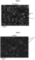
- the mixed carbide phase contains mainly W; C and V but only small amounts of Fe, NI and Cr.
Landscapes
- Chemical & Material Sciences (AREA)
- Engineering & Computer Science (AREA)
- Mechanical Engineering (AREA)
- Materials Engineering (AREA)
- Metallurgy (AREA)
- Organic Chemistry (AREA)
- Manufacturing & Machinery (AREA)
- Powder Metallurgy (AREA)
- Cutting Tools, Boring Holders, And Turrets (AREA)
Priority Applications (5)
| Application Number | Priority Date | Filing Date | Title |
|---|---|---|---|
| EP22214877.7A EP4389923B1 (de) | 2022-12-20 | 2022-12-20 | Hartmetallschneidwerkzeug und verfahren zu dessen herstellung |
| JP2025535262A JP2025541879A (ja) | 2022-12-20 | 2023-12-05 | 超硬合金切削工具 |
| PCT/EP2023/084231 WO2024132488A1 (en) | 2022-12-20 | 2023-12-05 | A cemented carbide cutting tool |
| CN202380086319.8A CN120344683A (zh) | 2022-12-20 | 2023-12-05 | 硬质合金切削刀具 |
| KR1020257020580A KR20250128975A (ko) | 2022-12-20 | 2023-12-05 | 초경합금 절삭 공구 |
Applications Claiming Priority (1)
| Application Number | Priority Date | Filing Date | Title |
|---|---|---|---|
| EP22214877.7A EP4389923B1 (de) | 2022-12-20 | 2022-12-20 | Hartmetallschneidwerkzeug und verfahren zu dessen herstellung |
Publications (2)
| Publication Number | Publication Date |
|---|---|
| EP4389923A1 true EP4389923A1 (de) | 2024-06-26 |
| EP4389923B1 EP4389923B1 (de) | 2025-05-21 |
Family
ID=84541459
Family Applications (1)
| Application Number | Title | Priority Date | Filing Date |
|---|---|---|---|
| EP22214877.7A Active EP4389923B1 (de) | 2022-12-20 | 2022-12-20 | Hartmetallschneidwerkzeug und verfahren zu dessen herstellung |
Country Status (5)
| Country | Link |
|---|---|
| EP (1) | EP4389923B1 (de) |
| JP (1) | JP2025541879A (de) |
| KR (1) | KR20250128975A (de) |
| CN (1) | CN120344683A (de) |
| WO (1) | WO2024132488A1 (de) |
Cited By (1)
| Publication number | Priority date | Publication date | Assignee | Title |
|---|---|---|---|---|
| EP4700141A1 (de) * | 2024-08-22 | 2026-02-25 | AB Sandvik Coromant | Beschichtetes schneidwerkzeug |
Citations (3)
| Publication number | Priority date | Publication date | Assignee | Title |
|---|---|---|---|---|
| US20180142331A1 (en) * | 2016-11-10 | 2018-05-24 | U.S. Army Research Laboratory Attn: Rdrl-Loc-I | Cemented carbide containing tungsten carbide and finegrained iron alloy binder |
| US20190194783A1 (en) * | 2016-08-01 | 2019-06-27 | Hitachi Metals, Ltd. | Cemented carbide and its production method, and rolling roll |
| EP3885459A1 (de) * | 2020-03-26 | 2021-09-29 | CERATIZIT Luxembourg S.à r.l. | Kobaltfreier wolframkarbid-basierter hartmetallwerkstoff |
-
2022
- 2022-12-20 EP EP22214877.7A patent/EP4389923B1/de active Active
-
2023
- 2023-12-05 CN CN202380086319.8A patent/CN120344683A/zh active Pending
- 2023-12-05 WO PCT/EP2023/084231 patent/WO2024132488A1/en not_active Ceased
- 2023-12-05 KR KR1020257020580A patent/KR20250128975A/ko active Pending
- 2023-12-05 JP JP2025535262A patent/JP2025541879A/ja active Pending
Patent Citations (3)
| Publication number | Priority date | Publication date | Assignee | Title |
|---|---|---|---|---|
| US20190194783A1 (en) * | 2016-08-01 | 2019-06-27 | Hitachi Metals, Ltd. | Cemented carbide and its production method, and rolling roll |
| US20180142331A1 (en) * | 2016-11-10 | 2018-05-24 | U.S. Army Research Laboratory Attn: Rdrl-Loc-I | Cemented carbide containing tungsten carbide and finegrained iron alloy binder |
| EP3885459A1 (de) * | 2020-03-26 | 2021-09-29 | CERATIZIT Luxembourg S.à r.l. | Kobaltfreier wolframkarbid-basierter hartmetallwerkstoff |
Cited By (2)
| Publication number | Priority date | Publication date | Assignee | Title |
|---|---|---|---|---|
| EP4700141A1 (de) * | 2024-08-22 | 2026-02-25 | AB Sandvik Coromant | Beschichtetes schneidwerkzeug |
| WO2026041599A1 (en) * | 2024-08-22 | 2026-02-26 | Ab Sandvik Coromant | Coated cutting tool |
Also Published As
| Publication number | Publication date |
|---|---|
| CN120344683A (zh) | 2025-07-18 |
| WO2024132488A1 (en) | 2024-06-27 |
| JP2025541879A (ja) | 2025-12-23 |
| EP4389923B1 (de) | 2025-05-21 |
| KR20250128975A (ko) | 2025-08-28 |
Similar Documents
| Publication | Publication Date | Title |
|---|---|---|
| US11213892B2 (en) | Cemented carbide with alternative binder | |
| US11162161B2 (en) | Cutting tool | |
| US11850663B2 (en) | Cemented carbide with alternative binder | |
| US12005507B2 (en) | Cemented carbide and cutting tool including same as substrate | |
| WO2021122520A1 (en) | Gradient cemented carbide with alternative binder | |
| EP3839086A1 (de) | Hartmetall und beschichtetes hartmetall und werkzeug damit | |
| EP4389923A1 (de) | Hartmetallschneidwerkzeug | |
| EP4713161A1 (de) | Schneidwerkzeug | |
| EP4438753A1 (de) | Schneidwerkzeug | |
| EP4700141A1 (de) | Beschichtetes schneidwerkzeug | |
| RU2771728C1 (ru) | Твердый сплав с альтернативным связующим | |
| JP2022130147A (ja) | 切削工具 | |
| JP2022133540A (ja) | 切削工具 |
Legal Events
| Date | Code | Title | Description |
|---|---|---|---|
| PUAI | Public reference made under article 153(3) epc to a published international application that has entered the european phase |
Free format text: ORIGINAL CODE: 0009012 |
|
| STAA | Information on the status of an ep patent application or granted ep patent |
Free format text: STATUS: THE APPLICATION HAS BEEN PUBLISHED |
|
| AK | Designated contracting states |
Kind code of ref document: A1 Designated state(s): AL AT BE BG CH CY CZ DE DK EE ES FI FR GB GR HR HU IE IS IT LI LT LU LV MC ME MK MT NL NO PL PT RO RS SE SI SK SM TR |
|
| STAA | Information on the status of an ep patent application or granted ep patent |
Free format text: STATUS: REQUEST FOR EXAMINATION WAS MADE |
|
| 17P | Request for examination filed |
Effective date: 20250102 |
|
| GRAP | Despatch of communication of intention to grant a patent |
Free format text: ORIGINAL CODE: EPIDOSNIGR1 |
|
| STAA | Information on the status of an ep patent application or granted ep patent |
Free format text: STATUS: GRANT OF PATENT IS INTENDED |
|
| RIC1 | Information provided on ipc code assigned before grant |
Ipc: B22F 5/00 20060101ALN20250131BHEP Ipc: B22F 3/15 20060101ALI20250131BHEP Ipc: C22C 29/08 20060101ALI20250131BHEP Ipc: C22C 29/06 20060101ALI20250131BHEP Ipc: C22C 1/055 20230101AFI20250131BHEP |
|
| INTG | Intention to grant announced |
Effective date: 20250226 |
|
| GRAS | Grant fee paid |
Free format text: ORIGINAL CODE: EPIDOSNIGR3 |
|
| GRAA | (expected) grant |
Free format text: ORIGINAL CODE: 0009210 |
|
| STAA | Information on the status of an ep patent application or granted ep patent |
Free format text: STATUS: THE PATENT HAS BEEN GRANTED |
|
| AK | Designated contracting states |
Kind code of ref document: B1 Designated state(s): AL AT BE BG CH CY CZ DE DK EE ES FI FR GB GR HR HU IE IS IT LI LT LU LV MC ME MK MT NL NO PL PT RO RS SE SI SK SM TR |
|
| P01 | Opt-out of the competence of the unified patent court (upc) registered |
Free format text: CASE NUMBER: APP_17571/2025 Effective date: 20250410 |
|
| REG | Reference to a national code |
Ref country code: GB Ref legal event code: FG4D |
|
| REG | Reference to a national code |
Ref country code: CH Ref legal event code: EP |
|
| REG | Reference to a national code |
Ref country code: DE Ref legal event code: R096 Ref document number: 602022014927 Country of ref document: DE |
|
| REG | Reference to a national code |
Ref country code: IE Ref legal event code: FG4D |
|
| REG | Reference to a national code |
Ref country code: NL Ref legal event code: MP Effective date: 20250521 |
|
| PG25 | Lapsed in a contracting state [announced via postgrant information from national office to epo] |
Ref country code: FI Free format text: LAPSE BECAUSE OF FAILURE TO SUBMIT A TRANSLATION OF THE DESCRIPTION OR TO PAY THE FEE WITHIN THE PRESCRIBED TIME-LIMIT Effective date: 20250521 Ref country code: PT Free format text: LAPSE BECAUSE OF FAILURE TO SUBMIT A TRANSLATION OF THE DESCRIPTION OR TO PAY THE FEE WITHIN THE PRESCRIBED TIME-LIMIT Effective date: 20250922 Ref country code: ES Free format text: LAPSE BECAUSE OF FAILURE TO SUBMIT A TRANSLATION OF THE DESCRIPTION OR TO PAY THE FEE WITHIN THE PRESCRIBED TIME-LIMIT Effective date: 20250521 |
|
| REG | Reference to a national code |
Ref country code: LT Ref legal event code: MG9D |
|
| PG25 | Lapsed in a contracting state [announced via postgrant information from national office to epo] |
Ref country code: NO Free format text: LAPSE BECAUSE OF FAILURE TO SUBMIT A TRANSLATION OF THE DESCRIPTION OR TO PAY THE FEE WITHIN THE PRESCRIBED TIME-LIMIT Effective date: 20250821 Ref country code: GR Free format text: LAPSE BECAUSE OF FAILURE TO SUBMIT A TRANSLATION OF THE DESCRIPTION OR TO PAY THE FEE WITHIN THE PRESCRIBED TIME-LIMIT Effective date: 20250822 |
|
| PG25 | Lapsed in a contracting state [announced via postgrant information from national office to epo] |
Ref country code: NL Free format text: LAPSE BECAUSE OF FAILURE TO SUBMIT A TRANSLATION OF THE DESCRIPTION OR TO PAY THE FEE WITHIN THE PRESCRIBED TIME-LIMIT Effective date: 20250521 Ref country code: PL Free format text: LAPSE BECAUSE OF FAILURE TO SUBMIT A TRANSLATION OF THE DESCRIPTION OR TO PAY THE FEE WITHIN THE PRESCRIBED TIME-LIMIT Effective date: 20250521 |
|
| PG25 | Lapsed in a contracting state [announced via postgrant information from national office to epo] |
Ref country code: BG Free format text: LAPSE BECAUSE OF FAILURE TO SUBMIT A TRANSLATION OF THE DESCRIPTION OR TO PAY THE FEE WITHIN THE PRESCRIBED TIME-LIMIT Effective date: 20250521 |
|
| PG25 | Lapsed in a contracting state [announced via postgrant information from national office to epo] |
Ref country code: HR Free format text: LAPSE BECAUSE OF FAILURE TO SUBMIT A TRANSLATION OF THE DESCRIPTION OR TO PAY THE FEE WITHIN THE PRESCRIBED TIME-LIMIT Effective date: 20250521 |
|
| PG25 | Lapsed in a contracting state [announced via postgrant information from national office to epo] |
Ref country code: RS Free format text: LAPSE BECAUSE OF FAILURE TO SUBMIT A TRANSLATION OF THE DESCRIPTION OR TO PAY THE FEE WITHIN THE PRESCRIBED TIME-LIMIT Effective date: 20250821 |
|
| PG25 | Lapsed in a contracting state [announced via postgrant information from national office to epo] |
Ref country code: IS Free format text: LAPSE BECAUSE OF FAILURE TO SUBMIT A TRANSLATION OF THE DESCRIPTION OR TO PAY THE FEE WITHIN THE PRESCRIBED TIME-LIMIT Effective date: 20250921 |
|
| PG25 | Lapsed in a contracting state [announced via postgrant information from national office to epo] |
Ref country code: LV Free format text: LAPSE BECAUSE OF FAILURE TO SUBMIT A TRANSLATION OF THE DESCRIPTION OR TO PAY THE FEE WITHIN THE PRESCRIBED TIME-LIMIT Effective date: 20250521 |
|
| REG | Reference to a national code |
Ref country code: AT Ref legal event code: MK05 Ref document number: 1796808 Country of ref document: AT Kind code of ref document: T Effective date: 20250521 |
|
| PGFP | Annual fee paid to national office [announced via postgrant information from national office to epo] |
Ref country code: DE Payment date: 20251028 Year of fee payment: 4 |
|
| PG25 | Lapsed in a contracting state [announced via postgrant information from national office to epo] |
Ref country code: AT Free format text: LAPSE BECAUSE OF FAILURE TO SUBMIT A TRANSLATION OF THE DESCRIPTION OR TO PAY THE FEE WITHIN THE PRESCRIBED TIME-LIMIT Effective date: 20250521 Ref country code: DK Free format text: LAPSE BECAUSE OF FAILURE TO SUBMIT A TRANSLATION OF THE DESCRIPTION OR TO PAY THE FEE WITHIN THE PRESCRIBED TIME-LIMIT Effective date: 20250521 Ref country code: SM Free format text: LAPSE BECAUSE OF FAILURE TO SUBMIT A TRANSLATION OF THE DESCRIPTION OR TO PAY THE FEE WITHIN THE PRESCRIBED TIME-LIMIT Effective date: 20250521 |
|
| PGFP | Annual fee paid to national office [announced via postgrant information from national office to epo] |
Ref country code: FR Payment date: 20251124 Year of fee payment: 4 |
|
| PG25 | Lapsed in a contracting state [announced via postgrant information from national office to epo] |
Ref country code: CZ Free format text: LAPSE BECAUSE OF FAILURE TO SUBMIT A TRANSLATION OF THE DESCRIPTION OR TO PAY THE FEE WITHIN THE PRESCRIBED TIME-LIMIT Effective date: 20250521 |
|
| PG25 | Lapsed in a contracting state [announced via postgrant information from national office to epo] |
Ref country code: EE Free format text: LAPSE BECAUSE OF FAILURE TO SUBMIT A TRANSLATION OF THE DESCRIPTION OR TO PAY THE FEE WITHIN THE PRESCRIBED TIME-LIMIT Effective date: 20250521 |
|
| PG25 | Lapsed in a contracting state [announced via postgrant information from national office to epo] |
Ref country code: SK Free format text: LAPSE BECAUSE OF FAILURE TO SUBMIT A TRANSLATION OF THE DESCRIPTION OR TO PAY THE FEE WITHIN THE PRESCRIBED TIME-LIMIT Effective date: 20250521 |
|
| REG | Reference to a national code |
Ref country code: DE Ref legal event code: R097 Ref document number: 602022014927 Country of ref document: DE |
|
| PG25 | Lapsed in a contracting state [announced via postgrant information from national office to epo] |
Ref country code: RO Free format text: LAPSE BECAUSE OF FAILURE TO SUBMIT A TRANSLATION OF THE DESCRIPTION OR TO PAY THE FEE WITHIN THE PRESCRIBED TIME-LIMIT Effective date: 20250521 |
|
| PLBE | No opposition filed within time limit |
Free format text: ORIGINAL CODE: 0009261 |
|
| STAA | Information on the status of an ep patent application or granted ep patent |
Free format text: STATUS: NO OPPOSITION FILED WITHIN TIME LIMIT |
|
| REG | Reference to a national code |
Ref country code: CH Ref legal event code: L10 Free format text: ST27 STATUS EVENT CODE: U-0-0-L10-L00 (AS PROVIDED BY THE NATIONAL OFFICE) Effective date: 20260402 |
|
| PGFP | Annual fee paid to national office [announced via postgrant information from national office to epo] |
Ref country code: IT Payment date: 20251231 Year of fee payment: 4 |