EP4390019A1 - Anordnung zum öffnen und/oder schliessen einer fahrzeugtür - Google Patents
Anordnung zum öffnen und/oder schliessen einer fahrzeugtür Download PDFInfo
- Publication number
- EP4390019A1 EP4390019A1 EP22214720.9A EP22214720A EP4390019A1 EP 4390019 A1 EP4390019 A1 EP 4390019A1 EP 22214720 A EP22214720 A EP 22214720A EP 4390019 A1 EP4390019 A1 EP 4390019A1
- Authority
- EP
- European Patent Office
- Prior art keywords
- vehicle door
- switch
- grip member
- assembly
- attached
- Prior art date
- Legal status (The legal status is an assumption and is not a legal conclusion. Google has not performed a legal analysis and makes no representation as to the accuracy of the status listed.)
- Pending
Links
Images


Classifications
-
- E—FIXED CONSTRUCTIONS
- E05—LOCKS; KEYS; WINDOW OR DOOR FITTINGS; SAFES
- E05B—LOCKS; ACCESSORIES THEREFOR; HANDCUFFS
- E05B81/00—Power-actuated vehicle locks
- E05B81/54—Electrical circuits
- E05B81/64—Monitoring or sensing, e.g. by using switches or sensors
- E05B81/76—Detection of handle operation; Detection of a user approaching a handle; Electrical switching actions performed by door handles
- E05B81/77—Detection of handle operation; Detection of a user approaching a handle; Electrical switching actions performed by door handles comprising sensors detecting the presence of the hand of a user
-
- E—FIXED CONSTRUCTIONS
- E05—LOCKS; KEYS; WINDOW OR DOOR FITTINGS; SAFES
- E05B—LOCKS; ACCESSORIES THEREFOR; HANDCUFFS
- E05B85/00—Details of vehicle locks not provided for in groups E05B77/00 - E05B83/00
- E05B85/10—Handles
-
- B—PERFORMING OPERATIONS; TRANSPORTING
- B60—VEHICLES IN GENERAL
- B60J—WINDOWS, WINDSCREENS, NON-FIXED ROOFS, DOORS, OR SIMILAR DEVICES FOR VEHICLES; REMOVABLE EXTERNAL PROTECTIVE COVERINGS SPECIALLY ADAPTED FOR VEHICLES
- B60J5/00—Doors
-
- E—FIXED CONSTRUCTIONS
- E05—LOCKS; KEYS; WINDOW OR DOOR FITTINGS; SAFES
- E05B—LOCKS; ACCESSORIES THEREFOR; HANDCUFFS
- E05B17/00—Accessories in connection with locks
- E05B17/10—Illuminating devices on or for locks or keys; Transparent or translucent lock parts; Indicator lights
-
- E—FIXED CONSTRUCTIONS
- E05—LOCKS; KEYS; WINDOW OR DOOR FITTINGS; SAFES
- E05B—LOCKS; ACCESSORIES THEREFOR; HANDCUFFS
- E05B79/00—Mounting or connecting vehicle locks or parts thereof
- E05B79/02—Mounting of vehicle locks or parts thereof
-
- E—FIXED CONSTRUCTIONS
- E05—LOCKS; KEYS; WINDOW OR DOOR FITTINGS; SAFES
- E05B—LOCKS; ACCESSORIES THEREFOR; HANDCUFFS
- E05B79/00—Mounting or connecting vehicle locks or parts thereof
- E05B79/02—Mounting of vehicle locks or parts thereof
- E05B79/06—Mounting of handles, e.g. to the wing or to the lock
-
- E—FIXED CONSTRUCTIONS
- E05—LOCKS; KEYS; WINDOW OR DOOR FITTINGS; SAFES
- E05B—LOCKS; ACCESSORIES THEREFOR; HANDCUFFS
- E05B81/00—Power-actuated vehicle locks
- E05B81/54—Electrical circuits
- E05B81/64—Monitoring or sensing, e.g. by using switches or sensors
- E05B81/76—Detection of handle operation; Detection of a user approaching a handle; Electrical switching actions performed by door handles
Definitions
- the present invention relates to an assembly for opening and/or closing a vehicle door, a vehicle door comprising said assembly and a method of mounting said assembly on a vehicle door.
- Electronic assemblies for opening and/or closing a vehicle door generally comprise a handle and electronic means configured to unlock the vehicle door and to activate a latch, such as an electronic latch, to open the vehicle door.
- the invention concerns an assembly for opening and/or closing a vehicle door the assembly comprising :
- the electronic switch subassembly comprising a switch contact area, facing towards the external side of the vehicle door when the grip member is attached to the external side of the vehicle door.
- the switch contact area Due to the switch contact area arranged so as to face towards the vehicle door when the grip member is attached to the external side of the vehicle door, the switch contact area is easily and intuitively reachable by the user's hand when the user grabs the handle.
- the assembly for opening and/or closing a vehicle door can comprise the following features, considered alone or in any technically possible combination.
- the gripping part comprises a traction surface configured to allow exerting a traction on the grip member so as to pull on the vehicle door, the traction surface facing the vehicle door when the grip member is attached to the external side of the vehicle door and wherein the switch contact area is located within the traction surface when the electronic switch subassembly is attached to the grip member.
- the switch contact area opens on the traction surface side when the electronic switch subassembly is attached to the grip member.
- the switch contact extends from the traction surface when the electronic switch subassembly is attached to the grip member.
- the switch contact extends along the traction surface when the electronic switch subassembly is attached to the grip member.
- the assembly is arranged so that a thumb of a user's hand can touch a surface of the grip member facing downwards, for example a surface of the base of the grip member, while one or more other fingers of the user's same hand are touching the traction surface at the same time.
- the assembly comprises a light source subassembly comprising a light source arranged so that at least part of the light source faces away from the vehicle door when the grip member is attached to the external side of the vehicle door.
- the light source subassembly comprises a window part that is at least partially transparent, for example transparent, to the light emitted by the light source.
- the electronic switch subassembly comprises at least two switch elements, each switch element comprising one or more switch(es), the switch elements being arranged at different positions with respect to the switch contact area so that a user's touch on the switch contact area activates at least one of the switches.
- Each switch element comprises a first switch and a second switch, the switch subassembly being activated when:
- the first switches and the second switches are configured such that the output signal sent by of each of the output signals of the first switches when activated is inverted with respect to the output signal sent by each of the second switches when activated.
- the electric switch subassembly comprises a first electrical subcircuit connecting the first switches together, and a second electrical subcircuit connecting the second switch elements together, the first electrical subcircuit being distinct from the second electrical subcircuit.
- the grip member comprises for each switch element, a corresponding contact subcircuit allowing activation of the one or more switch(es) of the switch element by a user's touch on the switch contact are.
- the assembly comprises a housing comprising the electronic switch subassembly, the housing being configured so as to be received, at least in part within an inner space of the gripping part.
- the housing is configured so as to be removably attached to the gripping part.
- the assembly comprises a fixation element configured to be attached to the vehicle door, wherein an aperture is arranged in the fixation element so as to receive at least a part of the grip member.
- the invention concerns a vehicle door comprising the assembly for opening and/or closing a vehicle door as previously described, and a belt line from which can extend a window glass.
- the grip member is attached to an external side of the vehicle door, at the belt line.
- the invention concerns a method of mounting said assembly on a vehicle door the method comprising:
- Figure 1 illustrates an assembly 2 for opening and/or closing a vehicle door according to the invention.
- the assembly 2 comprises a grip member 6 configured to be attached to a vehicle door 4, for example an external side 44 of the vehicle door 4 ( figure 2 ) and an electronic switch subassembly 5 configured to be activated by a user's touch so as to send a signal to an electronic latch (not shown) to open the vehicle door 4.
- the vehicle door 4 is for example a lateral door of the vehicle or the trunk door.
- the grip member 6 is configured to be arranged at a belt line 46 of the vehicle door 4, from which can extend a window glass 48 for example ( figure 2 ).
- the grip member 6 is dimensioned so as to be graspable by the user's hand.
- the grip member 6 is dimensioned so as to allow exerting a traction on the grip member 6 so as to pull on the vehicle door 4 to open the vehicle door 4, when the grip member is attached to the vehicle door.
- the grip member 6 is further dimensioned so as to allow exerting a pressure on the grip member 6 so as to push on the vehicle door 4 to close the vehicle door 4, when the grip member is attached to the vehicle door.
- the grip member 6 comprises a base 60 configured to extend from the vehicle door 4, for example the external side 44 of the vehicle door, when the grip member 6 is attached to the vehicle door 4, for example to the external side 44 of the vehicle door 4 as illustrated in figure 3 .
- the base 60 can extend at an angle " ⁇ " comprised between 70° and 110° with respect to the external side 44 of the vehicle door 4.
- the base 60 can extend at an angle " ⁇ " of 90° with respect to the external side 44 of the vehicle door 4.
- the base 60 can extend perpendicularly with respect to the external side 44 of the vehicle door 4.
- the grip member 6 comprises a gripping part 600 extending from the base 60.
- the gripping part 600 is intended to be grasped by the user's hand.
- the gripping part 600 is configured to extend from the base 60 toward an upper direction when the grip member 6 is attached to the external side 44 of the vehicle door 4.
- the gripping part 600 can extend at an angle " ⁇ " comprised between 70 and 110° with respect to the base 60 of the grip member 6.
- the gripping part 600 can extend at an angle " ⁇ " of 90° with respect to the base 60 of the grip member 6.
- the gripping part 600 can extend perpendicularly with respect to the base 60 of the grip member 6.
- the gripping part 600 can extend with respect to the base 60 so that the grip member 6 has a "L-shape".
- the grip member 6 is a "L-shape" grip member 6.
- the base 60 can comprise a first edge 62 proximal to the external side 44 of the vehicle door 4 when the grip member 6 is attached to the vehicle door 4, and an opposite second edge 64, distal to the external side 44 of the vehicle door 4 when the grip member 6 is attached to the vehicle door 6.
- the gripping part 600 extends from the distal edge 64 of the base 60of the grip member 6.
- This configuration permits to the gripping part 600 to extend away from the external side 44 of the vehicle door 4 when the grip member 6 is attached to the vehicle door 4.
- the gripping part 600 can comprise an inner space 660 defined between a first wall 601 and a second wall 603 of the gripping part 600.
- the first wall 601 extends from the base 60, for example from the distal edge 64 of the base 60 of the grip member 6.
- the first wall 601 from the base 60 toward an upper direction when the grip member 6 is attached to the vehicle door 4.
- the second wall 603 extends from the first wall 601 so as to form the inner space 660 of the gripping part 600.
- first wall 601 and the second wall 603 are arranged so as to form the inner space 660 of the gripping part.
- the inner space 660 of the gripping part 600 is dimensioned so as to receive at least a part of the electronic switch subassembly 5.
- the gripping part can comprise a traction surface 602 configured to allow exerting a traction (represented by the arrow "F") on the grip member 6 so as to pull on the vehicle door 4.
- the traction surface 602 is configured to be disposed facing the vehicle door 4 when the grip member 6 is attached to the external side 44 of the vehicle door. It is to be understood that the traction surface 602 is facing towards the external side 44 of the vehicle door 4 when the grip member 6 Is attached to the vehicle door
- the first wall 601 of the gripping part 600 comprises the traction surface 602.
- the first wall 601 comprises a first surface facing the second wall 603 and a second surface, opposite to the first surface, the second surface being the traction surface 602.
- the gripping part 600 can comprise a pressure surface 604 configured to allow exerting a pressure on the grip member 6 so as to push on the vehicle door.
- the second wall 603 of the gripping part 600 comprises the pressure surface 604.
- the pressure surface 604 is arranged opposite to the traction surface 602.
- the base 60 and the gripping part 600 can be formed in one piece, for example the base 60 and the gripping part 600 form a single piece.
- electronic switch subassembly
- the electronic switch subassembly 5 is configured to be activated by a user's touch so as to send a signal to an electronic latch (not shown) to open the vehicle door.
- the electronic switch subassembly 5 is attached to the grip member 6 ( figure 1 ).
- At least a part of the electronic switch subassembly 5 can be received within the inner space 660 of the gripping part 600 and attached to the gripping part 600, for example by clipping means.
- the electric switch subassembly 5 comprises a switch contact area 522.
- the switch contact area 522 is configured to be touched by one or more fingers of the user, for example the fingers other than a thumb of the user when the grip member is attached to the vehicle door.
- the switch contact area 522 participates in activating the electronic switch subassembly when the switch contact area 522 is touched by the user's fingers.
- the assembly 2 is arranged so that the switch contact area 522 can be touch by said other fingers when the user grabs the gripping part of the grip member 6.
- the switch contact area 522 is facing towards the vehicle door 4, for example the external side 44 of the vehicle door 4, when the grip member 6 is attached to the external side 44 of the vehicle door.
- the switch contact area 522 is facing the external side 44 of the vehicle door 4, when the grip member 6 is attached to the external side 44 of the vehicle door 4.
- the switch contact area 522 is facing away from the user, for example, when the user is standing in front of the vehicle door, for example standing in front of the external side 44 of the vehicle door.
- the switch contact is located within the traction surface 602.
- the switch contact area 522 is arranged on the side of the traction surface of the grip member 6.
- the switch contact area 522 opens on the side of the traction surface 602 of the grip member 6 when the electronic switch subassembly 5 is attached to the grip member 6.
- the switch contact area 522 can extend from the switch contact area 522 when the electronic switch subassembly 5 is attached to the grip member 6.
- the switch contact area 522 extends along a part of the traction surface 602 of the grip member 6 when the electronic switch subassembly 5 is attached to the grip member 6.
- the switch contact area 522 can be attached to the traction surface 602, for example to the first wall 601 comprising the traction surface 602.
- the switch contact area 522 can be overmolded, or obtained by overmolding, for example over the gripping part 600 of the grip member, for example, over the edges of an opening 607 arranged within the first wall 601 of the gripping part 600. This allows for a tight connection between the grip member 6 and the switch contact area 522.
- the switch contact area 522 can be, at least in part, received within the opening 607 of the first wall 601 comprising the traction surface 602 of the grip member 6.
- the assembly is arranged so that a thumb of a user's hand can touch a surface of the grip member facing downwards, for example a surface of the base of the grip member, while one or more other fingers of the user's same hand are touching the traction surface 602 at the same time.
- the arrangement of the switch contact area 522 allows the user's hand to reach both the traction surface 602 and the switch contact area 522 at the same time.
- this arrangement allows the user to activate the electronic switch subassembly 5 and to exert a traction on the traction surface 602 of the grip member 6 with a single gesture, by means of the same fingers.
- the switch contact area 522 can be operable as a traction surface to allow exerting a traction on the grip member 6 so as to pull on the vehicle door 4.
- the switch contact area 522 can comprise or be made of elastic material(s), for example rubber.
- the switch contact area 522 comprises a membrane 522' ( figure 6 ), for example made of elastic material(s), for example rubber.
- the electronic switch subassembly 5 can comprise at least two switch elements 54a, 54b, 54c ( figure 4 ).
- the at least two switch elements 54a, 54b, 54c are facing towards the vehicle door when the grip member 6 is attached to the external side of the vehicle door ( figure 6 ).
- Each switch element 54a, 54b, 54c comprises one or more switch(es) 542a, 542b, 542c, 544a, 544b, 544c.
- the switch elements are arranged at different positions with respect to the switch contact area 522 so that a user's touch on the switch contact area 522 activates at least one of the switches ( figure 6 ).
- the at least three switch elements 54a, 54b, 54c can be arranged at different positions, with respect to the switch contact area, so that a user's touch on the switch contact area 522 activates at least one of the at least three switches 542a, 542b, 542c, 544a, 544b, 544c.
- the at least three switch elements 54a, 54b, 54c can be arranged at different positions, with respect to switch contact area, so that a user's touch on the switch contact area 522 activates at least one of the at least three switches 542a, 542b, 542c, 544a, 544b, 544c.
- the switch subassembly 5 can comprise at least three such switch elements 54a, 54b, 54c, for instance the first switch element 54a, the second switch element 54b and a third switch element 54c.
- Each switch element can thus comprise one or more switch(es) 542a, 542b, 542c, 544a, 544b, 544c.
- the at least three switch elements 54a, 54b, 54c can be arranged at different positions, with respect to the contact surface area, so that a user's touch on the switch contact area 522 activates at least one of the at least three switches 542a, 542b, 542c, 544a, 544b, 544c.
- the switch subassembly is for example activated when at least two of the switches 542a, 542b, 542c, 544a, 544b, 544c are activated. This reduces the risks for an incorrect activation.
- Each switch element 54a, 54b, 54c comprises a first switch 542a, 542b, 542c and a second switch 544a, 544b, 544c.
- the switch subassembly is activated when, for instance only when at least one of the first switches 542a, 542b, 542c is activated and at least one of the second switches 544a, 544b, 544c is activated.
- the first switch element 54a comprises the first first switch 542a and the first second switch 544a.
- the second switch element 54b comprises the second first switch 542b and the second second switch 544b.
- the third switch element 54c comprises the third first switch 542c and the third second switch 544c.
- activation can result from the first first switch 542a and the first second switch 544a being activated, but activation can also result from the first first switch 542a and the third second switch 544c being activated.
- the first switches 542a, 542b, 542c and the second switches 544a, 544b, 544c can be configured such that the output signal sent by of each of the output signals of the first switches 542a, 542b, 542c when activated is inverted with respect to the output signal sent by each of the second switches 544a, 544b, 544c when activated.
- the first switches 542a, 542b, 542c and the second switches 544a, 544b, 544c can be configured such that the output signal sent by of each of the output signals of the first switches 542a, 542b, 542c when not activated is inverted with respect to the output signal sent by each of the second switches 544a, 544b, 544c when not activated.
- each of the first switches 542a, 542b, 542c sends an output signal, indicating an open signal by default, the corresponding circuit part being open, and only if the output signal indicates a closed state, the corresponding circuit part being closed, by instance so as to let the current pass or so as to form a short-circuit, the same first switch 542a, 542b, 542c is activated.
- each of the second switches 544a, 544b, 544c sends an output signal, indicating a closed state by default, the corresponding circuit part being closed by default, by instance so as to let the current pass or so as to form a short-circuit, and only if the output signal indicates an open state, the corresponding circuit part being open, the same second switch 544a, 544b, 544c is activated.
- the first switches 542a, 542b, 542c can for example be break contact switch(es) and/or a make contact switch(es).
- each of the first switches 542a, 542b, 542c can be a break contact switch, or each of the first switches 542a, 542b, 542c can be a make contact switch(es).
- each of the second switches 544a, 544b, 544c can be a break contact switch, or each of the first switches 544a, 544b, 544c can be a make contact switch.
- each of the first switches 542a, 542b, 542c can be a break contact switch
- each of the second switches 544a, 544b, 544c can be a make contact switch
- each of the first switches 542a, 542b, 542c can be a make contact switch
- each of the second switches 544a, 544b, 544c can be a break contact switch.
- the electronic switch subassembly 5 comprises a first electrical subcircuit 562 connecting the first switches 542a, 542b, 542c together.
- the electronic switch subassembly 5 comprises a second electrical subcircuit 564 connecting the second switch elements 544a, 544b, 544c together.
- the first electrical subcircuit 562 being distinct from the second electrical subcircuit 564. This allows for further reduction of the risks of false activation of the subassembly, by strictly separating the functioning of the first switches and of the second switches.
- first electrical subcircuit 562 and second electrical subcircuit 564 are not electrically connected in the subassembly.
- the switch subassembly 5 can comprise exactly the three switch elements 54a, 54b, 54c, each comprising the one or more switch(es) 542a, 542b, 542c, 544a, 544b, 544c, the exactly three switch elements 54a, 54b, 54c, being arranged at different positions with respect to the switch contact area so that a user's touch on the switch contact area 522 activates at least one of the switches 54a, 54b, 54c.
- This number of switch elements 54a, 54b, 54c allows optimizing the result of having a switch contact area 522, which has a size dimensioned with respect to a human's hand, fully sensitive while limiting the number of components, and thus simplifying the fabrication and associated costs.
- the at least two switch elements 54a, 54b, 54c can be arranged within the inner space 660 of the gripping part 600 of the grip member 6.
- the at least two switch elements 54a, 54b, 54c can be activated by a user's touch on the switch contact area 522.
- the at least two switch elements 54a, 54b, 54c can be reach through the opening 607 of the gripping part 600 when the user touch the switch contact area 522.
- the electronic switch subassembly 5 comprises a printed circuit board subassembly 56.
- the printed circuit board subassembly 56 comprising the at least two switch elements ( fig. 4 ), for example the at least three switch elements 54a, 54b, 54c.
- the printed circuit board subassembly 56 comprises the first electrical subcircuit 562 and the second electrical subcircuit 564 ( fig. 5 ).
- the printed circuit board assembly comprises a printed circuit board 566.
- the printed circuit board 566 comprises the first electrical subcircuit 562 and the second electrical subcircuit 564, for instance the first electrical subcircuit 562 and the second electrical subcircuit 564 forming parts of the printed circuit(s) of the printed circuit board 566.
- the printed circuit board 566 presents the at least two switch elements, for example the at least three switch elements 54a, 54b, 54c, the at least three switch elements 54a, 54b, 54c being electrically connected to the printed circuit(s) of the printed circuit board 566, for instance by welding.
- the printed circuit board subassembly 56 for instance the printed circuit board 566, comprise a first face 567 and a second face 568.
- the first face 567 and the second face 568 are opposite faces.
- the second face 568 faces the switch contact area.
- the second face 568 can present the first electrical subcircuit 562 and the second electrical subcircuit 564 at its surface.
- the second face 568 can present the at least two switch elements, for example the at least three switch elements 54a, 54b, 54c.
- the second face 568 of the printed circuit board subassembly is facing towards the vehicle door when the grip member 6 is attached to the vehicle door
- the first face 567 of the printed circuit board subassembly is facing away from the vehicle door when the grip member is attached to the vehicle door.
- the switch elements 54a, 54b, 54c can be activated mechanically.
- the grip member can comprises, for each switch element 54a, 54b, 54c, a corresponding contact subcircuit allowing activation of the one or more switch(es) of the switch element by a user's touch on the switch contact area 522, for instance on a corresponding part of the switch contact area 522.
- the contact subcircuits can extend for example on a surface of the grip member facing downwards when the grip member is attached to the vehicle door.
- the contact subcircuits can extend on the first surface 66 of the base 60 of the grip member.
- the grip member comprises, for the first switch element 54a, a corresponding first contact subcircuit allowing activation of the first first switch and/or of the first second switch 544a by a user's touch on the switch contact area 522.
- the grip member comprises, for the second switch element 54b, a corresponding second contact subcircuit allowing activation of the second first switch 542b and/or of the second second switch 544b by a user's touch on the switch contact area 522.
- the grip member comprises, for the third switch element 54c, a corresponding third contact subcircuit allowing activation of the third first switch 542c and/or of the third second switch 544c by a user's touch on the switch contact area 522.
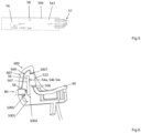
- the assembly 2 can comprise a light source subassembly 8 comprising a light source 58 arranged so that at least part of the light source faces away from the vehicle door when the grip member is attached to the external side of the vehicle door ( figure 6 ).
- the light source 58 is arranged so that the emitted light illuminates an area around the grip member 6 so that the user can reach the switch contact area 522 when the electronic switch subassembly 5 is attached to the grip member 6.
- the light source 58 is for example located under the switch contact area 522 with respect to the vehicle door ( figure 6 ), for example, when the grip member (6) is attached to the external side of the vehicle door.
- the light source 58 is arranged on the printed circuit board 566 of the electronic switch subassembly ( figure 5 ).
- the light source 58 is arranged on the first face 567 of the printed circuit board 566.
- the printed circuit board 566 presents the first electrical subcircuit 562 and the second electrical subcircuit 564 at its surface, and/or a light source 58 at its surface.
- the light source 58 can comprise or be one or several light-emitting diode(s).
- the light source 58 is arranged under the second wall 603 of the gripping part 600, for example when the grip member (6) is attached to the external side of the vehicle door.
- the light source subassembly comprises a window part 80 that is at least partially transparent, for example transparent, to the light emitted by the light source 58.
- the window part 80 is for example located under the switch contact area 522 with respect to the vehicle door.
- the window part 80 is arranged under the gripping part 600, for example under the second wall 603 of the gripping part 600 of the grip member 6, for example when the grip member (6) is attached to the external side of the vehicle door.
- the assembly 1 can comprise a housing 1001.
- the housing 1001 can comprise the electronic switch subassembly 5 and the light source subassembly 8.
- the housing 1001 can comprise an inner space 1002 dimensioned so as to receive the light source 58 of the light source subassembly 8 and the at least two switch elements 54a, 54b, 54c of the electronic switch subassembly 5.
- the inner space 1002 can be dimensioned so as to receive the printed circuit board subassembly 56, for example comprising both the light source 58 and the at least two switch elements 54a, 54b, 54c.
- Figure 6 shows the light source 58 and the switch elements 54a, 54b, 54c arranged within the inner space 1002 of the housing.
- the housing is waterproof.
- the window part 80 of the light source subassembly 8 can be arranged on the housing 1001, for example on a lower part of the housing 1001.
- the housing can comprise a first aperture 1005 configured to receive at least a part of the window part 80.
- the first aperture 1005 is arranged on a lower part of the housing 1001.
- the window part 80 can be received, at least in part, in the first aperture 1005.
- the window part 80 can be fixed to the housing 1001 by means of clipping means.
- the window part 80 can be sealed to the housing 1001 so as to form a waterproof seal.
- the switch contact area 522 of the electronic switch subassembly 5 can be arranged on the housing 1001, for example on an upper part of the housing 1001.
- the switch contact area 522 can be arranged on a part of the housing 1001 opposite to the part of the housing 1001 wherein the window part 80 is arranged.
- the housing 1001 can comprise a second aperture 1007 configured to receive at least a part of the switch contact area 522.
- the second aperture 1007 is arranged on an upper part of the housing 1001.
- the switch contact area 522 can be received, at least in part, in the second aperture 1007.
- the switch contact area 522 can be fixed to the housing 1001 by means of clipping means.
- the window part 80 can be sealed to the housing 1001 so as to form a waterproof seal.
- the housing 1001 is configured so as to be received, at least in part, within the inner space 660 of the gripping part 600 of the grip member 6.
- the housing 1001 can be received and attached to the inner space 660 of the gripping part 600 by means of clipping means.
- the housing is removably attached to the inner space 660 of the gripping part 600 of the grip member 6.
- the assembly 2 is arranged so that when the housing 1001 is received within the inner space 660 of the gripping part 600, the switch contact area 522 passes through the opening 607 of the gripping part 600 and opens on the side of the traction surface 602 of the grip member 6.
- the assembly 2 is arranged so that when the housing 1001 is received within the inner space 660 of the gripping part 600, the window part 80 is arranged under the gripping part 600, for example under the second wall 603 of the gripping part 600 of the grip member 6, for example when the grip member (6) is attached to the external side of the vehicle door.
- the electronic switch subassembly 5 can comprise electrical connection means 57 for electrically connecting the printed circuit board assembly 56 to the electrical latch.
- the electrical connection means 57 comprise one or several electrical wire(s), for example a cable surrounding the wire(s), the electrical wire(s) being provided with connections at their both ends.
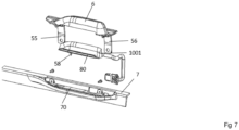
- the assembly can comprise a fixation element 7 ( figures 1 and 7 ) configured to be attached to the vehicle door 4.
- fixation element 7 is configured to be attached to an inner side of the vehicle door.
- the fixation element 7 can comprises an aperture 70 arranged in the fixation element so as to receive at least a part the grip member 6 and the housing 1001.
- the aperture 70 opens to the external side 44 of the vehicle door when the fixation element is attached to the inner side of the vehicle door.
- a vehicle door 4 is described.
- the vehicle door 4 comprises the assembly 2 for opening and/or closing a vehicle door hereabove and a belt line 46 from which can extend a window glass 48 ( figure 2 ).
- the beltline 46 is a line representing the bottom edge of a vehicle's glass panels.
- the grip member 6, to which the electronic switch subassembly 5 is attached, is for example arranged at the belt line 46, for example between a window glass 48 and an end portion 49 of the vehicle door 4.
- end portion of the vehicle door » means a portion comprising an edge of the vehicle door, a free end 49' of the vehicle door.
- a method for opening a vehicle door 4 by means of the assembly 2 comprises the activation of the at least one electronic switch subassembly 5 by a user's touch so as to send a signal to an electronic latch to open the door 4.
- the activation of the at least one electronic switch subassembly 5 comprises, in response to a user's touch on the switch contact area 522, a step of activation of at least one of the switches 542a, 542b, 542c, 544a, 544b, 544c, for instance as described hereabove.
- the signal to an electronic latch to open the door 4 can also comprise a signal to unlock the door 4.
- a method for obtaining the subassembly 5 is described.
- the method comprises assembling the switch contact area 522 and the printed circuit board assembly 56.
- a method for mounting the assembly on a vehicle door is described.
- the method comprises assembling the electronic switch subassembly 5 to the grip member 6.
- the method can comprise inserting at least a part of the housing 1001 within the inner space 660 of the gripping part 600 and fixing the housing 1001 to the gripping part 600.
- the housing 1001 can be inserted into the inner space 660 of the gripping part 600 from a lower side of the grip member 6.
- the method comprises arranging at least a part of the assembled housing 1001 and grip member 6 in the aperture 70 of the fixation element 7.
- the method comprises attaching the fixation element 7 to the vehicle door 4.
- the housing 1001 can be inserted into the grip member 6 and attached to the grip member 6, for example by means of clipping means, and then attached to the fixation element 7.
- the assembly can fit also other functions like a courtesy light module and comprises for example a light module configured to project a light form on the ground, for example a symbol, for example a logo.
Landscapes
- Engineering & Computer Science (AREA)
- Mechanical Engineering (AREA)
- Lock And Its Accessories (AREA)
Priority Applications (3)
| Application Number | Priority Date | Filing Date | Title |
|---|---|---|---|
| EP22214720.9A EP4390019A1 (de) | 2022-12-19 | 2022-12-19 | Anordnung zum öffnen und/oder schliessen einer fahrzeugtür |
| US18/523,505 US20240200370A1 (en) | 2022-12-19 | 2023-11-29 | Assembly for opening and/or closing a vehicle door |
| CN202311748742.8A CN118223747A (zh) | 2022-12-19 | 2023-12-18 | 用于打开和/或关闭车门的组件 |
Applications Claiming Priority (1)
| Application Number | Priority Date | Filing Date | Title |
|---|---|---|---|
| EP22214720.9A EP4390019A1 (de) | 2022-12-19 | 2022-12-19 | Anordnung zum öffnen und/oder schliessen einer fahrzeugtür |
Publications (1)
| Publication Number | Publication Date |
|---|---|
| EP4390019A1 true EP4390019A1 (de) | 2024-06-26 |
Family
ID=84541508
Family Applications (1)
| Application Number | Title | Priority Date | Filing Date |
|---|---|---|---|
| EP22214720.9A Pending EP4390019A1 (de) | 2022-12-19 | 2022-12-19 | Anordnung zum öffnen und/oder schliessen einer fahrzeugtür |
Country Status (3)
| Country | Link |
|---|---|
| US (1) | US20240200370A1 (de) |
| EP (1) | EP4390019A1 (de) |
| CN (1) | CN118223747A (de) |
Cited By (1)
| Publication number | Priority date | Publication date | Assignee | Title |
|---|---|---|---|---|
| EP4726150A1 (de) * | 2024-10-11 | 2026-04-15 | HUF Hülsbeck & Fürst GmbH & Co. KG | Fahrzeugtürgriff |
Families Citing this family (2)
| Publication number | Priority date | Publication date | Assignee | Title |
|---|---|---|---|---|
| EP4209391A1 (de) * | 2022-01-11 | 2023-07-12 | U-Shin Italia S.p.A. | Elektronische schalterunterbaugruppe zur montage an einer innenseite einer fahrzeugtür |
| US12428882B2 (en) | 2022-12-02 | 2025-09-30 | Ford Global Technologies, Llc | Door assembly for motor vehicle |
Citations (6)
| Publication number | Priority date | Publication date | Assignee | Title |
|---|---|---|---|---|
| JPH0735707B2 (ja) * | 1987-07-13 | 1995-04-19 | 株式会社大井製作所 | 上下開閉式車両用ドアの開閉装置 |
| US20110058386A1 (en) * | 2009-09-08 | 2011-03-10 | Olsa S.P.A. | Integrated element for the illumination of a number plate and for the opening of a door of a vehicle |
| DE102015119224A1 (de) * | 2015-11-09 | 2017-05-11 | Osram Oled Gmbh | Öffnungsvorrichtung zum Freigeben eines Zugangs, Kraftfahrzeug und Verfahren zum Freigeben eines Zugangs |
| US20190093411A1 (en) * | 2017-09-26 | 2019-03-28 | Toyoda Gosel Co., Ltd. | Rear door open/close switch |
| FR3096713A1 (fr) * | 2019-05-29 | 2020-12-04 | Renault S.A.S. | Commande d’ouverture d’une porte de véhicule. |
| US20220213722A1 (en) * | 2021-01-07 | 2022-07-07 | Ford Global Technologies, Llc | Door assembly for motor vehicle |
Family Cites Families (14)
| Publication number | Priority date | Publication date | Assignee | Title |
|---|---|---|---|---|
| ATE333552T1 (de) * | 2003-11-21 | 2006-08-15 | Huf Huelsbeck & Fuerst Gmbh | Baueinheit bestehend aus einer handhabe und wenigstens einer funktionseinheit |
| US9156335B1 (en) * | 2014-06-12 | 2015-10-13 | Ford Global Technologies, Llc | Structural door handle attached to door structure at the door window belt |
| DE102017002041A1 (de) * | 2017-03-02 | 2018-09-06 | Leopold Kostal Gmbh & Co. Kg | Bedienelement |
| KR102406058B1 (ko) * | 2017-10-12 | 2022-06-08 | 현대자동차주식회사 | 차량의 부품통합형 테일게이트 핸들스위치 |
| JP7052619B2 (ja) * | 2018-07-30 | 2022-04-12 | 豊田合成株式会社 | バックドアハンドル装置及びその製造方法 |
| DE102019113130A1 (de) * | 2019-05-17 | 2020-11-19 | Witte Automotive Gmbh | Türgriffanordnung |
| US11554646B2 (en) * | 2019-05-23 | 2023-01-17 | Ford Global Technologies, Llc | Open loop fixed outside pull handle integrated with door belt seal |
| US11619079B2 (en) * | 2019-12-09 | 2023-04-04 | Ford Global Technologies, Llc | Vehicle powered closure handle assembly and powered closure actuating method |
| EP3868987B8 (de) * | 2020-02-20 | 2024-05-29 | Minebea AccessSolutions Deutschland GmbH | Fahrzeugtürgriff mit mehreren schalteinheiten |
| ES2982983T3 (es) * | 2021-06-24 | 2024-10-21 | Minebea Accesssolutions France | Conjunto de manija de puerta de vehículo |
| DE102021214163A1 (de) * | 2021-12-10 | 2023-06-15 | Witte Automotive Gmbh | Fahrzeugtür mit einer Griffanordnung und Fahrzeug |
| DE102022127594A1 (de) * | 2022-10-19 | 2024-04-25 | Bayerische Motoren Werke Aktiengesellschaft | Flügelelement, insbesondere Fahrzeugtür, für ein Fahrzeug sowie Fahrzeug |
| EP4461912B1 (de) * | 2023-05-09 | 2025-10-15 | Minebea AccessSolutions Italia S.p.A. | Durch einen dehnungsmessstreifensensor gesteuerter kraftfahrzeugaussengriff |
| EP4549686A1 (de) * | 2023-10-30 | 2025-05-07 | Minebea AccessSolutions Italia S.p.A. | Türaufbau für ein kraftfahrzeug |
-
2022
- 2022-12-19 EP EP22214720.9A patent/EP4390019A1/de active Pending
-
2023
- 2023-11-29 US US18/523,505 patent/US20240200370A1/en active Pending
- 2023-12-18 CN CN202311748742.8A patent/CN118223747A/zh active Pending
Patent Citations (6)
| Publication number | Priority date | Publication date | Assignee | Title |
|---|---|---|---|---|
| JPH0735707B2 (ja) * | 1987-07-13 | 1995-04-19 | 株式会社大井製作所 | 上下開閉式車両用ドアの開閉装置 |
| US20110058386A1 (en) * | 2009-09-08 | 2011-03-10 | Olsa S.P.A. | Integrated element for the illumination of a number plate and for the opening of a door of a vehicle |
| DE102015119224A1 (de) * | 2015-11-09 | 2017-05-11 | Osram Oled Gmbh | Öffnungsvorrichtung zum Freigeben eines Zugangs, Kraftfahrzeug und Verfahren zum Freigeben eines Zugangs |
| US20190093411A1 (en) * | 2017-09-26 | 2019-03-28 | Toyoda Gosel Co., Ltd. | Rear door open/close switch |
| FR3096713A1 (fr) * | 2019-05-29 | 2020-12-04 | Renault S.A.S. | Commande d’ouverture d’une porte de véhicule. |
| US20220213722A1 (en) * | 2021-01-07 | 2022-07-07 | Ford Global Technologies, Llc | Door assembly for motor vehicle |
Cited By (1)
| Publication number | Priority date | Publication date | Assignee | Title |
|---|---|---|---|---|
| EP4726150A1 (de) * | 2024-10-11 | 2026-04-15 | HUF Hülsbeck & Fürst GmbH & Co. KG | Fahrzeugtürgriff |
Also Published As
| Publication number | Publication date |
|---|---|
| CN118223747A (zh) | 2024-06-21 |
| US20240200370A1 (en) | 2024-06-20 |
Similar Documents
| Publication | Publication Date | Title |
|---|---|---|
| EP4390019A1 (de) | Anordnung zum öffnen und/oder schliessen einer fahrzeugtür | |
| JP3619505B2 (ja) | 車両用ドアのハンドル装置 | |
| US6218933B1 (en) | Security system for a motor vehicle opening leaf | |
| US10253530B2 (en) | Vehicle unlocking control device provided with an outer control member having an over-molded mounting | |
| US6693552B1 (en) | Hand-held control device | |
| US7931314B2 (en) | Vehicle door outer handle system | |
| CN101123143B (zh) | 锁定解除操作装置 | |
| US11692378B2 (en) | External handle device for vehicle doors | |
| CN114450184A (zh) | 充电或燃料补给凹口 | |
| JP5064055B2 (ja) | 車両用ドアのアウトハンドル装置 | |
| EP4390020A1 (de) | Anordnung zum öffnen und/oder schliessen einer fahrzeugtür | |
| EP4106503A1 (de) | Elektronische steuerungsvorrichtung | |
| CN105128759B (zh) | 门窗开闭开关组件 | |
| US10132652B2 (en) | Electrostatic sensor | |
| US20210156174A1 (en) | Motor vehicle door handle arrangment with an emergency actuating lever | |
| JP2004169427A (ja) | 車両用ドアハンドル装置 | |
| EP4209391A1 (de) | Elektronische schalterunterbaugruppe zur montage an einer innenseite einer fahrzeugtür | |
| CN1708330A (zh) | 电击去纤颤器 | |
| JP3668566B2 (ja) | 操作盤の電気接続構造 | |
| JP4169901B2 (ja) | 電子符号錠用キー | |
| CN221125773U (zh) | 开关总成、车门总成、车辆 | |
| JPH0747768Y2 (ja) | 照明式押釦構造 | |
| US12514404B2 (en) | Blender | |
| JP4119337B2 (ja) | 車両用ドアのアウトハンドル装置 | |
| JP2006090032A (ja) | 自動開扉装置のスイッチ装置及びスイッチモジュール |
Legal Events
| Date | Code | Title | Description |
|---|---|---|---|
| PUAI | Public reference made under article 153(3) epc to a published international application that has entered the european phase |
Free format text: ORIGINAL CODE: 0009012 |
|
| STAA | Information on the status of an ep patent application or granted ep patent |
Free format text: STATUS: REQUEST FOR EXAMINATION WAS MADE |
|
| 17P | Request for examination filed |
Effective date: 20221219 |
|
| AK | Designated contracting states |
Kind code of ref document: A1 Designated state(s): AL AT BE BG CH CY CZ DE DK EE ES FI FR GB GR HR HU IE IS IT LI LT LU LV MC ME MK MT NL NO PL PT RO RS SE SI SK SM TR |