EP4390048A1 - Cadre pour un dispositif de protection - Google Patents
Cadre pour un dispositif de protection Download PDFInfo
- Publication number
- EP4390048A1 EP4390048A1 EP22214854.6A EP22214854A EP4390048A1 EP 4390048 A1 EP4390048 A1 EP 4390048A1 EP 22214854 A EP22214854 A EP 22214854A EP 4390048 A1 EP4390048 A1 EP 4390048A1
- Authority
- EP
- European Patent Office
- Prior art keywords
- profile strip
- frame
- inner profile
- outer profile
- struts
- Prior art date
- Legal status (The legal status is an assumption and is not a legal conclusion. Google has not performed a legal analysis and makes no representation as to the accuracy of the status listed.)
- Pending
Links
Images

Classifications
-
- E—FIXED CONSTRUCTIONS
- E06—DOORS, WINDOWS, SHUTTERS, OR ROLLER BLINDS IN GENERAL; LADDERS
- E06B—FIXED OR MOVABLE CLOSURES FOR OPENINGS IN BUILDINGS, VEHICLES, FENCES OR LIKE ENCLOSURES IN GENERAL, e.g. DOORS, WINDOWS, BLINDS, GATES
- E06B9/00—Screening or protective devices for wall or similar openings, with or without operating or securing mechanisms; Closures of similar construction
- E06B9/52—Devices affording protection against insects, e.g. fly screens; Mesh windows for other purposes
Definitions
- the present invention relates to a frame for a protective device and in particular to a frame for an insect, pollen and/or sun protection device.
- Such a frame usually has four frame struts that are arranged at right angles to each other and enclose a frame opening.
- a protective fabric can be attached to the frame, which prevents pollen and/or insects from passing through the frame opening. At the same time, it can also provide sun protection.
- the frame struts can have projections and/or recesses extending in the longitudinal direction of the frame struts, to which the fabric can be attached using suitable fastening elements (such as piping strips or profile strips).
- the fabric can also be pleated. so that the fabric can be moved in the frame between a position closing the frame opening and an opening position.
- the frame can be dimensioned in such a way that a protective device is formed for a window.
- fastening means are provided with which the frame can be attached to a window frame, for example.
- hanging brackets can be provided which are attached to the frame and with which the frame is hung on the window frame.
- the frame can also be dimensioned in such a way that it serves as a protective device for a door.
- the frame is attached to a door frame, for example, using hinges, so that the frame itself forms a type of door with which the door opening can be closed.
- a frame for a door usually has a central strut that connects the frame struts that are arranged vertically when assembled, for example, and is itself arranged horizontally and parallel to the two upper and lower horizontal frame struts.
- a frame strut comprises an outer profile strip and an inner profile strip that can be moved telescopically relative to one another.
- the inner profile strip which is partially arranged in the outer profile strip, protrudes over the outer profile strip in sections.
- the frame struts do not have to be shortened by an end user in order to a window or a door. Since in such telescopic frames each frame strut has a kind of step in the area where the inner profile strip exits the outer profile strip, the visual impression is influenced by this.
- the object of the present invention is therefore to at least partially eliminate the disadvantages described with reference to the prior art and in particular to provide a frame with a high level of stability in an alternative manner.
- a frame for a protective device which comprises at least four frame struts, preferably arranged at right angles to one another, wherein at least one of the four frame struts has an outer profile strip and at least one inner profile strip, wherein the at least one inner profile strip is arranged and fixed completely within the outer profile strip.
- the basic idea of the present invention is that at least one of the frame struts comprises an inner profile strip which is arranged completely within an outer profile strip of the frame strut, so that only the outer profile strip is visible from the outside.
- the inner profile strip is fixed in its position within the outer profile strip, so that the inner profile strip cannot move relative to the outer profile strip. Since at least one frame strut has both an outer profile strip and an inner profile strip, at least in sections, the stability of the frame is increased.
- the inner circumference design of the outer profile strip corresponds to the outer circumference design of the inner profile strip. So, for example, if the outer circumference design of the inner profile strip is rectangular, the inner circumference design of the outer profile strip is also rectangular, whereby these are dimensioned in such a way that the inner profile strip can be pushed into the outer profile strip for assembly, but otherwise there is hardly any play.
- the circumference design of the profile strips is not exactly rectangular, but that the profile strips form corresponding projections and recesses in the cross-section, which further increases stability.
- an inner profile strip can extend over the entire length of the outer profile strip, so that the inner profile strip and the outer profile strip have almost the same length.
- two or more inner profile strips can be arranged within an outer profile strip of a frame strut.
- the inner profile strips are therefore arranged at a distance from one another within the one outer profile strip and fixed in the outer profile strip.
- the inner profile strips can thus be attached to the Positions on an outer profile strip of a frame strut where the outer profile strip must be supported to increase stability.
- the frame can be designed for a protective device for a door, in which case only the frame strut to which a hinge is attached has at least one profile strip within the outer profile strip.
- a hinge band of the hinge can be attached to both the outer profile strip and the inner profile strip of the frame strut, for example by a screw passing through both the outer profile strip and the inner profile strip. This increases the stability of the frame in the area where the hinges are attached.
- two or more or in particular all frame struts each have an outer profile strip and at least one inner profile strip.
- the frame is preferably reinforced in the area of its corners, in which two frame struts are connected to one another.
- at least two adjacent frame struts each have an outer profile strip and at least one inner profile strip, with two inner profile strips of adjacent frame struts being connected to one another by means of a corner connector.
- the corner connector preferably has two legs, each of which is inserted into an inner profile strip.
- the legs of the corner connector are arranged in particular at a right angle to one another, with an outer profile of the legs being adapted to an inner profile of the inner profile strip, so that the legs can be inserted into the inner profile strips with only a small amount of play. can be.
- the legs can also be dimensioned in such a way that the corner connectors can be inserted into the inner profile strips in a force-fitting manner.
- two inner profile strips of adjacent frame struts are first connected to one another using a corner connector.
- the corner connectors can be fixed in the inner profile strips in a suitable manner.
- the corner connectors can be glued to the inner profile strips.
- the leg of the corner connector is connected to the associated inner profile strip by pressing.
- the inner profile strip and/or the leg of the corner connector is plastically deformed.
- the corner connector can have recesses into which the inner profile strip is pressed during deformation.
- the inner profile strips of adjacent frame struts are beveled at their mutually facing ends.
- the corresponding profile strip is cut at a 45° angle to its direction of extension, so that adjacent profile strips can be beveled at a corner of the frame and lie against each other.
- all frame struts of the frame have an identical profile outer profile strip and that adjacent outer profile strips abut one another with a miter cut.
- Such a frame has in particular exactly four frame struts, which have miter cuts at both ends of the outer profile strips, so that an outer profile cross-section that is constant in the circumferential direction is provided.
- the at least one inner profile strip can be fixed in the outer profile strip in a form-fitting and/or force-fitting manner, for example by gluing, welding or other suitable means.
- the at least one inner profile strip is fixed in the outer profile strip by plastic deformation of the outer profile strip and/or the inner profile strip.
- the inner profile strip can first be pushed into the outer profile strip and the inner profile strip can then be fixed by pressing it onto the outer profile strip.
- the inner profile strip, the outer profile strip and the legs of the corner connector are pressed together at the same time (i.e. in one processing step).
- two inner profile strips are first connected to each other via a corner connector for each corner, with the inner profile strips then being pushed into the corresponding outer profile strips.
- the inner profile strips are first fixed to the legs of the corner connectors and only after the inner profile strips have been pushed into the outer profile strips is the inner profile strip connected to the outer profile strip.
- the legs of the corner connectors are pushed into the inner profile strip and after the inner profile strip has been pushed into the outer profile strip, the inner profile strip is fixed to both the outer profile strip and the leg in one processing step by deformation.
- the frame when the frame is used as part of a protective device for a door, the frame comprises a central strut which connects two frame struts to each other and is arranged parallel to the two other frame struts.
- the central strut which connects two frame struts to each other and is arranged parallel to the two other frame struts.
- at least one of the frame struts connected to one another by the central strut has an inner profile strip fixed within an outer profile strip in the area of the connection to the central strut.
- the frame strut which is vertically aligned when the door is installed, therefore has an inner profile strip inside the outer profile strip in the area in which it is connected to the central strut.
- both frame struts which are vertically aligned when installed have an inner profile strip.
- a screw for attaching the central strut passes through both the outer profile strip and the inner profile strip.
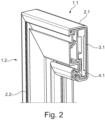
- the figures show a section of a frame that includes four frame struts.
- Two frame struts 1.1 and 1.2 are shown, which are connected to each other by means of a corner connector 4 to form a corner of the frame.
- the first frame strut 1.1 comprises an outer profile strip 2.1 and an inner profile strip 3.1.
- the second frame strut 1.2 comprises an outer profile strip 2.2 and an inner profile strip 3.2.
- the corner connector 4 has a Figure 1 visible first leg 4.1, which is inserted into the inner profile strip 3.1 of the first frame strut 1.1 when assembled.
- the corner connector 4 also has a second leg 4.2, which is When assembled, it is inserted into the inner profile strip 3.2 of the second frame strut 1.2.
- the inner profile strips 3.1 and 3.2 are each arranged completely in the corresponding outer profile strip 2.1 and 2.2, whereby the inner profile strips 3.1 and 3.2 are arranged immovably relative to the outer profile strips 2.1 and 2.2.
- the inner profile strips 3.1 and 3.2 can be pressed together with the respective outer profile strip 2.1 and 2.2, for example by suitable measures.
- the inner profile strips 3.1 and 3.2 can be pressed together with the corresponding leg 4.1 of the corner connector 4, so that the profile strips are captively connected to the corner connector 4.
- the inner profile strips 3.1 and 3.2 When assembled, the inner profile strips 3.1 and 3.2 are not visible from the outside, as they are arranged completely in the outer profile strips 2.1 and 2.2. Since the inner profile strips 3.1 and 3.2 extend at least in sections along the outer profile strips 2.1 and 2.2 of the frame struts 1.1 and 1.2, the frame struts 1.2 and 2.2 have increased stability. In principle, an inner profile strip 3.1 can extend over the entire length of an outer profile strip 2.1. However, it is also possible for several inner profile strips 3.1 to be arranged within an outer profile strip 2.1, particularly in the corner areas of the frame.
- the profile strips 2.1, 2.2, 3.1, and 3.2 each have a mitre cut, which ensures that the profile strips fit together in the corner area when assembled.
Landscapes
- Engineering & Computer Science (AREA)
- Structural Engineering (AREA)
- Life Sciences & Earth Sciences (AREA)
- Insects & Arthropods (AREA)
- Pest Control & Pesticides (AREA)
- Architecture (AREA)
- Civil Engineering (AREA)
- Door And Window Frames Mounted To Openings (AREA)
Priority Applications (1)
| Application Number | Priority Date | Filing Date | Title |
|---|---|---|---|
| EP22214854.6A EP4390048A1 (fr) | 2022-12-20 | 2022-12-20 | Cadre pour un dispositif de protection |
Applications Claiming Priority (1)
| Application Number | Priority Date | Filing Date | Title |
|---|---|---|---|
| EP22214854.6A EP4390048A1 (fr) | 2022-12-20 | 2022-12-20 | Cadre pour un dispositif de protection |
Publications (1)
| Publication Number | Publication Date |
|---|---|
| EP4390048A1 true EP4390048A1 (fr) | 2024-06-26 |
Family
ID=84541406
Family Applications (1)
| Application Number | Title | Priority Date | Filing Date |
|---|---|---|---|
| EP22214854.6A Pending EP4390048A1 (fr) | 2022-12-20 | 2022-12-20 | Cadre pour un dispositif de protection |
Country Status (1)
| Country | Link |
|---|---|
| EP (1) | EP4390048A1 (fr) |
Citations (5)
| Publication number | Priority date | Publication date | Assignee | Title |
|---|---|---|---|---|
| KR200437856Y1 (ko) * | 2007-02-28 | 2008-01-02 | 대현산업 (주) | 방충문이 구비된 이중문 |
| KR20140020519A (ko) * | 2012-08-09 | 2014-02-19 | 강민성 | 이탈방지용 방충망장치 |
| KR20150002067U (ko) * | 2013-11-22 | 2015-06-01 | 이지연 | 방범 기능을 갖는 안전 방충 프레임 |
| KR101628714B1 (ko) * | 2015-11-18 | 2016-06-09 | 해피창 주식회사 | 방충망 고정프레임 |
| KR101825824B1 (ko) * | 2016-07-29 | 2018-02-05 | 이지연 | 방범 방충망용 프로파일 |
-
2022
- 2022-12-20 EP EP22214854.6A patent/EP4390048A1/fr active Pending
Patent Citations (5)
| Publication number | Priority date | Publication date | Assignee | Title |
|---|---|---|---|---|
| KR200437856Y1 (ko) * | 2007-02-28 | 2008-01-02 | 대현산업 (주) | 방충문이 구비된 이중문 |
| KR20140020519A (ko) * | 2012-08-09 | 2014-02-19 | 강민성 | 이탈방지용 방충망장치 |
| KR20150002067U (ko) * | 2013-11-22 | 2015-06-01 | 이지연 | 방범 기능을 갖는 안전 방충 프레임 |
| KR101628714B1 (ko) * | 2015-11-18 | 2016-06-09 | 해피창 주식회사 | 방충망 고정프레임 |
| KR101825824B1 (ko) * | 2016-07-29 | 2018-02-05 | 이지연 | 방범 방충망용 프로파일 |
Similar Documents
| Publication | Publication Date | Title |
|---|---|---|
| EP0789984A1 (fr) | Baie pour armoire de distribution | |
| EP3680430B1 (fr) | Porte de bâtiment | |
| AT523544B1 (de) | Kunststoff-Metall-Fenstersystem | |
| EP3835539B1 (fr) | Kit pour un cadre | |
| EP3690177A1 (fr) | Raccord profilé à articulation rotative | |
| DE4216260C2 (de) | Gebäudefenster | |
| DE102020100493A1 (de) | Torpfosten für Sichtschutz | |
| DE102014119021A1 (de) | Anordnung zum Befestigen eines Pfostens aus Kunststoff an einer Rahmenleiste eines Fensters oder einer Türe mittels eines Pfostenverbinders | |
| DE102015116588B4 (de) | Bausatz für einen Spannrahmen | |
| EP1229620A1 (fr) | Procédé d'assemblage d'une armoire électrique et armoire électrique | |
| EP4390048A1 (fr) | Cadre pour un dispositif de protection | |
| DE3706315A1 (de) | Schrank | |
| EP3276116B1 (fr) | Agencement de fenêtre avec un dispositif de protection contre le soleil | |
| DE2923903A1 (de) | Wandbefestigungselement fuer plattenheizkoerper | |
| EP4202174A2 (fr) | Kit de construction pour cadre et connecteur de profilé pour un cadre | |
| DE10133077A1 (de) | Insektenschutzgitter | |
| DE4321466A1 (de) | Zarge für ein Fenster | |
| EP1336718B1 (fr) | Moustiquaire pour une fenêtre ou une porte | |
| EP3623568A1 (fr) | Cadre d'un dispositif de protection | |
| EP0342662A1 (fr) | Dispositif pour assembler des éléments de grilles décoratives | |
| DE102006062161A1 (de) | Kunststoff-Profilsystem für ein Fenster oder eine Tür | |
| EP0715051A1 (fr) | Fixation de vitrages doubles ou multiples pour la fermeture d'ouvertures de bâtiment | |
| DE10322029B4 (de) | Profilsystem | |
| EP4722484A2 (fr) | Rail profilé doté d'une pièce de préhension | |
| AT316829B (de) | Metallrahmen |
Legal Events
| Date | Code | Title | Description |
|---|---|---|---|
| PUAI | Public reference made under article 153(3) epc to a published international application that has entered the european phase |
Free format text: ORIGINAL CODE: 0009012 |
|
| STAA | Information on the status of an ep patent application or granted ep patent |
Free format text: STATUS: THE APPLICATION HAS BEEN PUBLISHED |
|
| AK | Designated contracting states |
Kind code of ref document: A1 Designated state(s): AL AT BE BG CH CY CZ DE DK EE ES FI FR GB GR HR HU IE IS IT LI LT LU LV MC ME MK MT NL NO PL PT RO RS SE SI SK SM TR |
|
| STAA | Information on the status of an ep patent application or granted ep patent |
Free format text: STATUS: REQUEST FOR EXAMINATION WAS MADE |
|
| 17P | Request for examination filed |
Effective date: 20240919 |
|
| RBV | Designated contracting states (corrected) |
Designated state(s): AL AT BE BG CH CY CZ DE DK EE ES FI FR GB GR HR HU IE IS IT LI LT LU LV MC ME MK MT NL NO PL PT RO RS SE SI SK SM TR |
|
| RAP1 | Party data changed (applicant data changed or rights of an application transferred) |
Owner name: BASH-TEC GMBH |
|
| RIN1 | Information on inventor provided before grant (corrected) |
Inventor name: BASH-TEC GMBH |
|
| RIN1 | Information on inventor provided before grant (corrected) |
Inventor name: BUEDENBENDER ARND |
|
| GRAP | Despatch of communication of intention to grant a patent |
Free format text: ORIGINAL CODE: EPIDOSNIGR1 |
|
| STAA | Information on the status of an ep patent application or granted ep patent |
Free format text: STATUS: GRANT OF PATENT IS INTENDED |
|
| RIC1 | Information provided on ipc code assigned before grant |
Ipc: E06B 9/52 20060101AFI20260323BHEP |