EP4390063A1 - Conduit d'échappement pour centrale électrique d'aéronef hybride - Google Patents
Conduit d'échappement pour centrale électrique d'aéronef hybride Download PDFInfo
- Publication number
- EP4390063A1 EP4390063A1 EP23219440.7A EP23219440A EP4390063A1 EP 4390063 A1 EP4390063 A1 EP 4390063A1 EP 23219440 A EP23219440 A EP 23219440A EP 4390063 A1 EP4390063 A1 EP 4390063A1
- Authority
- EP
- European Patent Office
- Prior art keywords
- electric machine
- exhaust duct
- section
- rotor
- degrees
- Prior art date
- Legal status (The legal status is an assumption and is not a legal conclusion. Google has not performed a legal analysis and makes no representation as to the accuracy of the status listed.)
- Pending
Links
Images




Classifications
-
- B—PERFORMING OPERATIONS; TRANSPORTING
- B64—AIRCRAFT; AVIATION; COSMONAUTICS
- B64D—EQUIPMENT FOR FITTING IN OR TO AIRCRAFT; FLIGHT SUITS; PARACHUTES; ARRANGEMENT OR MOUNTING OF POWER PLANTS OR PROPULSION TRANSMISSIONS IN AIRCRAFT
- B64D27/00—Arrangement or mounting of power plants in aircraft; Aircraft characterised by the type or position of power plants
- B64D27/02—Aircraft characterised by the type or position of power plants
- B64D27/10—Aircraft characterised by the type or position of power plants of gas-turbine type
-
- B—PERFORMING OPERATIONS; TRANSPORTING
- B64—AIRCRAFT; AVIATION; COSMONAUTICS
- B64D—EQUIPMENT FOR FITTING IN OR TO AIRCRAFT; FLIGHT SUITS; PARACHUTES; ARRANGEMENT OR MOUNTING OF POWER PLANTS OR PROPULSION TRANSMISSIONS IN AIRCRAFT
- B64D27/00—Arrangement or mounting of power plants in aircraft; Aircraft characterised by the type or position of power plants
- B64D27/02—Aircraft characterised by the type or position of power plants
- B64D27/24—Aircraft characterised by the type or position of power plants using steam or spring force
-
- B—PERFORMING OPERATIONS; TRANSPORTING
- B64—AIRCRAFT; AVIATION; COSMONAUTICS
- B64D—EQUIPMENT FOR FITTING IN OR TO AIRCRAFT; FLIGHT SUITS; PARACHUTES; ARRANGEMENT OR MOUNTING OF POWER PLANTS OR PROPULSION TRANSMISSIONS IN AIRCRAFT
- B64D33/00—Arrangement in aircraft of power plant parts or auxiliaries not otherwise provided for
- B64D33/04—Arrangement in aircraft of power plant parts or auxiliaries not otherwise provided for of exhaust outlets or jet pipes
-
- B—PERFORMING OPERATIONS; TRANSPORTING
- B64—AIRCRAFT; AVIATION; COSMONAUTICS
- B64D—EQUIPMENT FOR FITTING IN OR TO AIRCRAFT; FLIGHT SUITS; PARACHUTES; ARRANGEMENT OR MOUNTING OF POWER PLANTS OR PROPULSION TRANSMISSIONS IN AIRCRAFT
- B64D35/00—Transmitting power from power plants to propellers or rotors; Arrangements of transmissions
- B64D35/02—Transmitting power from power plants to propellers or rotors; Arrangements of transmissions specially adapted for specific power plants
- B64D35/021—Transmitting power from power plants to propellers or rotors; Arrangements of transmissions specially adapted for specific power plants for electric power plants
- B64D35/022—Transmitting power from power plants to propellers or rotors; Arrangements of transmissions specially adapted for specific power plants for electric power plants of hybrid-electric type
- B64D35/024—Transmitting power from power plants to propellers or rotors; Arrangements of transmissions specially adapted for specific power plants for electric power plants of hybrid-electric type of series type
-
- B—PERFORMING OPERATIONS; TRANSPORTING
- B64—AIRCRAFT; AVIATION; COSMONAUTICS
- B64D—EQUIPMENT FOR FITTING IN OR TO AIRCRAFT; FLIGHT SUITS; PARACHUTES; ARRANGEMENT OR MOUNTING OF POWER PLANTS OR PROPULSION TRANSMISSIONS IN AIRCRAFT
- B64D35/00—Transmitting power from power plants to propellers or rotors; Arrangements of transmissions
- B64D35/08—Transmitting power from power plants to propellers or rotors; Arrangements of transmissions characterised by the transmission being driven by a plurality of power plants
-
- F—MECHANICAL ENGINEERING; LIGHTING; HEATING; WEAPONS; BLASTING
- F01—MACHINES OR ENGINES IN GENERAL; ENGINE PLANTS IN GENERAL; STEAM ENGINES
- F01D—NON-POSITIVE DISPLACEMENT MACHINES OR ENGINES, e.g. STEAM TURBINES
- F01D15/00—Adaptations of machines or engines for special use; Combinations of engines with devices driven thereby
- F01D15/10—Adaptations for driving, or combinations with, electric generators
-
- F—MECHANICAL ENGINEERING; LIGHTING; HEATING; WEAPONS; BLASTING
- F02—COMBUSTION ENGINES; HOT-GAS OR COMBUSTION-PRODUCT ENGINE PLANTS
- F02C—GAS-TURBINE PLANTS; AIR INTAKES FOR JET-PROPULSION PLANTS; CONTROLLING FUEL SUPPLY IN AIR-BREATHING JET-PROPULSION PLANTS
- F02C3/00—Gas-turbine plants characterised by the use of combustion products as the working fluid
- F02C3/04—Gas-turbine plants characterised by the use of combustion products as the working fluid having a turbine driving a compressor
-
- F—MECHANICAL ENGINEERING; LIGHTING; HEATING; WEAPONS; BLASTING
- F02—COMBUSTION ENGINES; HOT-GAS OR COMBUSTION-PRODUCT ENGINE PLANTS
- F02C—GAS-TURBINE PLANTS; AIR INTAKES FOR JET-PROPULSION PLANTS; CONTROLLING FUEL SUPPLY IN AIR-BREATHING JET-PROPULSION PLANTS
- F02C6/00—Plural gas-turbine plants; Combinations of gas-turbine plants with other apparatus; Adaptations of gas-turbine plants for special use
-
- F—MECHANICAL ENGINEERING; LIGHTING; HEATING; WEAPONS; BLASTING
- F02—COMBUSTION ENGINES; HOT-GAS OR COMBUSTION-PRODUCT ENGINE PLANTS
- F02C—GAS-TURBINE PLANTS; AIR INTAKES FOR JET-PROPULSION PLANTS; CONTROLLING FUEL SUPPLY IN AIR-BREATHING JET-PROPULSION PLANTS
- F02C6/00—Plural gas-turbine plants; Combinations of gas-turbine plants with other apparatus; Adaptations of gas-turbine plants for special use
- F02C6/20—Adaptations of gas-turbine plants for driving vehicles
- F02C6/206—Adaptations of gas-turbine plants for driving vehicles the vehicles being airscrew driven
-
- F—MECHANICAL ENGINEERING; LIGHTING; HEATING; WEAPONS; BLASTING
- F02—COMBUSTION ENGINES; HOT-GAS OR COMBUSTION-PRODUCT ENGINE PLANTS
- F02C—GAS-TURBINE PLANTS; AIR INTAKES FOR JET-PROPULSION PLANTS; CONTROLLING FUEL SUPPLY IN AIR-BREATHING JET-PROPULSION PLANTS
- F02C7/00—Features, components parts, details or accessories, not provided for in, or of interest apart form groups F02C1/00 - F02C6/00; Air intakes for jet-propulsion plants
- F02C7/36—Power transmission arrangements between the different shafts of the gas turbine plant, or between the gas-turbine plant and the power user
-
- F—MECHANICAL ENGINEERING; LIGHTING; HEATING; WEAPONS; BLASTING
- F02—COMBUSTION ENGINES; HOT-GAS OR COMBUSTION-PRODUCT ENGINE PLANTS
- F02K—JET-PROPULSION PLANTS
- F02K1/00—Plants characterised by the form or arrangement of the jet pipe or nozzle; Jet pipes or nozzles peculiar thereto
- F02K1/40—Nozzles having means for dividing the jet into a plurality of partial jets or having an elongated cross-section outlet
-
- F—MECHANICAL ENGINEERING; LIGHTING; HEATING; WEAPONS; BLASTING
- F02—COMBUSTION ENGINES; HOT-GAS OR COMBUSTION-PRODUCT ENGINE PLANTS
- F02K—JET-PROPULSION PLANTS
- F02K1/00—Plants characterised by the form or arrangement of the jet pipe or nozzle; Jet pipes or nozzles peculiar thereto
- F02K1/52—Nozzles specially constructed for positioning adjacent to another nozzle or to a fixed member, e.g. fairing
-
- F—MECHANICAL ENGINEERING; LIGHTING; HEATING; WEAPONS; BLASTING
- F02—COMBUSTION ENGINES; HOT-GAS OR COMBUSTION-PRODUCT ENGINE PLANTS
- F02K—JET-PROPULSION PLANTS
- F02K5/00—Plants including an engine, other than a gas turbine, driving a compressor or a ducted fan
-
- H—ELECTRICITY
- H02—GENERATION; CONVERSION OR DISTRIBUTION OF ELECTRIC POWER
- H02K—DYNAMO-ELECTRIC MACHINES
- H02K7/00—Arrangements for handling mechanical energy structurally associated with dynamo-electric machines, e.g. structural association with mechanical driving motors or auxiliary dynamo-electric machines
- H02K7/10—Structural association with clutches, brakes, gears, pulleys or mechanical starters
- H02K7/116—Structural association with clutches, brakes, gears, pulleys or mechanical starters with gears
-
- H—ELECTRICITY
- H02—GENERATION; CONVERSION OR DISTRIBUTION OF ELECTRIC POWER
- H02K—DYNAMO-ELECTRIC MACHINES
- H02K7/00—Arrangements for handling mechanical energy structurally associated with dynamo-electric machines, e.g. structural association with mechanical driving motors or auxiliary dynamo-electric machines
- H02K7/18—Structural association of electric generators with mechanical driving motors, e.g. with turbines
- H02K7/1807—Rotary generators
- H02K7/1823—Rotary generators structurally associated with turbines or similar engines
-
- B—PERFORMING OPERATIONS; TRANSPORTING
- B64—AIRCRAFT; AVIATION; COSMONAUTICS
- B64D—EQUIPMENT FOR FITTING IN OR TO AIRCRAFT; FLIGHT SUITS; PARACHUTES; ARRANGEMENT OR MOUNTING OF POWER PLANTS OR PROPULSION TRANSMISSIONS IN AIRCRAFT
- B64D27/00—Arrangement or mounting of power plants in aircraft; Aircraft characterised by the type or position of power plants
- B64D27/02—Aircraft characterised by the type or position of power plants
- B64D27/026—Aircraft characterised by the type or position of power plants comprising different types of power plants, e.g. combination of a piston engine and a gas-turbine
-
- B—PERFORMING OPERATIONS; TRANSPORTING
- B64—AIRCRAFT; AVIATION; COSMONAUTICS
- B64D—EQUIPMENT FOR FITTING IN OR TO AIRCRAFT; FLIGHT SUITS; PARACHUTES; ARRANGEMENT OR MOUNTING OF POWER PLANTS OR PROPULSION TRANSMISSIONS IN AIRCRAFT
- B64D33/00—Arrangement in aircraft of power plant parts or auxiliaries not otherwise provided for
- B64D33/04—Arrangement in aircraft of power plant parts or auxiliaries not otherwise provided for of exhaust outlets or jet pipes
- B64D33/06—Silencing exhaust or propulsion jets
-
- F—MECHANICAL ENGINEERING; LIGHTING; HEATING; WEAPONS; BLASTING
- F01—MACHINES OR ENGINES IN GENERAL; ENGINE PLANTS IN GENERAL; STEAM ENGINES
- F01D—NON-POSITIVE DISPLACEMENT MACHINES OR ENGINES, e.g. STEAM TURBINES
- F01D25/00—Component parts, details, or accessories, not provided for in, or of interest apart from, other groups
- F01D25/30—Exhaust heads, chambers, or the like
-
- F—MECHANICAL ENGINEERING; LIGHTING; HEATING; WEAPONS; BLASTING
- F05—INDEXING SCHEMES RELATING TO ENGINES OR PUMPS IN VARIOUS SUBCLASSES OF CLASSES F01-F04
- F05D—INDEXING SCHEME FOR ASPECTS RELATING TO NON-POSITIVE-DISPLACEMENT MACHINES OR ENGINES, GAS-TURBINES OR JET-PROPULSION PLANTS
- F05D2220/00—Application
- F05D2220/30—Application in turbines
- F05D2220/32—Application in turbines in gas turbines
- F05D2220/324—Application in turbines in gas turbines to drive unshrouded, low solidity propeller
-
- F—MECHANICAL ENGINEERING; LIGHTING; HEATING; WEAPONS; BLASTING
- F05—INDEXING SCHEMES RELATING TO ENGINES OR PUMPS IN VARIOUS SUBCLASSES OF CLASSES F01-F04
- F05D—INDEXING SCHEME FOR ASPECTS RELATING TO NON-POSITIVE-DISPLACEMENT MACHINES OR ENGINES, GAS-TURBINES OR JET-PROPULSION PLANTS
- F05D2220/00—Application
- F05D2220/70—Application in combination with
- F05D2220/76—Application in combination with an electrical generator
-
- F—MECHANICAL ENGINEERING; LIGHTING; HEATING; WEAPONS; BLASTING
- F05—INDEXING SCHEMES RELATING TO ENGINES OR PUMPS IN VARIOUS SUBCLASSES OF CLASSES F01-F04
- F05D—INDEXING SCHEME FOR ASPECTS RELATING TO NON-POSITIVE-DISPLACEMENT MACHINES OR ENGINES, GAS-TURBINES OR JET-PROPULSION PLANTS
- F05D2250/00—Geometry
- F05D2250/30—Arrangement of components
- F05D2250/31—Arrangement of components according to the direction of their main axis or their axis of rotation
- F05D2250/314—Arrangement of components according to the direction of their main axis or their axis of rotation the axes being inclined in relation to each other
Definitions
- This invention relates generally to an aircraft and, more particularly, to a hybrid powerplant for the aircraft.
- a hybrid powerplant for an aircraft may include a gas turbine engine and an electric motor.
- the gas turbine engine and the electric motor may be operatively connected in parallel through a gearbox or inline through a shaft and/or another coupling.
- Various types and configurations of hybrid powerplants are known in the art. While these known hybrid powerplants have various benefits, there is still room in the art for improvement.
- an aircraft system includes a propulsor rotor, an electric machine and a gas turbine engine.
- the electric machine is operatively coupled to and configured to drive rotation of the propulsor rotor.
- the gas turbine engine is operatively coupled to and configured to drive rotation of the propulsor rotor.
- the gas turbine engine includes a compressor section, a combustor section, a turbine section, an exhaust duct and a flowpath extending through the compressor section, the combustor section, the turbine section and the exhaust duct.
- the exhaust duct extends longitudinally along the electric machine.
- the exhaust duct extends partially circumferentially about the electric machine between opposing circumferential sides of the exhaust duct.
- another aircraft system includes an electric machine and a gas turbine engine.
- the electric machine includes an electric machine rotor.
- the gas turbine engine includes a rotating structure, a compressor section, a combustor section, a turbine section, an exhaust duct and a flowpath extending through the compressor section, the combustor section, the turbine section and the exhaust duct.
- the rotating structure includes a turbine rotor within the turbine section.
- the rotating structure is rotatable with and coupled to the electric machine rotor.
- the exhaust duct is wrapped partially circumferentially around the electric machine.
- another aircraft system includes an electric machine, a gas turbine engine and one or more service lines.
- the electric machine includes an electric machine rotor.
- the gas turbine engine includes a rotating structure, a compressor section, a combustor section, a turbine section, an exhaust duct and a flowpath extending through the compressor section, the combustor section, the turbine section and the exhaust duct.
- the rotating structure includes a turbine rotor within the turbine section.
- the rotating structure is rotatable with and coupled to the electric machine rotor.
- the exhaust duct extends longitudinally along the electric machine.
- the one or more service lines are routed to the electric machine without passing through the exhaust duct or across the flowpath.
- the exhaust duct may extend circumferentially around the electric machine less than two-hundred and seventy degrees.
- At least a section of the exhaust duct may wrap between thirty degrees and two-hundred and seventy degrees circumferentially around the electric machine.
- the section of the exhaust duct may longitudinally overlap the electric machine.
- the aircraft system may also include a propulsor rotor rotatable with and coupled to the electric machine rotor through the rotating structure.
- An inlet to the exhaust duct may have an annular geometry.
- the outlet from the exhaust duct may have a non-annular geometry.
- the non-annular geometry may be an arcuate geometry.
- the non-annular geometry may have a crescent shape.
- An inlet section of the exhaust duct may extend circumferentially around a longitudinal centerline.
- the inlet section of the exhaust duct may be located longitudinally between the turbine section and the electric machine.
- the exhaust duct may include a first section and a second section downstream of the first section.
- the first section may extend a first number of degrees about the electric machine between the opposing circumferential sides of the exhaust duct.
- the second section may extend a second number of degrees about the electric machine between the opposing circumferential sides of the exhaust duct. The second number of degrees may be less than the first number of degrees.
- the first number of degrees may be between one-hundred and sixty degrees and two-hundred degrees.
- the second number of degrees may be between forty-five degrees and one-hundred and twenty degrees.
- the exhaust duct may extend a number of degrees circumferentially about the electric machine between the opposing circumferential sides of the exhaust duct.
- the number of degrees may be between thirty degrees and two-hundred and seventy degrees.
- the aircraft system may also include one or more service lines routed to the electric machine without passing through the exhaust duct.
- a rotational axis of the electric machine may be coaxial with a rotational axis of the gas turbine engine.
- the gas turbine engine may also include a rotating structure rotatable with and coupled to the propulsor rotor.
- the electric machine may include an electric machine rotor rotatable with and coupled to the propulsor rotor through the rotating structure.
- the rotating structure may include a turbine rotor arranged within the turbine section.
- the aircraft system may also include a geartrain coupling the rotating structure to the propulsor rotor.
- the electric machine may be configurable as an electric motor during a motor mode of operation to drive rotation of the propulsor rotor.
- the electric machine may also be configurable as an electric generator during a generator mode of operation where the gas turbine engine is configured to drive rotation of an electric machine rotor within the electric machine.
- the propulsor rotor may be configured as or otherwise include a propeller rotor.
- the present invention may include any one or more of the individual features disclosed above and/or below alone or in any combination thereof.
- FIG. 1 illustrates a system 20 for an aircraft such as an airplane.
- This aircraft system 20 may be configured as or otherwise include a propulsion system for the aircraft.
- the aircraft system 20 of FIG. 1 for example, includes a propulsor rotor 22 and a hybrid powerplant 24.
- the aircraft system 20 of FIG. 1 also includes a drivetrain 26 operatively connecting the powerplant 24 to the propulsor rotor 22.
- the propulsor rotor 22 may be configured as or otherwise include a bladed rotor.
- This propulsor rotor 22 may be an open rotor (e.g., an un-ducted rotor) such as a propeller rotor 28 for a propeller propulsion system; e.g., a hybrid turboprop engine.
- Other examples of the open rotor include a propulsor rotor for a propfan propulsion system or a propulsor rotor for a pusher fan propulsion system.
- the present disclosure is not limited to such exemplary open rotors nor to open rotor propulsion systems.
- the propulsor rotor 22 may alternatively be a ducted rotor such as a fan rotor (e.g., a fan) for a turbofan propulsion system; e.g., a hybrid turbofan engine. It is further contemplated the propulsor rotor 22 may be configured as another type of air mover. However, for ease of description, the propulsor rotor 22 may be described and/or referred to herein as the propeller rotor 28.
- a ducted rotor such as a fan rotor (e.g., a fan) for a turbofan propulsion system; e.g., a hybrid turbofan engine.
- the propulsor rotor 22 may be configured as another type of air mover.
- the propulsor rotor 22 may be described and/or referred to herein as the propeller rotor 28.
- the powerplant 24 includes an electric machine 30 and a gas turbine engine 32.
- the powerplant 24 is configured to drive rotation of the propulsor rotor 22, using the electric machine 30 and/or the gas turbine engine 32, through the drivetrain 26.
- This drivetrain 26 may be configured as a geared drivetrain.
- the drivetrain 26 of FIG. 1 includes a geartrain 34 (e.g., a reduction gear system) and a shaft 36 and/or another power transmission device coupling an output of the geartrain 34 to the propulsor rotor 22.
- the present disclosure is not limited to such an exemplary geared drivetrain arrangement.
- the geartrain 34 may be omitted from the drivetrain 26 to provide a direct drive drivetrain between the powerplant 24 and the propulsor rotor 22.
- the electric machine 30 may be configurable as an electric motor and/or an electric generator.
- the electric machine 30 may operate as the electric motor to convert electricity received from a power source 38 into mechanical power.
- This mechanical power may be utilized for various purposes within the aircraft system 20 of FIG. 1 such as, for example, rotating the propulsor rotor 22 and/or rotating a low speed rotating structure 40 (or another rotating structure) within the gas turbine engine 32 during engine startup.
- the electric machine 30 may operate as the electric generator to convert mechanical power received from, for example, the gas turbine engine 32 and its low speed rotating structure 40 into electricity.
- This electricity may be utilized for various purposes within the aircraft system 20 such as, for example, electrically powering one or more electric components of the aircraft system 20 and/or charging the power source 38 (see FIG. 2 ).
- the electricity may also or alternatively be utilized for various purposes outside of the aircraft system 20 such as, for example, electrically powering one or more electric components in the aircraft.
- the electric machine 30 may alternatively be configured as a dedicated electric motor; e.g., without the electric generator functionality.
- the electric machine 30 of FIG. 2 includes an electric machine rotor 42 and an (e.g., annular) electric machine stator 44.
- the machine stator 44 may be radially outboard of and circumscribe the machine rotor 42.
- the electric machine 30, however, is not limited to such an exemplary rotor-stator configuration.
- the machine rotor 42 for example, may alternatively be axially next to or radially outboard of and circumscribe the machine stator 44.
- the machine rotor 42 of FIG. 2 is rotatable about a rotational axis 46 of the machine rotor 42, which rotational axis 46 may also be an axial centerline of the electric machine 30.
- the electric machine 30 also includes an electric machine case 48 that at least partially or completely houses the machine rotor 42 and the machine stator 44.
- the power source 38 is electrically coupled with the electric machine 30 through one or more electrical leads 50; e.g., high voltage lines.
- the power source 38 is configured to store electricity.
- the power source 38 is also configured to provide the stored electricity to the electric machine 30 and/or receive electricity from the electric machine 30; e.g., during power source recharging.
- the power source 38 may be configured as or otherwise include one or more batteries 52 and/or one or more other electric storage devices.
- the electric machine 30 may also be fluidly coupled to a fluid system 54.
- This fluid system 54 may be configured to lubricate and/or cool one or more internal components of the electric machine 30.
- the internal components include, but are not limited to, the machine rotor 42, the machine stator 44, one or more bearings rotatably supporting the machine rotor 42 and/or a heat exchanger.
- the fluid system 54 of FIG. 2 includes one or more system components 56 and one or more fluid conduits 58; e.g., pipes, hoses, etc.
- Examples of the system components 56 include, but are not limited to, a fluid reservoir (e.g., a lubricant and/or coolant tank, etc.), a heat exchanger, a filter, a pump and a valve.
- the system components 56 are fluidly coupled with the electric machine 30 and its internal component(s) through the fluid conduit(s) 58 in, for example, an open or a closed look circuit.
- the gas turbine engine 32 includes a compressor section 60, a combustor section 61, a turbine section 62 and an (e.g., axisymmetric) exhaust duct 64.
- the turbine section 62 may include a high pressure turbine (HPT) section 62A and a low pressure turbine (LPT) section 62B; e.g., a power turbine section.
- the gas turbine engine 32 also includes an engine case 66 housing the engine sections 60-62B; e.g., a core 68 of the gas turbine engine 32.
- the compressor section 60, the combustor section 61, the HPT section 62A, the LPT section 62B and the exhaust duct 64 are arranged sequentially along a core flowpath 70 within the gas turbine engine 32.
- This flowpath 70 extends within the gas turbine engine 32 from an upstream airflow inlet 72 into the gas turbine engine 32 to a downstream combustion products exhaust 74 from the gas turbine engine 32.
- Each of the engine sections 60, 62A and 62B includes a respective bladed rotor 76-78.
- Each of these bladed rotors 76-78 includes a plurality of rotor blades arranged circumferentially around and connected to one or more respective rotor disks.
- the rotor blades may be formed integral with or mechanically fastened, welded, brazed, adhered and/or otherwise attached to the respective rotor disk(s).
- the compressor rotor 76 is connected to the HPT rotor 77 through a high speed shaft 80. At least the compressor rotor 76, the HPT rotor 77 and the high speed shaft 80 may collectively form a high speed rotating structure 82 of the gas turbine engine 32.
- the LPT rotor 78 is connected to a low speed shaft 84, which low speed shaft 84 may extend axially through a bore of the high speed rotating structure 82 and its high speed shaft 80. At least the LPT rotor 78 and the low speed shaft 84 may collectively form the low speed rotating structure 40.
- This low speed rotating structure 40 may be coupled to and rotatable with the propulsor rotor 22 of FIG. 1 through the drivetrain 26 and its member(s) 34 and/or 36.
- the low speed rotating structure 40 of FIG. 1 may also be coupled to and rotatable with the machine rotor 42 through a shaft 86 and/or another power transmission device.
- the machine rotor 42 of FIG. 1 is coupled to the propulsor rotor 22 through the low speed rotating structure 40, and more particularly sequentially through the shaft 86, the low speed rotating structure 40 and the drivetrain 26 of FIG. 1 .
- the present disclosure is not limited to such an exemplary operative connection between the electric machine 30 and the propulsor rotor 22.
- the rotating structures 82 and 40 and their shafts 80 and 84 of FIG. 3 are supported by a plurality of bearings. Each of these bearings is connected to the engine case 66 by one or more support structures; e.g., struts, frames, etc. With this arrangement, each of the rotating structures 82 and 40 of FIG. 3 is rotatable about a common (or respective) rotational axis 88, which rotational axis 88 may also be an axial centerline of the respective rotating structure 82, 40. In some embodiments, referring to FIG.
- the rotational axis 88 may be coaxial with or at least substantially parallel with (e.g., within +/- 2° or 5° of) the rotational axis 46 of the machine rotor 42.
- the electric machine 30 of FIG. 1 may thereby be (e.g., completely or substantially) radially aligned with, but aft and/or downstream of the engine core 68.
- the exhaust duct 64 is aft and/or downstream of the engine core 68.
- the air within the flowpath 70 may be referred to as "core air”.
- This core air is compressed by the compressor rotor 76 and directed into a combustion chamber 90 (e.g., an annular chamber) of a combustor within the combustor section 61.
- the fuel is injected into the combustion chamber 90 by one or more fuel injectors and mixed with the compressed air to provide a fuel-air mixture.
- This fuel-air mixture is ignited and combustion products thereof flow through and sequentially cause the HPT rotor 77 and the LPT rotor 78 to rotate.
- the rotation of the HPT rotor 77 drives rotation of the compressor rotor 76 and, thus, compression of the air received from the airflow inlet 72.
- the rotation of the LPT rotor 78 and, more generally, the low speed rotating structure 40 provides mechanical power for driving (e.g., rotating) the propulsor rotor 22 of FIG. 1 .
- the present disclosure is not limited to such an exemplary gas turbine engine configuration.
- the low speed rotating structure 40 may also include a compressor rotor.
- the low speed rotating structure 40 may be omitted and the high speed rotating structure 82 may be configured for providing the mechanical power for driving the propulsor rotor 22 of FIG. 1 .
- the electric machine 30 and its machine rotor 42 may be coupled to the propulsor rotor 22 through the high speed rotating structure 82.
- the combustion products flow through the exhaust duct 64 and are exhausted from the powerplant 24 through the combustion products exhaust 74 into an environment 92 external to the aircraft system 20; see also FIG. 1 .
- the exhaust duct 64 is located at an aft and/or downstream end of the gas turbine engine 32.
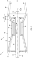
- the exhaust duct 64 of FIGS. 4 and 5 extends longitudinally along a longitudinal centerline 94 between and to an inlet 96 to the exhaust duct 64 and an outlet 98 from the exhaust duct 64, which longitudinal centerline 94 may be coaxial with one or more of the rotational axes 46 and/or 88; see also FIG. 1 .
- the exhaust duct 64 is connected to the engine case 66.
- the exhaust duct 64 of FIG. 5 for example, is mechanically fastened to an aft and/or downstream portion 100 of the engine case 66 housing the turbine section 62 at the duct inlet 96.
- the duct outlet 98 forms the combustion products exhaust 74.
- the exhaust duct 64 thereby projects longitudinally out from the turbine section portion 100 of the engine case 66 to the combustion products exhaust 74.
- the exhaust duct 64 includes an inlet section 102, an outlet section 103 and a transition section 104.
- the inlet section 102 forms the duct inlet 96.
- the inlet section 102 of FIG. 5 is disposed longitudinally between (a) the turbine section 62 / the engine case 66 and (b) the electric machine 30 along the longitudinal centerline 94.
- the inlet section 102 has a (e.g., cross-sectional) annular geometry when viewed, for example, in a reference plane perpendicular to the longitudinal centerline 94 and/or the flowpath 70 at a point of interest along the inlet section 102.
- the annular geometry of FIG. 6 has a circular shape. This annular geometry may be uniform along a longitudinal length of the inlet section 102. Alternatively, the annular geometry may (e.g., slightly) change along at least a portion of the longitudinal length of the inlet section 102. The present disclosure, however, is not limited to such an exemplary annular shape.
- the outlet section 103 forms the duct outlet 98 and the combustion products exhaust 74.
- the outlet section 103 longitudinally overlaps the electric machine 30 along the longitudinal centerline 94.
- the outlet section 103 of FIG. 5 for example, extends longitudinally along the electric machine 30 to the combustion products exhaust 74.
- the outlet section 103 has a (e.g., cross-sectional) non-annular geometry when viewed, for example, in a reference plane perpendicular to the longitudinal centerline 94 and/or the flowpath 70 at a point of interest along the outlet section 103.
- the non-annular geometry of FIG. 7 is an arcuate geometry with, for example, a crescent shape.
- This non-annular geometry may be uniform along a longitudinal length of the outlet section 103.
- the non-annular geometry may (e.g., slightly) change along at least a portion of the longitudinal length of the outlet section 103.
- the present disclosure is not limited to such an exemplary non-annular geometry.
- the non-annular geometry of the outlet section 103 may have a circular segment shape or a polygonal shape.
- the transition section 104 connects the outlet section 103 to the inlet section 102.
- the transition section 104 of FIGS. 5 and 6 extends longitudinally between and to the inlet section 102 and the outlet section 103.
- the transition section 104 longitudinally overlaps the electric machine 30 along the longitudinal centerline 94.
- An aft and/or downstream portion of the transition section 104 of FIG. 5 for example, extends longitudinally along the electric machine 30 to the outlet section 103.
- a forward and/or upstream portion of the transition section 104 of FIG. 5 may be disposed longitudinally between (a) the inlet section 102 and (b) the electric machine 30 along the longitudinal centerline 94. Referring to FIG.
- the transition section 104 has a (e.g., cross-sectional) non-annular geometry when viewed, for example, in a reference plane perpendicular to the longitudinal centerline 94 and/or the flowpath 70 at a point of interest along the transition section 104.
- the non-annular geometry of FIG. 8 is an arcuate geometry.
- This non-annular geometry of the transition section 104 changes along at least a portion or an entirety of a longitudinal length of the transition section 104 to provide a (e.g., gradual) transition between the annular geometry of the inlet section 102 and the non-annular geometry of the outlet section 103.
- the exhaust sections 102-104 of FIGS. 4 and 5 are configured to provide the exhaust duct 64 with a side pocket 106, e.g., a groove, an indentation, a recession, a channel, etc.
- This side pocket 106 is outside of the flowpath 70 and, more particularly, separated from the flowpath 70 by an exterior sidewall 108 of the exhaust duct 64.
- the side pocket 106 is thereby disposed next to the exhaust duct 64 and its sidewall 108.
- the electric machine 30 may be arranged at least partially within the side pocket 106.
- One or more of the duct sections 103 and/or 104 may each extend (e.g., wrap) circumferentially about the electric machine 30 (and the longitudinal centerline 94) between opposing circumferential sides 110A and 110B (generally referred to as "110") of the exhaust duct 64.
- the electric machine 30 may be aligned with the gas turbine engine 32 (e.g., the rotational axes 46 and 88 may be at least substantially coaxial).
- the electric machine 30 may also project (e.g., vertically and/or laterally) out of the side pocket 106 and away from the exhaust duct 64 such that at least a portion of an exterior of the electric machine 30 and its machine case 48 is exposed to air (e.g., relatively cool air, ambient air, etc.) outside of and away from the exhaust duct 64.
- air e.g., relatively cool air, ambient air, etc.
- Such an arrangement may (e.g., significantly) reduce cooling requirements for the electric machine 30.
- one or more service lines e.g., the electrical lead(s) 50 and/or the fluid conduit(s) 58
- the electric machine 5 may be routed (e.g., directly) to the electric machine 30, for example without passing through (or near) the exhaust duct 64 and/or without passing across the flowpath 70. This may facilitate arranging one or more of the system components 56 (see FIG. 2 ) remote from the electric machine 30; e.g., outside of the engine case 66 and/or outside of the powerplant 24.
- the exhaust duct 64 may extend (e.g., wrap) circumferentially around the electric machine 30 less than two-hundred and seventy degrees (270°).
- the downstream portion of the transition section 104 may extend circumferentially around the electric machine 30 (depending on longitudinal location) between one-hundred and twenty degrees (120°) and two-hundred and seventy degrees (270°); e.g., between one-hundred and sixty degrees (160°) and two-hundred degrees (200°).
- the outlet section 103 may extend circumferentially around the electric machine 30 (depending on longitudinal location) between twenty or thirty degrees (20-30°) and one-hundred and sixty degrees (160°); e.g., between forty-five degrees (45°) and one-hundred and twenty degrees (120°).
- the exhaust duct 64 may follow a non-straight trajectory away from the longitudinal centerline 94.
- the exhaust duct 64 of FIG. 1 turns away from the electric machine 30 in a vertical downward direction; e.g., relative to gravity when the longitudinal centerline 94 is horizontally level.
- the exhaust duct 64 may alternatively turn away from the electric machine 30 in a vertical upward direction (e.g., the exhaust duct 64 may be rotated 180° about the longitudinal centerline 94) and/or in a laterally sideways direction (e.g., the exhaust duct 64 may be rotated 90° about the longitudinal centerline 94).
- the exhaust duct 64 may include a jog to offset the outlet section 103 outward from the inlet section 102 and/or the electric machine 30.
Landscapes
- Engineering & Computer Science (AREA)
- Mechanical Engineering (AREA)
- Chemical & Material Sciences (AREA)
- Combustion & Propulsion (AREA)
- General Engineering & Computer Science (AREA)
- Aviation & Aerospace Engineering (AREA)
- Power Engineering (AREA)
- Connection Of Motors, Electrical Generators, Mechanical Devices, And The Like (AREA)
- Supercharger (AREA)
Applications Claiming Priority (1)
| Application Number | Priority Date | Filing Date | Title |
|---|---|---|---|
| US18/088,214 US12583609B2 (en) | 2022-12-23 | 2022-12-23 | Exhaust duct for hybrid aircraft powerplant |
Publications (1)
| Publication Number | Publication Date |
|---|---|
| EP4390063A1 true EP4390063A1 (fr) | 2024-06-26 |
Family
ID=89321990
Family Applications (1)
| Application Number | Title | Priority Date | Filing Date |
|---|---|---|---|
| EP23219440.7A Pending EP4390063A1 (fr) | 2022-12-23 | 2023-12-21 | Conduit d'échappement pour centrale électrique d'aéronef hybride |
Country Status (3)
| Country | Link |
|---|---|
| US (1) | US12583609B2 (fr) |
| EP (1) | EP4390063A1 (fr) |
| CA (1) | CA3222164A1 (fr) |
Families Citing this family (1)
| Publication number | Priority date | Publication date | Assignee | Title |
|---|---|---|---|---|
| US20250263173A1 (en) * | 2024-02-20 | 2025-08-21 | Pratt & Whitney Canada Corp. | Exhaust duct mounting structure for hybrid aircraft powerplant |
Citations (2)
| Publication number | Priority date | Publication date | Assignee | Title |
|---|---|---|---|---|
| US10717539B2 (en) * | 2016-05-05 | 2020-07-21 | Pratt & Whitney Canada Corp. | Hybrid gas-electric turbine engine |
| US20220302801A1 (en) * | 2021-03-18 | 2022-09-22 | General Electric Company | Bearing current mitigation for an electric machine embedded in a gas turbine engine |
Family Cites Families (14)
| Publication number | Priority date | Publication date | Assignee | Title |
|---|---|---|---|---|
| US8286415B2 (en) * | 2006-10-12 | 2012-10-16 | United Technologies Corporation | Turbofan engine having inner fixed structure including ducted passages |
| US8317129B1 (en) | 2009-03-25 | 2012-11-27 | The Boeing Company | Universal convergent nozzle and distinct nozzle aperture |
| EP2964921B1 (fr) * | 2013-03-07 | 2019-10-16 | Rolls-Royce Corporation | Moteur à turbine à gaz à arbres multiples |
| US10267263B2 (en) | 2016-08-08 | 2019-04-23 | United Technologies Corporation | Exhaust duct for turbine forward of fan |
| US20180051627A1 (en) | 2016-08-17 | 2018-02-22 | United Technologies Corporation | Gas generator bifurcating exhaust duct to free turbine |
| US11371379B2 (en) | 2017-08-22 | 2022-06-28 | General Electric Company | Turbomachine with alternatingly spaced turbine rotor blades |
| GB201910009D0 (en) | 2019-07-12 | 2019-08-28 | Rolls Royce Plc | Gas turbine engine electrical generator |
| GB201910008D0 (en) | 2019-07-12 | 2019-08-28 | Rolls Royce Plc | Gas turbine engine electrical generator |
| GB201910011D0 (en) | 2019-07-12 | 2019-08-28 | Rolls Royce Plc | Gas turbine engine electrical generator |
| GB201910010D0 (en) | 2019-07-12 | 2019-08-28 | Rolls Royce Plc | Gas turbine engine electrical generator |
| US12366217B2 (en) * | 2022-12-21 | 2025-07-22 | General Electric Company | Electric machine assembly |
| US12246844B1 (en) * | 2023-11-29 | 2025-03-11 | Pratt & Whitney Canada Corp. | Hybrid aircraft power plant |
| US20250263173A1 (en) * | 2024-02-20 | 2025-08-21 | Pratt & Whitney Canada Corp. | Exhaust duct mounting structure for hybrid aircraft powerplant |
| US20250297579A1 (en) * | 2024-03-25 | 2025-09-25 | Rtx Corporation | Open pusher rotor with remote exhaust |
-
2022
- 2022-12-23 US US18/088,214 patent/US12583609B2/en active Active
-
2023
- 2023-12-05 CA CA3222164A patent/CA3222164A1/fr active Pending
- 2023-12-21 EP EP23219440.7A patent/EP4390063A1/fr active Pending
Patent Citations (2)
| Publication number | Priority date | Publication date | Assignee | Title |
|---|---|---|---|---|
| US10717539B2 (en) * | 2016-05-05 | 2020-07-21 | Pratt & Whitney Canada Corp. | Hybrid gas-electric turbine engine |
| US20220302801A1 (en) * | 2021-03-18 | 2022-09-22 | General Electric Company | Bearing current mitigation for an electric machine embedded in a gas turbine engine |
Also Published As
| Publication number | Publication date |
|---|---|
| US20240208664A1 (en) | 2024-06-27 |
| US12583609B2 (en) | 2026-03-24 |
| CA3222164A1 (fr) | 2024-06-23 |
Similar Documents
| Publication | Publication Date | Title |
|---|---|---|
| EP3957843B1 (fr) | Moteur à turbine à gaz hybride avec moteur électrique et générateur électrique | |
| US12116939B2 (en) | Hybrid transmission on propeller gearbox | |
| EP3767080A2 (fr) | Moteur/générateur thermiquement protégé pour moteur à turbine à gaz | |
| US10641124B2 (en) | Hybrid electric turbine engine | |
| EP3885551A1 (fr) | Systèmes et procédés pour moteurs à turbine électrique hybride | |
| US12503241B2 (en) | Thermal management assembly for an aircraft propulsion system | |
| EP4286657A1 (fr) | Moteur à turbine à gaz avec machine électrique dans le réacteur de base du moteur | |
| EP4390063A1 (fr) | Conduit d'échappement pour centrale électrique d'aéronef hybride | |
| US20240208663A1 (en) | Hybrid aircraft propulsion system with remotely located electric machine | |
| EP4607007A1 (fr) | Structure de montage de conduit d'échappement pour centrale électrique d'aéronef hybride | |
| EP4509703A1 (fr) | Groupe motopropulseur d'aéronef avec groupe motopropulseur électrique | |
| EP4389605A2 (fr) | Unité(s) de propulsion électrique d'aéronef avec rotors de propulseurs multiples | |
| CN112969843B (zh) | 设置有电机的飞行器涡轮发动机 | |
| US20250326491A1 (en) | Thermal management assembly for a hybrid-electric aircraft propulsion system | |
| EP4438879A1 (fr) | Couplage de puissance entre un ensemble rotatif de moteur et un dispositif externe | |
| EP4553309A1 (fr) | Système d'accessoire de moteur à turbine à boîtes de vitesses multiples | |
| US12595746B2 (en) | Aircraft propulsion system with clocked electric machine and accessory gearbox | |
| US12215630B2 (en) | Flex coupler for hybrid gas turbine engine powerplant | |
| US12523161B1 (en) | Aircraft powerplant gearbox with selectable power coupler | |
| US12404811B1 (en) | Aircraft powerplant gearbox with selectable power coupler |
Legal Events
| Date | Code | Title | Description |
|---|---|---|---|
| PUAI | Public reference made under article 153(3) epc to a published international application that has entered the european phase |
Free format text: ORIGINAL CODE: 0009012 |
|
| STAA | Information on the status of an ep patent application or granted ep patent |
Free format text: STATUS: THE APPLICATION HAS BEEN PUBLISHED |
|
| AK | Designated contracting states |
Kind code of ref document: A1 Designated state(s): AL AT BE BG CH CY CZ DE DK EE ES FI FR GB GR HR HU IE IS IT LI LT LU LV MC ME MK MT NL NO PL PT RO RS SE SI SK SM TR |
|
| STAA | Information on the status of an ep patent application or granted ep patent |
Free format text: STATUS: REQUEST FOR EXAMINATION WAS MADE |
|
| 17P | Request for examination filed |
Effective date: 20250102 |