EP4390084A1 - Stromanschluss für turbomaschine - Google Patents
Stromanschluss für turbomaschine Download PDFInfo
- Publication number
- EP4390084A1 EP4390084A1 EP22215418.9A EP22215418A EP4390084A1 EP 4390084 A1 EP4390084 A1 EP 4390084A1 EP 22215418 A EP22215418 A EP 22215418A EP 4390084 A1 EP4390084 A1 EP 4390084A1
- Authority
- EP
- European Patent Office
- Prior art keywords
- power connector
- bolts
- power
- base bodies
- housing
- Prior art date
- Legal status (The legal status is an assumption and is not a legal conclusion. Google has not performed a legal analysis and makes no representation as to the accuracy of the status listed.)
- Granted
Links
Images





Classifications
-
- F—MECHANICAL ENGINEERING; LIGHTING; HEATING; WEAPONS; BLASTING
- F02—COMBUSTION ENGINES; HOT-GAS OR COMBUSTION-PRODUCT ENGINE PLANTS
- F02B—INTERNAL-COMBUSTION PISTON ENGINES; COMBUSTION ENGINES IN GENERAL
- F02B37/00—Engines characterised by provision of pumps driven at least for part of the time by exhaust
- F02B37/04—Engines with exhaust drive and other drive of pumps, e.g. with exhaust-driven pump and mechanically-driven second pump
- F02B37/10—Engines with exhaust drive and other drive of pumps, e.g. with exhaust-driven pump and mechanically-driven second pump at least one pump being alternatively or simultaneously driven by exhaust and other drive, e.g. by pressurised fluid from a reservoir or an engine-driven pump
-
- F—MECHANICAL ENGINEERING; LIGHTING; HEATING; WEAPONS; BLASTING
- F02—COMBUSTION ENGINES; HOT-GAS OR COMBUSTION-PRODUCT ENGINE PLANTS
- F02B—INTERNAL-COMBUSTION PISTON ENGINES; COMBUSTION ENGINES IN GENERAL
- F02B39/00—Component parts, details, or accessories relating to, driven charging or scavenging pumps, not provided for in groups F02B33/00 - F02B37/00
- F02B39/02—Drives of pumps; Varying pump drive gear ratio
- F02B39/08—Non-mechanical drives, e.g. fluid drives having variable gear ratio
- F02B39/10—Non-mechanical drives, e.g. fluid drives having variable gear ratio electric
-
- F—MECHANICAL ENGINEERING; LIGHTING; HEATING; WEAPONS; BLASTING
- F16—ENGINEERING ELEMENTS AND UNITS; GENERAL MEASURES FOR PRODUCING AND MAINTAINING EFFECTIVE FUNCTIONING OF MACHINES OR INSTALLATIONS; THERMAL INSULATION IN GENERAL
- F16B—DEVICES FOR FASTENING OR SECURING CONSTRUCTIONAL ELEMENTS OR MACHINE PARTS TOGETHER, e.g. NAILS, BOLTS, CIRCLIPS, CLAMPS, CLIPS OR WEDGES; JOINTS OR JOINTING
- F16B35/00—Screw-bolts; Stay-bolts; Screw-threaded studs; Screws; Set screws
- F16B35/04—Screw-bolts; Stay-bolts; Screw-threaded studs; Screws; Set screws with specially-shaped head or shaft in order to fix the bolt on or in an object
- F16B35/06—Specially-shaped heads
-
- H—ELECTRICITY
- H01—ELECTRIC ELEMENTS
- H01R—ELECTRICALLY-CONDUCTIVE CONNECTIONS; STRUCTURAL ASSOCIATIONS OF A PLURALITY OF MUTUALLY-INSULATED ELECTRICAL CONNECTING ELEMENTS; COUPLING DEVICES; CURRENT COLLECTORS
- H01R11/00—Individual connecting elements providing two or more spaced connecting locations for conductive members which are, or may be, thereby interconnected, e.g. end pieces for wires or cables supported by the wire or cable and having means for facilitating electrical connection to some other wire, terminal, or conductive member, blocks of binding posts
- H01R11/11—End pieces or tapping pieces for wires, supported by the wire and for facilitating electrical connection to some other wire, terminal or conductive member
- H01R11/26—End pieces terminating in a screw clamp, screw or nut
Definitions
- the present disclosure generally relates to a turbomachine and, more particularly, relates to a turbomachine with an electrical assist unit having a power connector associated therewith.
- turbomachines e.g., turbochargers, superchargers, motorized turbomachines, turbogenerators, etc.
- turbomachines may extract energy mechanically using a rotating shaft.
- this energy is extracted from the exhaust of an internal combustion engine, which causes rotation of the shaft and a boost in intake charge pressure (such as intake air pressure) by the compressor.
- a supercharger may boost intake charge pressure using a compressor powered by energy extracted from a drive shaft or similar.
- electric compressors can improve the dynamic response of the system and provide an on-demand boost that can mitigate against high amounts of transient emissions and reduce turbocharge lag.
- This electrical energy may be provided via a battery, where battery cables are connected to a power connector of the electric compressor.
- a power connector is the bolted power connecter, in which the cables from a battery are fixed onto bolts of the power connector using nuts via a screwed connection.
- a power connector allows for connection of a power source to an electric assist unit of a compressor, for example a compressor of an internal combustion engine.
- the power connector includes first and second bolts, wherein the first and second bolts each comprise a base body and a shank, the shank having a thread formed on an outer surface thereof; and a housing connected to the first and second bolts.
- the base bodies of the first and second bolts comprise gradual transitions from each side of the base body to another side, each gradual transition having a radius of curvature. A diagonal gap of uniform width is present between the base bodies of the first and second bolts.
- a method of manufacturing the power connector includes forming the bolts of the power connector; and connecting the bolts to the housing of the power connector
- an e-assist turbocharger in an additional embodiment, includes a housing; a rotating group including a shaft, a first wheel member fixed to the shaft, a second wheel member; an electric assist unit configured to rotate the rotating group; a power source comprising cables, and the power connector described above, wherein the power connector is arranged to electrically connect cables of the power source to the electric assist unit.
- example embodiments disclosed herein provide an improved power connector for connecting a power source to an electric assist unit of a compressor of an internal combustion engine.
- Embodiments also include improved methods of manufacturing turbomachines with the improved electric compressor.
- the embodiments of the power connector as described herein typically improve manufacturing efficiency, improve the serviceable lifespan of the power connector, and have additional benefits as will be described below.
- the power connector is a power connector for connecting a power source to an electric assist unit of a compressor of an internal combustion engine.
- the power connector includes first and second bolts, wherein the first and second bolts each comprise a base body and a shank, the shank having a thread formed on an outer surface thereof; a housing connected to the first and second bolts.
- the base bodies of the first and second bolts comprise gradual transitions from each side of the base body to another side, each gradual transition having a radius of curvature. A diagonal gap of uniform width is present between the base bodies of the first and second bolts.
- the above-described power connector provides a number of advantages.
- high tightening forces are used.
- a tightening torque of 20 Nm is typically applied when an M8-sized bolted connection is used to connect these power cables to the electric assist unit, and other high tightening torques are similarly used with other sizes of bolted connections.
- this high tightening torque may cause micro-fractures or other defects in various locations of the power connector which can act as crack initiators which, over the multiple thermal cycles that will experienced during operation of an electric assist unit for a compressor, cause propagation of thermal cracks. Increased thermal cracking reduces the useful service life of the power connector.
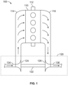
- FIG. 1 is a schematic view of a known system 100 including an internal combustion engine 110 and turbocharger 120 without an electric compressor associated therewith.
- the internal combustion engine 110 includes an engine block housing one or more combustion chambers that operatively drive a shaft 112.
- an intake port 114 provides a flow path for a combustion gas, for example air, to the engine block while an exhaust port 116 provides a flow path for exhaust from the engine block.
- the turbocharger 120 acts to extract energy from the exhaust and to use this energy to boost intake charge pressure, for example the pressure of the combustion gas.
- the turbocharger 120 includes a shaft 122 having a compressor 124, a turbine 126, an intake 134 and an exhaust outlet 136.
- a turbocharger may help to provide a larger mass of combustion gas to the engine, which allows for greater engine output during combustion.
- an exemplary system 200 including a turbocharger 220 and an internal combustion engine 110.
- the turbocharger includes a combustion gas inlet 134, a shaft 122, a compressor 124, a turbine 126, and an electric assist unit 240 associated with the compressor 124.
- the electric assist unit 240 is electrically connected to a power source 250.
- the power source 250 comprises a battery, such as a 48V battery, and the electrical assist unit 240 comprises a +7kw motor.
- the power source 250 is operably connected to a generator 260.
- the generator 260 may be powered by the internal combustion engine 110. In alternative embodiments, the generator 260 may be powered by a separate power source (not shown).
- the electrical assist unit 240 powers the compressor 124. This is different to the arrangement in FIG. 1 , where exhaust from the engine 110 completely powers the compressor 124.
- Using the electrical assist unit 240 to power the compressor 224 allows for a reduction in the phenomenon known as turbocharger lag and also improves the dynamic response of the turbocharger.
- a dedicated power source 250 is used to power the electric assist unit 240.
- a power connector may be used.
- a power connector may also be used to connect a non-dedicated power source (such as the 12V car battery - not shown) to the electric assist unit 240.
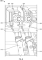
- a power connector 300 not according to the present invention is shown in FIG. 3 .
- cables 310 of the power source for example a dedicated 48V battery
- nuts 320 that compress cable connectors 330 to bolt bases (not shown in this figure) of bolts.
- the nuts 320 are screwed onto shanks 350 of the bolts, which shanks 350 have a thread disposed on at least part of their exterior surface so as to allow for a screwed connection to be formed with corresponding threads disposed on at least part of an interior surface of the nuts 320.
- the power connector 300 also includes a housing 360.
- the housing 360 may be formed of a material that has a lower tensile strength and/or fracture strength than the bolts 340, to allow for improved ease of manufacturing, for example a plastic such as nylon.
- the housing 360 may be overmolded onto metal bolts.
- the tightening torque illustrated with arrows in FIG. 3
- the tightening torque may cause defects, micro-fractures and/or structural deformities in the housing 360 of the power connector 300, which housing 360 may have a lower tensile and/or fracture strength than the bolts of the power connector 300.
- These defects or structural deformities in the housing 360 may cause a higher likelihood of cracking in the housing 360 during thermal cycling of the power connector during operation as compared to the bolts themselves.
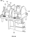
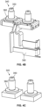
- FIG. 4A Other views of the power connector 300 are shown in FIG 4A , 4B and 4C .
- the power connector 300 including both the housing 360 and bolts 340 is shown, together with the connection of the bolts 340 to power frames 390 within the electric assist unit, which power frames 390 do not form part of the power connector 300.
- the bolts 340 include both a shank 350 and a base body 380.
- the bolts 340 of the power connector 300 are shown as being connected to the power frames 390 without the housing being present.
- the power frames 390 can be welded to the base bodies of the bolts or simply placed on the base bodies.
- the power frames 390 may be constructed from copper.
- FIG. 4C the bolts 340 of the power connector 300 are shown in isolation.
- the present inventors performed investigative efforts, including performing a finite element computational analysis to determine where the stress caused by this tightening torque would be concentrated.
- FIG. 5 the result of these investigative efforts revealed that the corners 30 of the base bodies 380 of the bolts acted as stress concentrators during the application of the tightening torque used to attach the nuts to the bolts 340, which increased the likelihood that this tightening torque results in defects or other crack initiators being formed in the housing 360 of the power connector that would be likely to reduce the service lifespan of the power connector 300.
- the term 'stress concentrator' refers to a point or area in the design where the stress is significantly higher than in surrounding areas of the part.
- the most optimum design of the base bodies 380 was not feasible due to the electrical properties of this design.
- the gradual transitions around the corners of the base bodies caused the sides of the base bodies 380 to be close enough together to cause electrical losses, such as arcing between the base bodies 380, to be introduced into the system.
- FIG. 6 shows the bolts 640 of a power connector according to the present invention
- the base bodies 680 of the bolts 640 have gradual transitions from one side of the base body 680 to another.
- the base bodies 680 may have cam-shaped topologies, such as a symmetric pear cam shape, a non-symmetric pear cam shape, an eccentric cam shape, an elliptical cam shape, a symmetric egg cam shape or a non-symmetric egg cam shape.
- cam-shaped topologies such as a symmetric pear cam shape, a non-symmetric pear cam shape, an eccentric cam shape, an elliptical cam shape, a symmetric egg cam shape or a non-symmetric egg cam shape.
- part of one base body extends beyond a part of the other base body in a plane when viewed from an axis parallel to the shanks 650, such that an overlap is created in this plane.
- Such an overlap allows for particularly effective stress reduction in the power connector.
- a diagonal gap 685 of uniform width is present between the two base bodies 680.
- the inclusion of such a diagonal gap 685 allows for gradual transitions of the corners of the base bodies 680 to reduce the stress concentrations in the power connector during application of a tightening torque whilst still allowing for the prevention of the introduction of sources of electrical losses, such as arcing, into the design as a result of the new gradual transitions. It was further discovered that a non-diagonal gap of uniform width between the base bodies was less preferred, from a stress concentration reduction perspective, as compared to a diagonal gap 685.
- a diagonal gap refers to a gap between the base bodies 680 that has a first end of the gap located closer to the shank 650 of a first one of the bolts 640 as compared to the shank 650 of a second one of the bolts 640, and has a second end of the gap located closer to the shank 650 of the second one of the bolts 640 as compared to the shank 650 of the first one of the bolts 640.
- the diagonal gap 685 has a uniform width that is, at a minimum, approximately the same size as half of the width of the nuts 320 screwed onto the shanks 650 of the bolts 640. It has been shown by the present inventors that a diagonal gap 685 of this width is the minimum needed to prevent arcing between the bolts 640 when the power source is a battery of around 48V. A diagonal gap 685 of this width therefore allows for a compact power connector design that still ensures that sources of major electrical loss are not introduced into the design. In the case of a M8 connecting nut, which has a width of around 8mm, the minimum width of the diagonal gap 685 is around 4mm.
- FIG. 7 shows a comparison of the bolts 340 and associated base bodies 380 of the power connector shown in FIG. 3 and the improved bolts 640 and associated base bodies 680 of the power connector shown in FIG. 6 according to embodiments of the present invention.
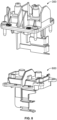
- FIG. 8 shows a comparison of the power connector 300 shown in FIG. 3 and the improved power connector 600 according to embodiments of the present invention.
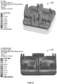
- FIG. 9 shows finite element analysis models of the power connector 300 shown in FIG. 3 and the improved power connector 600 according to embodiments of the present invention.
- Each of the models shown in FIG. 9 shows areas of stress for the respective power connector model in Mega Pascals (MPa).
- MPa Mega Pascals
- the maximum amount of stress incurred during a tightening torque of 20 Nm on a shank in the power connector 300 shown in FIG. 3 was 56.878 MPa.
- the maximum amount of stress incurred during a tightening torque of 20 Nm on a shank in the improved power connector 600 according to embodiments of the present invention was only 14.451 MPa.
- the base bodies 680 of the bolts 640 of the improved power connector may be constructed with a reduced height as compared to the bolts with square-type base bodies 380, as shown in the power connector 300 shown in FIG. 3 , thereby allowing for a more compact power connector.
- the improved power connector 600 also reduces stress concentration in the power connector 600 arising from the tensile load placed upon the power connector by the cables of the power source, which may be a tensile load on the order of around 100N.
- the design of the improved power connector therefore also improved the service lifespan of the power connector due to the reduced likelihood of failure occurring due to this continual tensile load as well as the torsional force applied during tightening of nuts to the shanks 650 of the bolts 640.
- one or more relief notches may be included in the design of the base bodies 680 so as to provide additional mitigation against stress concentration.
- FIGs. 10A, 10B, 10C and 10D show top, bottom, side and three-dimensional views of the improved power connector 600.
- one or more holes 700 may be provided in the housing 660 of the improved power connector 600 to allow for a screwed connection of the power connector 600 to the electric assist unit (not shown in these figures).
- the bolts of the power connector are formed.
- the base bodies of these bolts have gradual transitions between sides of the base bodies.
- These bolts may be formed in a single piece out of a single material, for example by casting.
- the shanks of the bolts may be formed from a first material, such as a steel alloy with high tensile strength for withstanding high torsional loads, and the base bodies of the bolts may be formed from a second material, such as a lower cost steel or aluminum with a lower tensile strength, and the shanks and the base bodies may be assembled together, for example by welding or press-fitting.
- the bolts are connected to the housing of the power connector.
- the housing of the power connector is formed from a plastic, such as nylon, by overmolding the housing onto the assembled bolts in order to connect the bolts to the housing. In this manner, a cost-efficient, flexible manufacturing process can be implemented to fabricate the improved power connector.
- the bolts are attached to the housing by mechanical means, such as by a latching mechanism or by clamping.
- the improved power connector, the manufacturing methods thereof, and other features of the present disclosure provide a number of advantages. These features increase the service life of the improved power connector as compared to other designs of power connectors.
Landscapes
- Engineering & Computer Science (AREA)
- Chemical & Material Sciences (AREA)
- Combustion & Propulsion (AREA)
- Mechanical Engineering (AREA)
- General Engineering & Computer Science (AREA)
- Supercharger (AREA)
Priority Applications (1)
| Application Number | Priority Date | Filing Date | Title |
|---|---|---|---|
| EP22215418.9A EP4390084B1 (de) | 2022-12-21 | 2022-12-21 | Stromanschluss für turbomaschine |
Applications Claiming Priority (1)
| Application Number | Priority Date | Filing Date | Title |
|---|---|---|---|
| EP22215418.9A EP4390084B1 (de) | 2022-12-21 | 2022-12-21 | Stromanschluss für turbomaschine |
Publications (2)
| Publication Number | Publication Date |
|---|---|
| EP4390084A1 true EP4390084A1 (de) | 2024-06-26 |
| EP4390084B1 EP4390084B1 (de) | 2026-02-04 |
Family
ID=84569369
Family Applications (1)
| Application Number | Title | Priority Date | Filing Date |
|---|---|---|---|
| EP22215418.9A Active EP4390084B1 (de) | 2022-12-21 | 2022-12-21 | Stromanschluss für turbomaschine |
Country Status (1)
| Country | Link |
|---|---|
| EP (1) | EP4390084B1 (de) |
Citations (3)
| Publication number | Priority date | Publication date | Assignee | Title |
|---|---|---|---|---|
| EP2039932A1 (de) * | 2006-07-11 | 2009-03-25 | Sanden Corporation | Abgedichtete klemmenvorrichtung für elektrischen verdichter |
| US20190120125A1 (en) * | 2016-07-15 | 2019-04-25 | Ihi Corporation | Electric turbocharger |
| US20200135377A1 (en) * | 2017-06-26 | 2020-04-30 | Borgwarner Inc. | Throttle for electrically-driven charging devices |
-
2022
- 2022-12-21 EP EP22215418.9A patent/EP4390084B1/de active Active
Patent Citations (3)
| Publication number | Priority date | Publication date | Assignee | Title |
|---|---|---|---|---|
| EP2039932A1 (de) * | 2006-07-11 | 2009-03-25 | Sanden Corporation | Abgedichtete klemmenvorrichtung für elektrischen verdichter |
| US20190120125A1 (en) * | 2016-07-15 | 2019-04-25 | Ihi Corporation | Electric turbocharger |
| US20200135377A1 (en) * | 2017-06-26 | 2020-04-30 | Borgwarner Inc. | Throttle for electrically-driven charging devices |
Also Published As
| Publication number | Publication date |
|---|---|
| EP4390084B1 (de) | 2026-02-04 |
Similar Documents
| Publication | Publication Date | Title |
|---|---|---|
| JP5477866B2 (ja) | 新規で高められたスーパチャージ内燃機関、及びシステム | |
| US20100054934A1 (en) | Exhaust gas turbocharger | |
| US9925862B2 (en) | Turbine compressor wheel with axially extended blades | |
| JP2009079487A (ja) | エンジンの過給装置 | |
| KR20150024281A (ko) | 터보차저를 위한 장치 | |
| KR101299108B1 (ko) | 전기식 액추에이터 | |
| EP4390084B1 (de) | Stromanschluss für turbomaschine | |
| US20160076582A1 (en) | Vibration resistant flex flange ball stud | |
| US8419334B2 (en) | Magnetized nut for fastening a compressor wheel of an exhaust turbocharger to the turbo shaft, and method for the production thereof | |
| US11459939B2 (en) | Internal combustion engine with cooling assist system for manifold intake temperature reduction | |
| CN212296605U (zh) | 双蜗壳涡轮增压器 | |
| US20050123417A1 (en) | Turbocharger assembly and method | |
| EP0986698A1 (de) | Lader für verbrennungsmotor | |
| US7694667B2 (en) | Apparatus for a vehicle | |
| US10876547B2 (en) | Compressor wheel and shaft assembly | |
| CN1029795C (zh) | 压缩机组 | |
| AU2019325994B2 (en) | A hub-less and nut-less turbine wheel and compressor wheel design for turbochargers | |
| US7281528B2 (en) | Method and apparatus for a mechanically driven supercharger | |
| US20200116153A1 (en) | Hub-Less And Nut-Less Turbine Wheel And Compressor Wheel Design For Turbochargers | |
| EP0215754A1 (de) | Einrichtung zur Aufladung eines mehrzylindrigen Verbrennungsmotors | |
| CN103899409A (zh) | 双涡轮动能回收装置及具有该装置的车辆 | |
| CN223578036U (zh) | 一种柴油发动机用电增压器 | |
| CN113847149A (zh) | 用于运行具有电动辅助的废气驱动的增压装置的内燃机的方法和设备 | |
| EP3306049A1 (de) | Motorsystem | |
| US11668323B2 (en) | Coolant system for integrated e-machine controller for turbomachine |
Legal Events
| Date | Code | Title | Description |
|---|---|---|---|
| PUAI | Public reference made under article 153(3) epc to a published international application that has entered the european phase |
Free format text: ORIGINAL CODE: 0009012 |
|
| STAA | Information on the status of an ep patent application or granted ep patent |
Free format text: STATUS: REQUEST FOR EXAMINATION WAS MADE |
|
| 17P | Request for examination filed |
Effective date: 20221221 |
|
| AK | Designated contracting states |
Kind code of ref document: A1 Designated state(s): AL AT BE BG CH CY CZ DE DK EE ES FI FR GB GR HR HU IE IS IT LI LT LU LV MC ME MK MT NL NO PL PT RO RS SE SI SK SM TR |
|
| P01 | Opt-out of the competence of the unified patent court (upc) registered |
Free format text: CASE NUMBER: APP_41632/2024 Effective date: 20240715 |
|
| GRAP | Despatch of communication of intention to grant a patent |
Free format text: ORIGINAL CODE: EPIDOSNIGR1 |
|
| STAA | Information on the status of an ep patent application or granted ep patent |
Free format text: STATUS: GRANT OF PATENT IS INTENDED |
|
| GRAS | Grant fee paid |
Free format text: ORIGINAL CODE: EPIDOSNIGR3 |
|
| INTG | Intention to grant announced |
Effective date: 20251103 |
|
| GRAA | (expected) grant |
Free format text: ORIGINAL CODE: 0009210 |
|
| STAA | Information on the status of an ep patent application or granted ep patent |
Free format text: STATUS: THE PATENT HAS BEEN GRANTED |
|
| AK | Designated contracting states |
Kind code of ref document: B1 Designated state(s): AL AT BE BG CH CY CZ DE DK EE ES FI FR GB GR HR HU IE IS IT LI LT LU LV MC ME MK MT NL NO PL PT RO RS SE SI SK SM TR |
|
| REG | Reference to a national code |
Ref country code: CH Ref legal event code: F10 Free format text: ST27 STATUS EVENT CODE: U-0-0-F10-F00 (AS PROVIDED BY THE NATIONAL OFFICE) Effective date: 20260204 Ref country code: GB Ref legal event code: FG4D |
|
| REG | Reference to a national code |
Ref country code: DE Ref legal event code: R096 Ref document number: 602022029595 Country of ref document: DE |
|
| REG | Reference to a national code |
Ref country code: IE Ref legal event code: FG4D |