EP4390104A1 - Système et procédé de détermination de fuite d'injecteur de carburant - Google Patents
Système et procédé de détermination de fuite d'injecteur de carburant Download PDFInfo
- Publication number
- EP4390104A1 EP4390104A1 EP22215167.2A EP22215167A EP4390104A1 EP 4390104 A1 EP4390104 A1 EP 4390104A1 EP 22215167 A EP22215167 A EP 22215167A EP 4390104 A1 EP4390104 A1 EP 4390104A1
- Authority
- EP
- European Patent Office
- Prior art keywords
- fuel
- injectors
- rail
- injector
- pumping
- Prior art date
- Legal status (The legal status is an assumption and is not a legal conclusion. Google has not performed a legal analysis and makes no representation as to the accuracy of the status listed.)
- Granted
Links
Images

Classifications
-
- F—MECHANICAL ENGINEERING; LIGHTING; HEATING; WEAPONS; BLASTING
- F02—COMBUSTION ENGINES; HOT-GAS OR COMBUSTION-PRODUCT ENGINE PLANTS
- F02D—CONTROLLING COMBUSTION ENGINES
- F02D41/00—Electrical control of supply of combustible mixture or its constituents
- F02D41/22—Safety or indicating devices for abnormal conditions
-
- F—MECHANICAL ENGINEERING; LIGHTING; HEATING; WEAPONS; BLASTING
- F02—COMBUSTION ENGINES; HOT-GAS OR COMBUSTION-PRODUCT ENGINE PLANTS
- F02D—CONTROLLING COMBUSTION ENGINES
- F02D41/00—Electrical control of supply of combustible mixture or its constituents
- F02D41/22—Safety or indicating devices for abnormal conditions
- F02D41/221—Safety or indicating devices for abnormal conditions relating to the failure of actuators or electrically driven elements
-
- F—MECHANICAL ENGINEERING; LIGHTING; HEATING; WEAPONS; BLASTING
- F02—COMBUSTION ENGINES; HOT-GAS OR COMBUSTION-PRODUCT ENGINE PLANTS
- F02D—CONTROLLING COMBUSTION ENGINES
- F02D1/00—Controlling fuel-injection pumps, e.g. of high pressure injection type
- F02D1/02—Controlling fuel-injection pumps, e.g. of high pressure injection type not restricted to adjustment of injection timing, e.g. varying amount of fuel delivered
-
- F—MECHANICAL ENGINEERING; LIGHTING; HEATING; WEAPONS; BLASTING
- F02—COMBUSTION ENGINES; HOT-GAS OR COMBUSTION-PRODUCT ENGINE PLANTS
- F02D—CONTROLLING COMBUSTION ENGINES
- F02D41/00—Electrical control of supply of combustible mixture or its constituents
- F02D41/02—Circuit arrangements for generating control signals
- F02D41/14—Introducing closed-loop corrections
- F02D41/1401—Introducing closed-loop corrections characterised by the control or regulation method
-
- F—MECHANICAL ENGINEERING; LIGHTING; HEATING; WEAPONS; BLASTING
- F02—COMBUSTION ENGINES; HOT-GAS OR COMBUSTION-PRODUCT ENGINE PLANTS
- F02D—CONTROLLING COMBUSTION ENGINES
- F02D41/00—Electrical control of supply of combustible mixture or its constituents
- F02D41/30—Controlling fuel injection
- F02D41/38—Controlling fuel injection of the high pressure type
- F02D41/3809—Common rail control systems
- F02D41/3836—Controlling the fuel pressure
-
- F—MECHANICAL ENGINEERING; LIGHTING; HEATING; WEAPONS; BLASTING
- F02—COMBUSTION ENGINES; HOT-GAS OR COMBUSTION-PRODUCT ENGINE PLANTS
- F02D—CONTROLLING COMBUSTION ENGINES
- F02D41/00—Electrical control of supply of combustible mixture or its constituents
- F02D41/30—Controlling fuel injection
- F02D41/38—Controlling fuel injection of the high pressure type
- F02D41/3809—Common rail control systems
- F02D41/3836—Controlling the fuel pressure
- F02D41/3845—Controlling the fuel pressure by controlling the flow into the common rail, e.g. the amount of fuel pumped
-
- F—MECHANICAL ENGINEERING; LIGHTING; HEATING; WEAPONS; BLASTING
- F02—COMBUSTION ENGINES; HOT-GAS OR COMBUSTION-PRODUCT ENGINE PLANTS
- F02D—CONTROLLING COMBUSTION ENGINES
- F02D41/00—Electrical control of supply of combustible mixture or its constituents
- F02D41/30—Controlling fuel injection
- F02D41/38—Controlling fuel injection of the high pressure type
- F02D41/3809—Common rail control systems
- F02D41/3836—Controlling the fuel pressure
- F02D41/3863—Controlling the fuel pressure by controlling the flow out of the common rail, e.g. using pressure relief valves
-
- F—MECHANICAL ENGINEERING; LIGHTING; HEATING; WEAPONS; BLASTING
- F02—COMBUSTION ENGINES; HOT-GAS OR COMBUSTION-PRODUCT ENGINE PLANTS
- F02M—SUPPLYING COMBUSTION ENGINES IN GENERAL WITH COMBUSTIBLE MIXTURES OR CONSTITUENTS THEREOF
- F02M65/00—Testing fuel-injection apparatus, e.g. testing injection timing ; Cleaning of fuel-injection apparatus
- F02M65/006—Measuring or detecting fuel leakage of fuel injection apparatus
-
- F—MECHANICAL ENGINEERING; LIGHTING; HEATING; WEAPONS; BLASTING
- F02—COMBUSTION ENGINES; HOT-GAS OR COMBUSTION-PRODUCT ENGINE PLANTS
- F02D—CONTROLLING COMBUSTION ENGINES
- F02D41/00—Electrical control of supply of combustible mixture or its constituents
- F02D41/02—Circuit arrangements for generating control signals
- F02D41/14—Introducing closed-loop corrections
- F02D41/1401—Introducing closed-loop corrections characterised by the control or regulation method
- F02D2041/1409—Introducing closed-loop corrections characterised by the control or regulation method using at least a proportional, integral or derivative controller
-
- F—MECHANICAL ENGINEERING; LIGHTING; HEATING; WEAPONS; BLASTING
- F02—COMBUSTION ENGINES; HOT-GAS OR COMBUSTION-PRODUCT ENGINE PLANTS
- F02D—CONTROLLING COMBUSTION ENGINES
- F02D41/00—Electrical control of supply of combustible mixture or its constituents
- F02D41/22—Safety or indicating devices for abnormal conditions
- F02D2041/224—Diagnosis of the fuel system
- F02D2041/225—Leakage detection
-
- F—MECHANICAL ENGINEERING; LIGHTING; HEATING; WEAPONS; BLASTING
- F02—COMBUSTION ENGINES; HOT-GAS OR COMBUSTION-PRODUCT ENGINE PLANTS
- F02D—CONTROLLING COMBUSTION ENGINES
- F02D2200/00—Input parameters for engine control
- F02D2200/02—Input parameters for engine control the parameters being related to the engine
- F02D2200/06—Fuel or fuel supply system parameters
- F02D2200/0602—Fuel pressure
-
- F—MECHANICAL ENGINEERING; LIGHTING; HEATING; WEAPONS; BLASTING
- F02—COMBUSTION ENGINES; HOT-GAS OR COMBUSTION-PRODUCT ENGINE PLANTS
- F02M—SUPPLYING COMBUSTION ENGINES IN GENERAL WITH COMBUSTIBLE MIXTURES OR CONSTITUENTS THEREOF
- F02M63/00—Other fuel-injection apparatus having pertinent characteristics not provided for in groups F02M39/00 - F02M57/00 or F02M67/00; Details, component parts, or accessories of fuel-injection apparatus, not provided for in, or of interest apart from, the apparatus of groups F02M39/00 - F02M61/00 or F02M67/00; Combination of fuel pump with other devices, e.g. lubricating oil pump
- F02M63/02—Fuel-injection apparatus having several injectors fed by a common pumping element, or having several pumping elements feeding a common injector; Fuel-injection apparatus having provisions for cutting-out pumps, pumping elements, or injectors; Fuel-injection apparatus having provisions for variably interconnecting pumping elements and injectors alternatively
- F02M63/0225—Fuel-injection apparatus having a common rail feeding several injectors ; Means for varying pressure in common rails; Pumps feeding common rails
- F02M63/0265—Pumps feeding common rails
Definitions
- the disclosure relates generally to testing of fuel injectors of a combustion engine.
- the disclosure relates to a system and a method for determining fuel leaks.
- the disclosure can be applied in heavy-duty vehicles, such as trucks, buses, and construction equipment.
- trucks, buses, and construction equipment such as trucks, buses, and construction equipment.
- the disclosure may be described with respect to a particular vehicle, the disclosure is not restricted to any particular vehicle.
- Combustions engines may be provided with a fuel injection system comprising fuel injectors fluidly connected to a fuel rail. Fuel in the fuel rail is pressurized by one or more fuel pumps and the pressurized fuel is injected into the engine when running the engine. If the fuel injectors are worn or faulty, fuel may leak from the fuel injection system, leading to sub-optimal combustion and/or excessive fuel consumption.
- a fuel injection system is typically controlled by a control unit.
- the control unit may be connected to one or more pressure sensors adapted to measure fluid pressure in the fuel injection system, such as in the fuel rail.
- the control unit typically comprises a proportional-integral-derivative controller (PID controller) adapted to control the at least one fuel pump (4a, 4b) based on at least the fuel pressure in the fuel rail (5).
- PID controller proportional-integral-derivative controller
- the PID controller may be implemented in any suitable way, such as in software and/or hardware.
- An integral response of the PID controller represents the fuel leak rate of the fuel injection system.
- the control unit may indicate that the fuel injection system as a whole is leaky in response to the integral response exceeding a threshold value.
- a mechanic may replace all fuel injectors to mitigate the leakage.
- fuel injectors are expensive and not always available off the shelf. Accordingly, it would be advantageous to be able to identify which fuel injectors are leaking and how much they are leaking, such that only bad injectors can be replaced.
- a first aspect of the disclosure relates to a system, said system comprising a fuel injection system and a computer system comprising a processor device.
- the fuel injection system comprises:
- the integral response of the PID controller corresponds to a rate of any leak of fuel affecting the pressure in the fuel rail.
- Running the engine at a specific fuel rail pressure with a specific injector fluidly connected to the fuel rail gives a first integral response.
- Running the engine at the specific fuel rail pressure with the specific injector fluidly isolated from the fuel rail gives a second integral response.
- a baseline pressure is first established by studying the leak rate, i.e. the integral response, of the fuel injection system whilst running the engine with all fuel injectors fluidly connected to the fuel rail. The fuel rail pressure is increased until the integral response reaches a predetermined integral response threshold. The engine is then run at the baseline pressure when determining the effect of fluid isolation of each fuel injector from the fuel rail.
- Obtaining the primary reference integral responses associated with each fuel injector provides information indicating the leak rate of each fuel injector. This information enables a decision to be made as to whether or not to replace one or more fuel injectors, thereby mitigating the need of replacing all fuel injectors when the fuel injection system is leaking.
- the processor device may further be configured to, before, or after, determining the primary reference integral responses, for each fuel pump or combination of fuel pumps used together/to be used together when determining the primary reference integral responses, determine a respective baseline integral response associated with the fuel pump or combination of fuel pumps.
- Each respective baseline integral response is determined by:
- auxiliary fuel pumps it is possible to obtain primary reference integral responses for all fuel injectors using the same fuel pump(s). If only pumping fuel injectors are used as fuel pumps, not all pumping fuel injectors can be used when determining primary reference integral responses, since individual pumping fuel injectors need to be fluidly isolated from the fuel rail.
- An effect on the integral response caused by leaks of a fuel injector can be determined by comparing the primary reference integral response to the predetermined integral response threshold. However, the result of the comparison may be affected by a change in which fuel pumps are used when determining the primary reference integral responses, due to variations in integral response associated with running the fuel pumps at different rates required when reducing the number of fuel pumps as compared to the number of fuel pumps used when obtaining the baseline pressure.
- the baseline reference integral response is obtained using only those fuel pumps also used when determining the primary reference integral response for each respective fuel injector, the effects, on the integral response, of using different pumps to pressurize the fuel injection system, is accounted for by the baseline integral response(s) obtained.
- the effect on the change of which fuel pumps are used is accounted for, thereby providing more accurate information for use when determining the leak rate of each fuel injector.
- a second aspect of the disclosure relates to a method for determining fuel leak of one or more fuel injectors of a fuel injection system of a combustion engine.
- the fuel injection system comprises:
- the integral response of the PID controller corresponds to a rate of any leak of fuel affecting the pressure in the fuel rail.
- Running the engine at a specific fuel rail pressure with a specific injector fluidly connected to the fuel rail gives a first integral response.
- Running the engine at the specific fuel rail pressure with the specific injector fluidly isolated from the fuel rail gives a second integral response.
- a baseline pressure is first established by studying the leak rate, i.e. the integral response, of the fuel injection system whilst running the engine with all fuel injectors fluidly connected to the fuel rail. The fuel rail pressure is increased until the integral response reaches a predetermined integral response threshold. The engine is then run at the baseline pressure when determining the effect of fluid isolation of each fuel injector from the fuel rail.
- Obtaining the primary reference integral responses associated with each fuel injector provides information indicating the leak rate of each fuel injector. This information enables a decision to be made as to whether or not to replace one or more fuel injectors, thereby mitigating the need of replacing all fuel injectors when the fuel injection system is leaking.
- the method further comprises: c) for each fuel pump or combination of fuel pumps used together/to be used together when determining the primary reference integral responses, determining a respective baseline integral response associated with the fuel pump or combination of fuel pumps, by:
- auxiliary fuel pumps i.e. a pump not being a pump of a pumping fuel injector
- only pumping fuel injectors are used as fuel pumps, not all pumping fuel injectors can be used when determining primary reference integral responses, since individual pumping fuel injectors need to be fluidly isolated from the fuel rail.
- An effect on the integral response caused by leaks of a fuel injector can be determined by comparing the primary reference integral response to the predetermined integral response threshold.
- the result of the comparison may be affected by a change in which fuel pumps are used when determining the primary reference integral responses due to variations in integral response associated with running the fuel pumps at different rate required when reducing the number of fuel pumps as compared to the number of fuel pumps used when obtaining the baseline pressure.
- the baseline reference integral response is obtained using only those fuel pumps also used when determining the primary reference integral response for each respective fuel injector, the effects, on the integral response, of using different pumps to pressurize the fuel injection system, is accounted for by the baseline integral response(s) obtained.
- the effect on the change of which fuel pumps are used is accounted for, thereby providing more accurate information for use when determining the leak rate of each fuel injector.
- fluid isolation of a fuel injector comprises:
- fluid isolation of a fuel injector comprises: closing one or more valves between the fuel rail and the fuel injector to be fluidly isolated, such that fuel is prevented from moving between the fuel injector and the fuel rail. If the fuel injection system is provided with shut-off valves for isolation of each injector from the fuel rail, the isolation may be performed by closing the one or more valves such that fuel is prevented from moving between the fuel injector and the fuel rail.
- the fuel injection system comprises at least two fuel pumps, wherein said obtaining of the primary reference integral response for each fuel injector is performed using only one fuel pump at a time, by enabling one of the fuel pumps, and disabling the other fuel pump(s). Using only one fuel pump reduces uncertainty related to leaks of the fuel pumps.
- a subset of the fuel injectors are pumping fuel injectors, wherein each fuel pump is a pump of a respective one of the pumping fuel injectors, and wherein the obtaining of the primary reference integral response for each fuel injector comprises, for each pumping fuel injector fluidly isolated from the fuel rail, using one of the other pumping fuel injectors as the fuel pump for pressurizing the fuel rail when obtaining the primary reference integral response associated with the fluidly isolated pumping fuel injector.
- the fuel injection system comprises at least three pumping fuel injectors, wherein the method further comprises determining two reference pumping fuel injectors.
- the determination of two reference pumping fuel injectors is performed before determining the primary reference integral responses.
- the determination of the two reference pumps comprises: obtaining a secondary reference integral response for each pumping fuel injector by, for each respective pumping fuel injector:
- the method further comprises: for each respective fuel injector: determining a fuel leak value of the fuel injector, said fuel leak value being a difference between the primary reference integral response associated with the fuel injector and the respective baseline integral response, or, if no baseline integral response has been obtained, a difference between the primary reference integral response associated with the fuel injector and the predetermined integral response threshold.
- the fuel leak value indicates how much a fuel injector leaks in absolute terms, and thus enables easy comparison of the difference in leak rate of each fuel injector.
- the method further comprises comparing each fuel leak value of all fuel injectors to a predetermined first fuel leak threshold, and, in response to the fuel leak value exceeding the first fuel leak threshold, providing an indication that the fuel injector associated with the fuel leak value should be replaced.
- the method further comprises comparing a first aggregate fuel leak value to a first aggregate fuel leak threshold.
- the first aggregate fuel leak value is the sum of the respective fuel leak values of all pumping fuel injectors not yet determined to need replacement.
- the first aggregate fuel leak threshold is a second fuel leak threshold multiplied by the number of pumping fuel injectors not yet determined to need replacement.
- the second fuel leak threshold is lower than the first fuel leak threshold.
- the method further comprises, in response to the first aggregate fuel leak value exceeding the first aggregate fuel leak threshold, providing an indication that all pumping fuel injectors should be replaced.
- the method further comprises comparing a second aggregate fuel leak value to a second aggregate fuel leak threshold.
- the second aggregate fuel leak value is the sum of the respective fuel leak values of all fuel injectors except the pumping fuel injectors, and except any fuel injectors for which an indication of replacement has been provided.
- the second aggregate fuel leak threshold is a third fuel leak threshold multiplied by the number of fuel injectors of the fuel injection system except the pumping fuel injectors, and except any fuel injectors for which an indication of replacement has been provided, said third fuel leak threshold being lower than the first fuel leak threshold.
- the method further comprises, in response to the second aggregate fuel leak value exceeding the second aggregate fuel leak threshold, providing an indication that all fuel injectors not being pumping fuel injectors, should be replaced.
- a third aspect relates to a vehicle comprising the processor device to perform the method of the examples described above.
- a fourth aspect relates to a computer program product comprising program code for performing, when executed by the processor device, the method of the examples described above.
- a fifth aspect relates to a control system comprising one or more control units configured to perform the method of the examples described above.
- a sixth aspect relates to a non-transitory computer-readable storage medium comprising instructions, which when executed by the processor device, cause the processor device to perform the method of the examples described above.
- a control unit or computer system 6 of a combustion engine may indicate that the fuel injection system of the engine is leaking.
- the system and method disclosed herein enables relevant data to be obtained such that an informed decision can be made as to the rate of leak of each fuel injector. Based on the data, a mechanic can determine which fuel injectors are causing leaks and replace only such fuel injectors.
- the proposed system and method provides the relevant data in a time-efficient manner.
- the disclosure is based on a method which can be implemented in software and/or hardware, except for any manually performed steps in specific embodiments of the disclosure, such as physical removal of a fuel injector 2a, 2b from the fuel rail 5 and subsequent plugging of a port of the fuel rail 5.
- the combustion engine is an internal combustion engine, such as a diesel internal combustion engine, a gaseous internal combustion engine.
- the fuel may generally be any one of a diesel fuel and a gaseous fuel, such as a hydrogen-based fuel or the like.
- the combustion engine is an internal combustion engine for a heavy-duty vehicle, which is operable on a diesel fuel.
- a control unit or computer system 6 is provided (not shown) to monitor various sensors of the engine, such as fuel rail pressure and crankshaft position, and to control the fuel injection cycle, fuel rail pressure, etc.
- control units or computer systems 6 for running fuel injected combustion engines are known in the art and will not be described in greater detail.
- the control unit or computer system 6 used herein implements a proportional-integral-derivative controller (PID controller) which monitors fuel pressure in the fuel injection system and calculates at least an integral response.
- the integral represents a fuel leak rate of the fuel injection system.
- PID controllers are known in the art and will not be described in any greater detail herein.
- the PID controller can be implemented in any suitable way, such as by the computer system 6 or control unit running a software, or by dedicated hardware.
- the computer system 6 may include any collection of devices that individually or jointly execute a set (or multiple sets) of instructions to perform any one or more of the methodologies discussed herein.
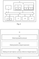
- Figs. 1 and 2 show a respective embodiment of a system comprising a fuel injection system 3 and a computer system 6 comprising a processor device 7.
- the fuel injection system 3 comprises:
- the processor device 7 is configured to: with the engine running, control the at least one fuel pump 4a, 4b to increase the pressure in the fuel rail 5 to a baseline pressure at which an integral response of the PID controller reaches a predetermined integral response threshold.
- the processor device 7 is further configured to: for each respective fuel injector 2a, 2b, determine a primary reference integral response associated with the fuel injector 2a, 2b by:
- this embodiment of the system implements an automated leak test procedure including automated fluid isolation of fuel injectors 2a, 2b, by operation of a valve (not shown) provided between each fuel injector 2a, 2b and the fuel rail 5.
- the fluid isolation could instead be enabled by the processor device 7 by stopping the engine, waiting for a mechanic to physically remove the fuel injector and plug the fuel rail, and subsequently starting the engine such that the respective primary reference integral response can be obtained.
- the processor device 7 may further be configured to:
- the present disclosure further proposes the following embodiments of a method M for determining fuel leak of one or more fuel injectors 2a, 2b of a fuel injection system 3 of a combustion engine.
- the fuel injection system 3 on which the method is used comprises:
- the method comprises:
- the method M may comprise: for each fuel pump 4a, 4b or combination of fuel pumps 4a, 4b used together/to be used together when determining the primary reference integral responses, determining a respective baseline integral response associated with the fuel pump 4a, 4b or combination of fuel pumps 4a, 4b, by:
- integral responses obtained may be stored in a memory 8. Storing of data in memory 8 may be controlled by a processor device 7.
- the fluid isolation of the fuel injector 2a, 2b may comprise: with the engine stopped, physically removing the fuel injector 2a, 2b to be fluidly isolated from the fuel rail 5 and plugging a corresponding port of the fuel rail 5. Once the respective primary reference integral response has been obtained, the fluidly isolated fuel injector 2a, 2b is re-attached to the fuel rail, thereby fluidly connecting the respective fuel injector 2a, 2b to the fuel rail 5 again such that fuel can be injected by the respective fuel injector 2a, 2b when isolating other fuel injectors and running the engine.
- the fluid isolation of a fuel injector 2a, 2b may comprises: closing one or more valves between the fuel rail 5 and the fuel injector 2a, 2b to be fluidly isolated, such that fuel is prevented from moving between the fuel injector 2a, 2b and the fuel rail 5.
- the one or more valve is opened again, thereby fluidly connecting the respective fuel injector 2a, 2b to the fuel rail 5 again such that fuel can be injected by the respective fuel injector 2a, 2b when isolating other fuel injectors and running the engine.
- the fuel injection system 3 may comprise three fuel pumps 4a, 4b.
- the determination of the primary reference integral response for each fuel injector 2a, 2b may be performed using only one fuel pump 4a, 4b at a time, by enabling one of the fuel pumps 4a, 4b, and disabling the other fuel pumps 4a, 4b.
- a subset of the fuel injectors 2b may be pumping fuel injectors 2b used as the fuel pumps 4b for supplying fuel and pressurizing the fuel injection system 3.
- the determination of the primary reference integral response for each fuel injector may comprise, for each pumping fuel injector 2b fluidly isolated from the fuel rail 5, using one of the other pumping fuel injectors 2b as the fuel pump 2b for pressurizing the fuel rail 5 when obtaining the primary reference integral response associated with the fluidly isolated pumping fuel injector 2b.
- the fuel injection system 3 may comprise at least three pumping fuel injectors 2b.
- the method may further comprise determining two reference pumping fuel injectors 2b, said determination of two reference pumping fuel injectors 2b to be performed before determining the primary reference integral responses.
- the determination of the two reference pumps comprises: obtaining a secondary reference integral response for each pumping fuel injector 2b by, for each respective pumping fuel injector 2b:
- the determination of the primary reference integral responses is performed using only the fuel pumps of the two reference pumping fuel injectors.
- the method M may comprise: for each respective fuel injector 2a, 2b: determining a fuel leak value of the fuel injector 2a, 2b, said fuel leak value being a difference between the primary reference integral response associated with the fuel injector 2a, 2b and the respective baseline integral response, or, if no baseline integral response has been obtained, a difference between the primary reference integral response associated with the fuel injector 2a, 2b and the predetermined integral response threshold.
- the method M may further comprise performing a first test (M1) by: comparing each fuel leak value of all fuel injectors 2a, 2b to a predetermined first fuel leak threshold, and, in response to the fuel leak value exceeding the first fuel leak threshold, providing an indication that the fuel injector 2a, 2b associated with the fuel leak value should be replaced. In this way, fuel injectors that leak too much can be detected and an indication for replacement provided.
- M1 a first test
- Indications may be provided in the form of data displayed on a display device or in by storing in a memory 8 data representing the indication.
- a processor device 7 may be used to control data storing or to control data display on a display device. This applies also to any further tests described below.
- Fuel injectors which leak less than the first fuel leak threshold may still be considered for further use, although further tests may indicate that they need to be replaced after all, as discussed below.
- the method M may further comprise performing a second test by comparing a first aggregate fuel leak value to a first aggregate fuel leak threshold.
- the first aggregate fuel leak value is the sum of the respective fuel leak values of all pumping fuel injectors 2b not yet determined to need replacement.
- the first aggregate fuel leak threshold is a second fuel leak threshold multiplied by the number of pumping fuel injectors 2b not yet determined to need replacement (i.e. no indication that the fuel injector 2a, 2b associated with the fuel leak value should be replaced has been provided during prior testing).
- the second fuel leak threshold is lower than the first fuel leak threshold.
- the method further comprises, in response to the first aggregate fuel leak value exceeding the first aggregate fuel leak threshold, to provide an indication that all pumping fuel injectors 2b should be replaced.
- the first test may reveal that individual fuel injectors 2a, 2b leak too much and provide an indication of replacement.
- a second test may look at the total leak of the remaining pumping fuel injectors 2b, and if the total leak rate from those fuel injectors 2b is too high indicate that all pumping fuel injectors 2b should be replaced. Such an indication is easy to interpret by a mechanic.
- the method M may further comprise performing a third test by comparing a second aggregate fuel leak value to a second aggregate fuel leak threshold.
- the second aggregate fuel leak value is the sum of the respective fuel leak values of all fuel injectors 2a except the pumping fuel injectors 2b (i.e. of a non-pumping fuel injectors), and except any fuel injectors 2a, 2b for which an indication of replacement has been provided.
- the second aggregate fuel leak threshold is a third fuel leak threshold multiplied by the number of fuel injectors 2a, 2b of the fuel injection system, except the pumping fuel injectors 2b, and except any fuel injectors 2a, 2b for which an indication of replacement has been provided.
- the third fuel leak threshold is lower than the first fuel leak threshold.
- the method further comprises, in response to the second aggregate fuel leak value exceeding the second aggregate fuel leak threshold, to provide an indication that all fuel injectors 2a not being pumping fuel injectors 2b, should be replaced.
- the present disclosure also proposes a vehicle 20 comprising the processor device 7 to perform any one of the above-described embodiments of the method M for determining fuel leak of one or more fuel injectors.
- the vehicle 20 may be a heavy-duty vehicle, such as a trucks, a bus, or construction equipment.
- control system comprising one or more control units configured to perform any one of the above-described embodiments of the method M for determining fuel leak of one or more fuel injectors.
- FIG. 4 is a schematic diagram of a computer system 6 for implementing examples disclosed herein.
- the computer system 6 is adapted to execute instructions from a computer-readable medium to perform these and/or any of the functions or processing described herein.
- the computer system 6 may be connected (e.g., networked) to other machines in a LAN, an intranet, an extranet, or the Internet. While only a single device is illustrated, the computer system 6 may include any collection of devices that individually or jointly execute a set (or multiple sets) of instructions to perform any one or more of the methodologies discussed herein.
- any reference in the disclosure and/or claims to a computer system, computing system, computer device, computing device, control system, control unit, electronic control unit (ECU), processor device, etc. includes reference to one or more such devices to individually or jointly execute a set (or multiple sets) of instructions to perform any one or more of the methodologies discussed herein.
- control system may include a single control unit or a plurality of control units connected or otherwise communicatively coupled to each other, such that any performed function may be distributed between the control units as desired.
- such devices may communicate with each other or other devices by various system architectures, such as directly or via a Controller Area Network (CAN) bus, etc.
- CAN Controller Area Network
- the computer system 6 may comprise at least one computing device or electronic device capable of including firmware, hardware, and/or executing software instructions to implement the functionality described herein.
- the computer system 6 may include a processor device 7 (may also be referred to as a control unit), a memory 8, and a system bus 14.
- the computer system 6 may include at least one computing device having the processor device 7.
- the system bus 14 provides an interface for system components including, but not limited to, the memory 8 and the processor device 7.
- the processor device 7 may include any number of hardware components for conducting data or signal processing or for executing computer code stored in memory 8.
- the processor device 7 may, for example, include a general-purpose processor, an application specific processor, a Digital Signal Processor (DSP), an Application Specific Integrated Circuit (ASIC), a Field Programmable Gate Array (FPGA), a circuit containing processing components, a group of distributed processing components, a group of distributed computers configured for processing, or other programmable logic device, discrete gate or transistor logic, discrete hardware components, or any combination thereof designed to perform the functions described herein.
- the processor device may further include computer executable code that controls operation of the programmable device.
- the system bus 14 may be any of several types of bus structures that may further interconnect to a memory bus (with or without a memory controller), a peripheral bus, and/or a local bus using any of a variety of bus architectures.
- the memory 8 may be one or more devices for storing data and/or computer code for completing or facilitating methods described herein.
- the memory 8 may include database components, object code components, script components, or other types of information structure for supporting the various activities herein. Any distributed or local memory device may be utilized with the systems and methods of this description.
- the memory 8 may be communicably connected to the processor device 7 (e.g., via a circuit or any other wired, wireless, or network connection) and may include computer code for executing one or more processes described herein.
- the memory 8 may include non-volatile memory 9 (e.g., read-only memory (ROM), erasable programmable read-only memory (EPROM), electrically erasable programmable read-only memory (EEPROM), etc.), and volatile memory 11 (e.g., random-access memory (RAM)), or any other medium which can be used to carry or store desired program code in the form of machine-executable instructions or data structures and which can be accessed by a computer or other machine with a processor device 7.
- a basic input/output system (BIOS) 10 may be stored in the non-volatile memory 9 and can include the basic routines that help to transfer information between elements within the computer system 6.
- the computer system 6 may further include or be coupled to a non-transitory computer-readable storage medium such as the storage device 15, which may comprise, for example, an internal or external hard disk drive (HDD) (e.g., enhanced integrated drive electronics (EIDE) or serial advanced technology attachment (SATA)), HDD (e.g., EIDE or SATA) for storage, flash memory, or the like.
- HDD enhanced integrated drive electronics
- SATA serial advanced technology attachment
- the storage device 15 and other drives associated with computer-readable media and computer-usable media may provide non-volatile storage of data, data structures, computer-executable instructions, and the like.
- a number of modules can be implemented as software and/or hard coded in circuitry to implement the functionality described herein in whole or in part.
- the modules may be stored in the storage device 15 and/or in the volatile memory 11, which may include an operating system 12 and/or one or more program modules 13. All or a portion of the examples disclosed herein may be implemented as a computer program product 16 stored on a transitory or non-transitory computer-usable or computer-readable storage medium (e.g., single medium or multiple media), such as the storage device 15, which includes complex programming instructions (e.g., complex computer-readable program code) to cause the processor device 7 to carry out the steps described herein.
- the computer-readable program code can comprise software instructions for implementing the functionality of the examples described herein when executed by the processor device 7.
- the processor device 7 may serve as a controller or control system for the computer system 6 that is to implement the functionality described herein.
- the computer system 6 also may include an input device interface 17 (e.g., input device interface and/or output device interface).
- the input device interface 17 may be configured to receive input and selections to be communicated to the computer system 6 when executing instructions, such as from a keyboard, mouse, touch-sensitive surface, etc.
- Such input devices may be connected to the processor device 7 through the input device interface 17 coupled to the system bus 14 but can be connected through other interfaces such as a parallel port, an Institute of Electrical and Electronic Engineers (IEEE) 1394 serial port, a Universal Serial Bus (USB) port, an IR interface, and the like.
- IEEE Institute of Electrical and Electronic Engineers
- USB Universal Serial Bus
- the computer system 6 may include an output device interface 18 configured to forward output, such as to a display, a video display unit (e.g., a liquid crystal display (LCD) or a cathode ray tube (CRT)).
- a video display unit e.g., a liquid crystal display (LCD) or a cathode ray tube (CRT)
- the computer system 6 may also include a communications interface 19 suitable for communicating with a network as appropriate or desired.
Landscapes
- Engineering & Computer Science (AREA)
- Chemical & Material Sciences (AREA)
- Combustion & Propulsion (AREA)
- Mechanical Engineering (AREA)
- General Engineering & Computer Science (AREA)
- Fuel-Injection Apparatus (AREA)
Priority Applications (3)
| Application Number | Priority Date | Filing Date | Title |
|---|---|---|---|
| EP22215167.2A EP4390104B1 (fr) | 2022-12-20 | 2022-12-20 | Système et procédé de détermination de fuite d'injecteur de carburant |
| CN202311722885.1A CN118224011A (zh) | 2022-12-20 | 2023-12-13 | 用于确定燃料喷射器泄漏的系统和方法 |
| US18/542,887 US12031495B1 (en) | 2022-12-20 | 2023-12-18 | System and a method for determining fuel injector leak |
Applications Claiming Priority (1)
| Application Number | Priority Date | Filing Date | Title |
|---|---|---|---|
| EP22215167.2A EP4390104B1 (fr) | 2022-12-20 | 2022-12-20 | Système et procédé de détermination de fuite d'injecteur de carburant |
Publications (2)
| Publication Number | Publication Date |
|---|---|
| EP4390104A1 true EP4390104A1 (fr) | 2024-06-26 |
| EP4390104B1 EP4390104B1 (fr) | 2026-02-25 |
Family
ID=84547214
Family Applications (1)
| Application Number | Title | Priority Date | Filing Date |
|---|---|---|---|
| EP22215167.2A Active EP4390104B1 (fr) | 2022-12-20 | 2022-12-20 | Système et procédé de détermination de fuite d'injecteur de carburant |
Country Status (3)
| Country | Link |
|---|---|
| US (1) | US12031495B1 (fr) |
| EP (1) | EP4390104B1 (fr) |
| CN (1) | CN118224011A (fr) |
Citations (4)
| Publication number | Priority date | Publication date | Assignee | Title |
|---|---|---|---|---|
| US20150106040A1 (en) * | 2013-10-16 | 2015-04-16 | Caterpillar Inc. | Diagnosing fault in common rail fuel system |
| DE102016119811A1 (de) * | 2016-10-18 | 2018-04-19 | Man Diesel & Turbo Se | Kraftstoffversorgungsanlage |
| FR3106857A1 (fr) * | 2020-01-30 | 2021-08-06 | Vitesco Technologies | Système de détection de carburant dans un circuit d’injection de moteur diesel |
| DE102020214226A1 (de) * | 2020-11-12 | 2022-05-12 | Vitesco Technologies Germany Gmbh | Verfahren und Vorrichtung zur Diagnose einer Injektorleckage |
Family Cites Families (5)
| Publication number | Priority date | Publication date | Assignee | Title |
|---|---|---|---|---|
| JP3713918B2 (ja) * | 1997-08-29 | 2005-11-09 | いすゞ自動車株式会社 | エンジンの燃料噴射方法及びその装置 |
| US9644556B2 (en) * | 2013-05-31 | 2017-05-09 | Ford Global Technologies, Llc | Gaseous fuel injector activation |
| US11248483B2 (en) * | 2017-06-01 | 2022-02-15 | Nanyang Technological University | Turbine housing and method of improving efficiency of a radial/mixed flow turbine |
| US10480368B2 (en) * | 2017-08-28 | 2019-11-19 | Ford Global Technologies, Llc | Systems and methods for detecting exhaust air leak |
| US10760517B2 (en) * | 2018-01-05 | 2020-09-01 | Ford Global Technologies, Llc | Systems and methods for cylinder exhaust valve diagnostics |
-
2022
- 2022-12-20 EP EP22215167.2A patent/EP4390104B1/fr active Active
-
2023
- 2023-12-13 CN CN202311722885.1A patent/CN118224011A/zh active Pending
- 2023-12-18 US US18/542,887 patent/US12031495B1/en active Active
Patent Citations (4)
| Publication number | Priority date | Publication date | Assignee | Title |
|---|---|---|---|---|
| US20150106040A1 (en) * | 2013-10-16 | 2015-04-16 | Caterpillar Inc. | Diagnosing fault in common rail fuel system |
| DE102016119811A1 (de) * | 2016-10-18 | 2018-04-19 | Man Diesel & Turbo Se | Kraftstoffversorgungsanlage |
| FR3106857A1 (fr) * | 2020-01-30 | 2021-08-06 | Vitesco Technologies | Système de détection de carburant dans un circuit d’injection de moteur diesel |
| DE102020214226A1 (de) * | 2020-11-12 | 2022-05-12 | Vitesco Technologies Germany Gmbh | Verfahren und Vorrichtung zur Diagnose einer Injektorleckage |
Also Published As
| Publication number | Publication date |
|---|---|
| US20240200503A1 (en) | 2024-06-20 |
| US12031495B1 (en) | 2024-07-09 |
| EP4390104B1 (fr) | 2026-02-25 |
| CN118224011A (zh) | 2024-06-21 |
Similar Documents
| Publication | Publication Date | Title |
|---|---|---|
| US7650778B2 (en) | Method and apparatus for testing a gear-driven fuel pump on a fuel injected IC engine | |
| US9008950B2 (en) | Pressure sensor diagnosing method and common rail fuel injection control apparatus | |
| DE102014108899B4 (de) | Verfahren und System zur Diagnose eines Common-Rail-Dieselmotors | |
| US8554454B2 (en) | Service bay high pressure common rail injector performance test | |
| KR101592402B1 (ko) | 가솔린 직접 분사 엔진의 고장 진단 방법 및 시스템 | |
| US5616837A (en) | Fuel line pressure test | |
| US12031495B1 (en) | System and a method for determining fuel injector leak | |
| US20100236528A1 (en) | Fuel pressure control strategy at engine shutdown | |
| US12116946B2 (en) | Method and evaluation unit for detecting a malfunction of a fuel system of an internal-combustion engine | |
| CN116906239A (zh) | 喷射阀故障诊断方法、装置、设备及存储介质 | |
| US10591379B2 (en) | System and method for identifying a source of high pressure leakage | |
| US20240418139A1 (en) | Method for testing a fuel injector for an internal combustion engine | |
| US20250290461A1 (en) | Systems, methods, and apparatuses for high-pressure fuel pump diagnostics | |
| CN111175040B (zh) | 限流阀的关闭油量测试方法 | |
| KR20090015565A (ko) | 커먼레일 시스템 테스트 방법 | |
| CN121712974A (zh) | 燃油泄漏诊断与燃油系统诊断管理装置、方法及系统 | |
| CN110823474B (zh) | 一种燃油系统泄漏程度评估方法及存储介质 | |
| WO2019117786A1 (fr) | Procédé de contrôle d'une fonctionnalité d'une soupape d'admission d'un élément de pompage dans un système d'injection de carburant à accumulateur haute pression | |
| KR20250168694A (ko) | 연료 시스템 내의 연료 누출의 위치특정 | |
| CN117759449A (zh) | 车辆燃油蒸发系统诊断方法、装置、设备及存储介质 | |
| WO2024175948A1 (fr) | Détection de défauts d'injecteur à l'aide d'un modèle d'apprentissage automatique | |
| CN121595127A (zh) | 检测气态燃料发动机的燃料系统泄漏的系统、方法和设备 | |
| Wierzbicki et al. | Diagnostics of a common rail system using a signal analyser |
Legal Events
| Date | Code | Title | Description |
|---|---|---|---|
| PUAI | Public reference made under article 153(3) epc to a published international application that has entered the european phase |
Free format text: ORIGINAL CODE: 0009012 |
|
| STAA | Information on the status of an ep patent application or granted ep patent |
Free format text: STATUS: THE APPLICATION HAS BEEN PUBLISHED |
|
| AK | Designated contracting states |
Kind code of ref document: A1 Designated state(s): AL AT BE BG CH CY CZ DE DK EE ES FI FR GB GR HR HU IE IS IT LI LT LU LV MC ME MK MT NL NO PL PT RO RS SE SI SK SM TR |
|
| STAA | Information on the status of an ep patent application or granted ep patent |
Free format text: STATUS: REQUEST FOR EXAMINATION WAS MADE |
|
| 17P | Request for examination filed |
Effective date: 20241115 |
|
| RBV | Designated contracting states (corrected) |
Designated state(s): AL AT BE BG CH CY CZ DE DK EE ES FI FR GB GR HR HU IE IS IT LI LT LU LV MC ME MK MT NL NO PL PT RO RS SE SI SK SM TR |
|
| GRAP | Despatch of communication of intention to grant a patent |
Free format text: ORIGINAL CODE: EPIDOSNIGR1 |
|
| STAA | Information on the status of an ep patent application or granted ep patent |
Free format text: STATUS: GRANT OF PATENT IS INTENDED |
|
| INTG | Intention to grant announced |
Effective date: 20251002 |
|
| GRAS | Grant fee paid |
Free format text: ORIGINAL CODE: EPIDOSNIGR3 |
|
| GRAA | (expected) grant |
Free format text: ORIGINAL CODE: 0009210 |
|
| STAA | Information on the status of an ep patent application or granted ep patent |
Free format text: STATUS: THE PATENT HAS BEEN GRANTED |
|
| AK | Designated contracting states |
Kind code of ref document: B1 Designated state(s): AL AT BE BG CH CY CZ DE DK EE ES FI FR GB GR HR HU IE IS IT LI LT LU LV MC ME MK MT NL NO PL PT RO RS SE SI SK SM TR |
|
| REG | Reference to a national code |
Ref country code: CH Ref legal event code: F10 Free format text: ST27 STATUS EVENT CODE: U-0-0-F10-F00 (AS PROVIDED BY THE NATIONAL OFFICE) Effective date: 20260225 Ref country code: GB Ref legal event code: FG4D |
|
| REG | Reference to a national code |
Ref country code: DE Ref legal event code: R096 Ref document number: 602022031072 Country of ref document: DE |
|
| REG | Reference to a national code |
Ref country code: IE Ref legal event code: FG4D |