EP4390120A1 - Procédé et appareil de surveillance mise en oeuvre par ordinateur d'une éolienne - Google Patents
Procédé et appareil de surveillance mise en oeuvre par ordinateur d'une éolienne Download PDFInfo
- Publication number
- EP4390120A1 EP4390120A1 EP22215852.9A EP22215852A EP4390120A1 EP 4390120 A1 EP4390120 A1 EP 4390120A1 EP 22215852 A EP22215852 A EP 22215852A EP 4390120 A1 EP4390120 A1 EP 4390120A1
- Authority
- EP
- European Patent Office
- Prior art keywords
- wind turbine
- flow control
- control device
- rotor
- active flow
- Prior art date
- Legal status (The legal status is an assumption and is not a legal conclusion. Google has not performed a legal analysis and makes no representation as to the accuracy of the status listed.)
- Pending
Links
Images

Classifications
-
- F—MECHANICAL ENGINEERING; LIGHTING; HEATING; WEAPONS; BLASTING
- F03—MACHINES OR ENGINES FOR LIQUIDS; WIND, SPRING, OR WEIGHT MOTORS; PRODUCING MECHANICAL POWER OR A REACTIVE PROPULSIVE THRUST, NOT OTHERWISE PROVIDED FOR
- F03D—WIND MOTORS
- F03D17/00—Monitoring or testing of wind motors, e.g. diagnostics
- F03D17/005—Monitoring or testing of wind motors, e.g. diagnostics using computation methods, e.g. neural networks
- F03D17/0065—Monitoring or testing of wind motors, e.g. diagnostics using computation methods, e.g. neural networks for diagnostics
-
- F—MECHANICAL ENGINEERING; LIGHTING; HEATING; WEAPONS; BLASTING
- F03—MACHINES OR ENGINES FOR LIQUIDS; WIND, SPRING, OR WEIGHT MOTORS; PRODUCING MECHANICAL POWER OR A REACTIVE PROPULSIVE THRUST, NOT OTHERWISE PROVIDED FOR
- F03D—WIND MOTORS
- F03D17/00—Monitoring or testing of wind motors, e.g. diagnostics
- F03D17/027—Monitoring or testing of wind motors, e.g. diagnostics characterised by the component being monitored or tested
-
- F—MECHANICAL ENGINEERING; LIGHTING; HEATING; WEAPONS; BLASTING
- F03—MACHINES OR ENGINES FOR LIQUIDS; WIND, SPRING, OR WEIGHT MOTORS; PRODUCING MECHANICAL POWER OR A REACTIVE PROPULSIVE THRUST, NOT OTHERWISE PROVIDED FOR
- F03D—WIND MOTORS
- F03D7/00—Controlling wind motors
- F03D7/02—Controlling wind motors the wind motors having rotation axis substantially parallel to the air flow entering the rotor
- F03D7/022—Adjusting aerodynamic properties of the blades
- F03D7/0232—Adjusting aerodynamic properties of the blades with flaps or slats
-
- F—MECHANICAL ENGINEERING; LIGHTING; HEATING; WEAPONS; BLASTING
- F03—MACHINES OR ENGINES FOR LIQUIDS; WIND, SPRING, OR WEIGHT MOTORS; PRODUCING MECHANICAL POWER OR A REACTIVE PROPULSIVE THRUST, NOT OTHERWISE PROVIDED FOR
- F03D—WIND MOTORS
- F03D7/00—Controlling wind motors
- F03D7/02—Controlling wind motors the wind motors having rotation axis substantially parallel to the air flow entering the rotor
- F03D7/04—Automatic control; Regulation
- F03D7/042—Automatic control; Regulation by means of an electrical or electronic controller
- F03D7/043—Automatic control; Regulation by means of an electrical or electronic controller characterised by the type of control logic
- F03D7/045—Automatic control; Regulation by means of an electrical or electronic controller characterised by the type of control logic with model-based controls
-
- F—MECHANICAL ENGINEERING; LIGHTING; HEATING; WEAPONS; BLASTING
- F03—MACHINES OR ENGINES FOR LIQUIDS; WIND, SPRING, OR WEIGHT MOTORS; PRODUCING MECHANICAL POWER OR A REACTIVE PROPULSIVE THRUST, NOT OTHERWISE PROVIDED FOR
- F03D—WIND MOTORS
- F03D7/00—Controlling wind motors
- F03D7/02—Controlling wind motors the wind motors having rotation axis substantially parallel to the air flow entering the rotor
- F03D7/04—Automatic control; Regulation
- F03D7/042—Automatic control; Regulation by means of an electrical or electronic controller
- F03D7/043—Automatic control; Regulation by means of an electrical or electronic controller characterised by the type of control logic
- F03D7/046—Automatic control; Regulation by means of an electrical or electronic controller characterised by the type of control logic with learning or adaptive control, e.g. self-tuning, fuzzy logic or neural network
-
- F—MECHANICAL ENGINEERING; LIGHTING; HEATING; WEAPONS; BLASTING
- F05—INDEXING SCHEMES RELATING TO ENGINES OR PUMPS IN VARIOUS SUBCLASSES OF CLASSES F01-F04
- F05B—INDEXING SCHEME RELATING TO WIND, SPRING, WEIGHT, INERTIA OR LIKE MOTORS, TO MACHINES OR ENGINES FOR LIQUIDS COVERED BY SUBCLASSES F03B, F03D AND F03G
- F05B2260/00—Function
- F05B2260/84—Modelling or simulation
Definitions
- the invention refers to a method and an apparatus for computer-implemented monitoring of a wind turbine having one or more active flow control devices (AFCD).
- AFCD active flow control devices
- Wind turbines of wind farms comprise an upper section with a rotor being rotatable around a horizontal rotor axis and a nacelle on the top of a tower, where the upper section can be rotated around a vertical yaw axis in order to vary the yaw angle of the respective turbine.
- the wind turbine is usually controlled such that the rotor of the wind turbine faces the wind thereby maximizing production of electric energy.
- different sensors are installed on the respective wind turbine to estimate, for example, wind speed and wind directions. The measurements provided by the sensors enable aligning the rotor with the wind direction.
- FCD flow control devices
- FCDs are applied to aerodynamic bodies to modify the aerodynamic response of them, such as to increase or decrease aerodynamic forces, energize the aerodynamic flow, trigger flow transmission, reat-tach the flow etc.
- Those FCDs are commonly used at wings of airplanes and blades of elicopters.
- active flow control devices AFCD are used in airplanes.
- AFCDs are flow control devices which are actively controlled and actuated to modify and control the aerodynamic flow.
- a plurality of AFCDs is known, such as active trailing edge flaps, active spoilers, active gurney flaps, active leading-edge flaps, active suction systems etc.
- AFCDs AFCDs being developed for rotor blades of wind turbines generally have a small section size compared to the blade section where they are installed and they are generally placed on the outer part of the blade, such as a leading edge or a trailing edge, thereby covering a long length of it.
- a wind turbine controller needs to be able to monitor and evaluate the status and performance of the AFCD and to identify the condition of a AFCD fault.
- a fault may be, for example, the device not working, stuck in a fixed position, detached from its location, and so on.
- an AFCD degraded performance should be monitored, such as a reduced motion of the device, slower activation or de-activation, and so on.
- the monitoring of the performance of an AFCD is extremely complex and difficult due to the location and size of the AFCD, the environment of the wind turbine and mechanical and electrical circumstances. Due to its location in the outer part of the blade, far from the hub in a highly dynamic environment, and due to the long spanwise extension of the AFCD, its global state cannot be monitored with a single sensor or a small number of local sensors. This is true for monitoring deflection or pressure variation at a specific blade section. Furthermore, the limited thickness compared to the blade section makes the remotely monitoring of the device behavior in highly dynamic environment of the wind turbine blade unpractical.
- AFCDs of wind turbines can be monitored by remote cameras, determining a deflection or translation of the blades, or by local pressure or deflection sensors installed on each rotor blade itself or on its surrounding.
- remote cameras determining a deflection or translation of the blades
- local pressure or deflection sensors installed on each rotor blade itself or on its surrounding.
- the invention provides a method for computer-implemented monitoring of a wind turbine.
- the wind turbine comprises an upper section on top of a tower, the upper section being pivotable around a vertical yaw axis and having a nacelle and a rotor with rotor blades.
- the rotor is attached to the nacelle and the rotor blades are provided with an active flow control device and are rotatable by wind around horizontal rotor axis .
- the following steps i) and ii) are performed at each time point of one or more time points during the operation of the wind turbine.
- step i) digital operation data of the wind turbine are obtained.
- obtaining operation data means that the operation data are received by a processor implementing the method of the invention.
- the operation data comprise current sensor data taken by a plurality of sensors installed on the wind turbine or in the vicinity thereof, and a control signal for controlling the active control device (AFCD) to adopt a specific state of the flow control device.
- AFCD active control device
- current sensor data and current control signal means up-to-date sensor data and an up-to-date-signal.
- an estimate of the state and/or performance degradation of the active flow control device is determined by processing the operation data by a trained data driven model, where the operation data are fed as a digital input to the trained data driven model and the trained data driven model provides the estimate and/or performance degradation of the active flow control device as a digital output.
- the method of the invention provides an easy and straightforward method for determining an estimate of the state and/or performance degradation of the active flow control device.
- a trained data driven model is used.
- This model is trained by training data comprising a plurality of data sets consisting of operational data, i.e. sensor data of a plurality of sensors installed on the wind turbine or in the vicinity thereof, and a control signal for controlling the active flow control device, together with the information about a class of the state and/or performance degradation.
- the training data can be from real wind turbine data, from computer simulations or from a combination of both.
- any known data driven model being learnt by machine learning may be used in the method according to the invention.
- the data driven model is based on a random forest classification or a regressor model. Nevertheless, other trained data driven models may also be implemented in the method of the invention.
- the sensor data comprise data available on a wind turbine for control purposes of the wind turbine regarding yaw and/or pitch angle, rotation speed of the rotor, generated power or generated torque.
- the sensor data comprises common "standard" sensor data that are used to control the wind turbine in a standard way.
- the sensor data comprise a rotor speed, a pitch position of the rotor blades, a generate torque or generator power, and one or more rotor blade moments. Nevertheless, further sensor data may be used as well as operation data.
- the state of the active flow control device comprises an information about the active flow control device being healthy or faulty.
- the state may comprise a further information whether the active flow control device is active or not active.
- the performance degradation of the active flow control device comprises one of a plurality of categories, each category representing a bandwidth of performance or performance degradation of the active flow control device.
- one category may refer to an active state having a fault, but still having a performance between 0% and 25%, 25% and 50%, 50% and 75% and 75% and 100%.
- the number of categories may vary from the example given above.
- the categories made refer to a not active state having a fault at the same time with a remaining performance between 0% and 25%, 25% and 50%, 50% and 75% and 75% and 100%.
- the number of categories may vary.
- the method of the invention generates control commands for the wind turbines so that the controlling of the active flow control device is properly included in the wind turbine control strategy.
- This embodiment enables an automatic controlling of blade load, power, reduction of blade instabilities, and noise control.
- the invention refers to apparatus for computer-implemented monitoring of a wind turbine where the apparatus is configured to perform a method according to the invention or one or more preferred embodiments of the method according to the invention.
- the invention refers to a computer program product with a program code, which is stored on a non-transitory machine-readable carrier, for carrying out the method according to the invention or one or more preferred embodiments thereof when the program code is executed on a computer.
- Fig. 1 shows a schematic illustration of a single rotor blade 10.
- the rotor blade 10 extends from its hub on the left side to its tip 13 on the right side.
- the rotor blade 10 comprises a leading edge 11 and a trailing edge 12.
- an active flow control device (AFCD) 11D may be located on the leading edge 11, extending far from the hub towards the tip 13.
- the leading edge AFCD 11D may be, for example, a flexible leading edge flap being adapted to change its curvature.
- blow and suction actuators or synthetic jets may be realized as leading edge flow control device 11D.
- an AFCD 12D may be located at the trailing edge 12, which is located in the outer part of the blade 10, far from the hub extending towards the tip 13.
- the trailing edge AFCD 12D may be a split flap, a rigid flap, a flexible trailing edge flap, and so on.
- a further active flow control device 14D may be located on a rotor surface 14.
- the location of the AFCD 14D is in the outer part of the blade 10, far from the hub extending towards the tip 13.
- the surface AFCD 14D may be realized as a stall rib, an inclined spoiler or a plasma actuator.
- AFCDs 11D, 12D, 14D schematically illustrated in Fig. 1 are only exemplary. If in the following the term "AFCDs" is used, one or more of the AFCDs 11D, 12D, 14D is to be understood. Generally, the AFCDs 11D, 12D, 14D are actively controlled and actuated to modify and control the aerodynamic flow around the rotor blade 10 and its rotor surface 14.
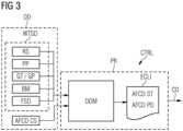
- the wind turbine which is not shown in detail, comprises a plurality of sensors, such as a sensor for rotor speed RS, a sensor for pitch position PP, a sensor for generator torque GT, a sensor for generator power GP, or one or more sensors for a respective blade moment BM.
- sensors such as a sensor for rotor speed RS, a sensor for pitch position PP, a sensor for generator torque GT, a sensor for generator power GP, or one or more sensors for a respective blade moment BM.
- the latter takes into account that usually every blade has at least two sensors at the blade root measuring the two bending moments.
- further sensors may be provided to provide further sensor data FSD.
- the totality of sensor data corresponds to wind turbine sensor data WTSD.
- the wind turbine sensor data WTSD and a control signal AFCD CS for controlling the AFCDs 11D, 12D, 14D represent operational data OD and are obtained on a regular time basis ( Figs. 2 and 3 ).
- the wind turbines standard signals WTSD are used for general control purposes of the wind turbine, for example regarding yaw angle and/or pitch angle, rotation speed of the rotor, generated power or generated torque, and so on.
- the control signal AFCD CS is used to control the AFCD 11D, 12D, 14D to modify the air flow around the rotor blade 10 in a desired manner.
- the specific position of the AFCD 11D, 12D, 14D will primarily result in different blade moments BM.
- the respective operational data OD are transferred by a suitable communication link to a controller CTRL of the wind turbine ( Fig 3 ).
- the controller CTRL comprises a processor PR implementing a trained data driven model DDM receiving the respective operational data OD as digital input and providing the estimate ECLI of the state AFCD ST and/or performance degradation AFCD PD of the AFCD 11D, 12D, 14D as a digital output.
- the state AFCD ST of the active flow control device 11D, 12D, 14D comprises an information whether the active flow control device is inactive or active and, if active, whether it is working properly (healthy) or working improperly (faulty).
- the performance degradation AFCD PD of the AFCD 11D, 12D, 14D comprises one of a plurality of categories representing the amount of performance degradation. Each category represents, for example, a bandwidth of performance or performance degradation the active flow control device 11D, 12D, 14D.
- the performance degradation AFCD PD comprises, for example, a class or a figure about how much the performance is less than expected (for example, 25%, 50%, 75%, 100%) or, if the active flow control device 11D, 12D, 14D should be inactive, but impacts the operation by 25%, 50%, 75%, 100%.
- the trained data driven model DDM may be based on a random forest classification or a regressor model being learnt beforehand by training data.
- the training process is illustrated in Fig. 2 .
- the training data comprise a plurality of datasets of operational data OD consisting of wind turbine sensor data WTSD (RS, PP, GT/GP, BM, and optionally FSD, and AFCD CS) taken by sensors of the wind turbine and provided by an AFCD controller for controlling the AFCDs 11D, 12D, 14D together with an information CLI about the state AFCD ST and/or performance degradation AFCD PD.
- the operational data OD and the predefinded classes CLI are provided in step S1 to the data driven model DDM to be used, preferably a random forest classification or a regressor model.
- the operational data OD and the predefinded classes CLI are acquired by field measurements of a real wind turbine, from computer simulations of the wind turbine model or from a combination of both cases.
- Random forest classification or regressor models are well known from the prior art and are particularly suitable for processing the operational data OD.
- the operational data OD and the classes CLI of the state AFCD ST and/or performance degradation AFCD PD are fed to the data driven model DDM (step S2).
- step S3 it is verified whether the output of the data driven model DDM with respect to the estimated state AFCD ST and/or performance degradation AFCD PD corresponds to the predefined class CLI assigned to a data set of the operational data OD. If the estimation is correct, the data driven model DDM is implemented (step S5). If the estimation in step S3 is not correct re-training of the data driven model DDM is conducted (step S4).
- an easy and straightforward method is provided in order to detect the state and/or performance of an AFCD.
- the data driven model is used which estimates the state and/or performance degradation from "standard" wind turbine signals or their statistical values.
- the data driven model output will be used to control the wind turbine to properly include the active flow control device in the overall wind turbine control strategy.
- the data driven model may be trained by unsupervised training that can be achieved without providing the information of the state and/or performance of the active flow control device. Alternatively, continuous training may be applied in the training phase.
- the data driven model may use the wind turbine sensor data to improve its training and compensate for potential variation of the wind turbine behavior, for example with respect to reduced aerodynamic performance due to component erosion, wear and tear, reduced electrical efficiency and so on.
- individuals with male, female or other gender identities are included within the term.
Landscapes
- Engineering & Computer Science (AREA)
- Mechanical Engineering (AREA)
- Sustainable Development (AREA)
- Sustainable Energy (AREA)
- Chemical & Material Sciences (AREA)
- Combustion & Propulsion (AREA)
- Life Sciences & Earth Sciences (AREA)
- General Engineering & Computer Science (AREA)
- Physics & Mathematics (AREA)
- Fluid Mechanics (AREA)
- Artificial Intelligence (AREA)
- Evolutionary Computation (AREA)
- Theoretical Computer Science (AREA)
- Wind Motors (AREA)
Priority Applications (1)
| Application Number | Priority Date | Filing Date | Title |
|---|---|---|---|
| EP22215852.9A EP4390120A1 (fr) | 2022-12-22 | 2022-12-22 | Procédé et appareil de surveillance mise en oeuvre par ordinateur d'une éolienne |
Applications Claiming Priority (1)
| Application Number | Priority Date | Filing Date | Title |
|---|---|---|---|
| EP22215852.9A EP4390120A1 (fr) | 2022-12-22 | 2022-12-22 | Procédé et appareil de surveillance mise en oeuvre par ordinateur d'une éolienne |
Publications (1)
| Publication Number | Publication Date |
|---|---|
| EP4390120A1 true EP4390120A1 (fr) | 2024-06-26 |
Family
ID=84569331
Family Applications (1)
| Application Number | Title | Priority Date | Filing Date |
|---|---|---|---|
| EP22215852.9A Pending EP4390120A1 (fr) | 2022-12-22 | 2022-12-22 | Procédé et appareil de surveillance mise en oeuvre par ordinateur d'une éolienne |
Country Status (1)
| Country | Link |
|---|---|
| EP (1) | EP4390120A1 (fr) |
Cited By (1)
| Publication number | Priority date | Publication date | Assignee | Title |
|---|---|---|---|---|
| CN120592821A (zh) * | 2025-08-07 | 2025-09-05 | 湘江实验室 | 基于多模态数据的风机健康状态检测方法、装置、设备及介质 |
Citations (2)
| Publication number | Priority date | Publication date | Assignee | Title |
|---|---|---|---|---|
| EP3667080A1 (fr) * | 2018-12-13 | 2020-06-17 | Siemens Gamesa Renewable Energy A/S | Régulation de flux de pale d'éolienne |
| EP3667082A1 (fr) * | 2018-12-13 | 2020-06-17 | Siemens Gamesa Renewable Energy A/S | Régulation de flux de pale d'éolienne |
-
2022
- 2022-12-22 EP EP22215852.9A patent/EP4390120A1/fr active Pending
Patent Citations (2)
| Publication number | Priority date | Publication date | Assignee | Title |
|---|---|---|---|---|
| EP3667080A1 (fr) * | 2018-12-13 | 2020-06-17 | Siemens Gamesa Renewable Energy A/S | Régulation de flux de pale d'éolienne |
| EP3667082A1 (fr) * | 2018-12-13 | 2020-06-17 | Siemens Gamesa Renewable Energy A/S | Régulation de flux de pale d'éolienne |
Non-Patent Citations (2)
| Title |
|---|
| KORDESTANI MOJTABA ET AL: "A New Hybrid Fault Prognosis Method for MFS Systems Based on Distributed Neural Networks and Recursive Bayesian Algorithm", IEEE SYSTEMS JOURNAL, IEEE, US, vol. 14, no. 4, 12 May 2020 (2020-05-12), pages 5407 - 5416, XP011821966, ISSN: 1932-8184, [retrieved on 20201123], DOI: 10.1109/JSYST.2020.2986162 * |
| SI YULIN ET AL: "A data-driven approach for fault detection of offshore wind turbines using random forests", IECON 2017 - 43RD ANNUAL CONFERENCE OF THE IEEE INDUSTRIAL ELECTRONICS SOCIETY, IEEE, 29 October 2017 (2017-10-29), pages 3149 - 3154, XP033280029, DOI: 10.1109/IECON.2017.8216532 * |
Cited By (1)
| Publication number | Priority date | Publication date | Assignee | Title |
|---|---|---|---|---|
| CN120592821A (zh) * | 2025-08-07 | 2025-09-05 | 湘江实验室 | 基于多模态数据的风机健康状态检测方法、装置、设备及介质 |
Similar Documents
| Publication | Publication Date | Title |
|---|---|---|
| CN110520620B (zh) | 用于在风力涡轮机叶片变桨距轴承上减小负载的方法 | |
| EP3516210B1 (fr) | Procédé de commande de déflecteurs d'air et d'angles de pas de pales d'éolienne | |
| US10830208B2 (en) | System and method for mitigating blade run-away loads in the event of a pitch system failure | |
| US20150118047A1 (en) | Wind turbine and method for determining parameters of wind turbine | |
| DK178410B1 (en) | Active control of a wind turbine blade | |
| CN106460792A (zh) | 用于风力涡轮机推力限制的系统 | |
| CN103835881B (zh) | 基于电动有效阻尼的独立变桨系统及变桨方法 | |
| EP3581795A1 (fr) | Système et procédé de commande d'éolienne pour minimiser les dommages de pales de rotor | |
| EP3608538A1 (fr) | Solutions de remotorisation basées sur des modèles pour éoliennes | |
| CN114945750B (zh) | 用于控制风力涡轮的系统和方法 | |
| CN113011994A (zh) | 风电厂的优化 | |
| WO2021249773A1 (fr) | Commande de déviation de pale de rotor à l'aide d'un ajout de pale de rotor actif | |
| EP4390120A1 (fr) | Procédé et appareil de surveillance mise en oeuvre par ordinateur d'une éolienne | |
| CN116006389A (zh) | 风力涡轮基于学习的预测性故障检测和避免的系统和方法 | |
| US9039366B2 (en) | Control of wind turbine blade lift regulating means | |
| EP3839250A1 (fr) | Procédé et appareil de surveillance mise en uvre par ordinateur pour une éolienne | |
| EP3892850B1 (fr) | Système et procédé pour atténuer les charges agissant sur une pale de rotor d'une éolienne | |
| CN113227571B (zh) | 风力涡轮机叶片流调控 | |
| JP7746558B2 (ja) | 風力タービンを制御するためのシステム及び方法 | |
| EP3623615A1 (fr) | Réaction à un événement de survitesse | |
| EP3828408A1 (fr) | Procédé et appareil de surveillance d'une éolienne mise en uvre par ordinateur | |
| US20210340957A1 (en) | Control of a wind energy installation | |
| CN102979683A (zh) | 转子叶片组件以及调整风机中转子叶片的负载特性的方法 | |
| CN115667705B (zh) | 用于响应于电网扰动的风力涡轮机操作方法 | |
| KR20250159651A (ko) | 풍력 터빈의 작동 |
Legal Events
| Date | Code | Title | Description |
|---|---|---|---|
| PUAI | Public reference made under article 153(3) epc to a published international application that has entered the european phase |
Free format text: ORIGINAL CODE: 0009012 |
|
| STAA | Information on the status of an ep patent application or granted ep patent |
Free format text: STATUS: THE APPLICATION HAS BEEN PUBLISHED |
|
| AK | Designated contracting states |
Kind code of ref document: A1 Designated state(s): AL AT BE BG CH CY CZ DE DK EE ES FI FR GB GR HR HU IE IS IT LI LT LU LV MC ME MK MT NL NO PL PT RO RS SE SI SK SM TR |
|
| STAA | Information on the status of an ep patent application or granted ep patent |
Free format text: STATUS: REQUEST FOR EXAMINATION WAS MADE |
|
| 17P | Request for examination filed |
Effective date: 20250102 |
|
| GRAP | Despatch of communication of intention to grant a patent |
Free format text: ORIGINAL CODE: EPIDOSNIGR1 |
|
| STAA | Information on the status of an ep patent application or granted ep patent |
Free format text: STATUS: GRANT OF PATENT IS INTENDED |
|
| RIC1 | Information provided on ipc code assigned before grant |
Ipc: F03D 17/00 20160101AFI20251211BHEP Ipc: F03D 7/02 20060101ALI20251211BHEP Ipc: F03D 7/04 20060101ALN20251211BHEP |
|
| INTG | Intention to grant announced |
Effective date: 20260112 |
|
| GRAS | Grant fee paid |
Free format text: ORIGINAL CODE: EPIDOSNIGR3 |
|
| GRAA | (expected) grant |
Free format text: ORIGINAL CODE: 0009210 |
|
| STAA | Information on the status of an ep patent application or granted ep patent |
Free format text: STATUS: THE PATENT HAS BEEN GRANTED |