EP4390132A1 - Appareil de distribution d'air d'admission et compresseur le comprenant - Google Patents
Appareil de distribution d'air d'admission et compresseur le comprenant Download PDFInfo
- Publication number
- EP4390132A1 EP4390132A1 EP22857534.6A EP22857534A EP4390132A1 EP 4390132 A1 EP4390132 A1 EP 4390132A1 EP 22857534 A EP22857534 A EP 22857534A EP 4390132 A1 EP4390132 A1 EP 4390132A1
- Authority
- EP
- European Patent Office
- Prior art keywords
- distribution device
- side wall
- flow
- intake
- circumferential side
- Prior art date
- Legal status (The legal status is an assumption and is not a legal conclusion. Google has not performed a legal analysis and makes no representation as to the accuracy of the status listed.)
- Pending
Links
Images







Classifications
-
- F—MECHANICAL ENGINEERING; LIGHTING; HEATING; WEAPONS; BLASTING
- F04—POSITIVE - DISPLACEMENT MACHINES FOR LIQUIDS; PUMPS FOR LIQUIDS OR ELASTIC FLUIDS
- F04C—ROTARY-PISTON, OR OSCILLATING-PISTON, POSITIVE-DISPLACEMENT MACHINES FOR LIQUIDS; ROTARY-PISTON, OR OSCILLATING-PISTON, POSITIVE-DISPLACEMENT PUMPS
- F04C29/00—Component parts, details or accessories of pumps or pumping installations, not provided for in groups F04C18/00 - F04C28/00
- F04C29/12—Arrangements for admission or discharge of the working fluid, e.g. constructional features of the inlet or outlet
-
- F—MECHANICAL ENGINEERING; LIGHTING; HEATING; WEAPONS; BLASTING
- F04—POSITIVE - DISPLACEMENT MACHINES FOR LIQUIDS; PUMPS FOR LIQUIDS OR ELASTIC FLUIDS
- F04C—ROTARY-PISTON, OR OSCILLATING-PISTON, POSITIVE-DISPLACEMENT MACHINES FOR LIQUIDS; ROTARY-PISTON, OR OSCILLATING-PISTON, POSITIVE-DISPLACEMENT PUMPS
- F04C23/00—Combinations of two or more pumps, each being of rotary-piston or oscillating-piston type, specially adapted for elastic fluids; Pumping installations specially adapted for elastic fluids; Multi-stage pumps specially adapted for elastic fluids
- F04C23/008—Hermetic pumps
-
- F—MECHANICAL ENGINEERING; LIGHTING; HEATING; WEAPONS; BLASTING
- F04—POSITIVE - DISPLACEMENT MACHINES FOR LIQUIDS; PUMPS FOR LIQUIDS OR ELASTIC FLUIDS
- F04C—ROTARY-PISTON, OR OSCILLATING-PISTON, POSITIVE-DISPLACEMENT MACHINES FOR LIQUIDS; ROTARY-PISTON, OR OSCILLATING-PISTON, POSITIVE-DISPLACEMENT PUMPS
- F04C29/00—Component parts, details or accessories of pumps or pumping installations, not provided for in groups F04C18/00 - F04C28/00
- F04C29/02—Lubrication; Lubricant separation
- F04C29/026—Lubricant separation
-
- F—MECHANICAL ENGINEERING; LIGHTING; HEATING; WEAPONS; BLASTING
- F04—POSITIVE - DISPLACEMENT MACHINES FOR LIQUIDS; PUMPS FOR LIQUIDS OR ELASTIC FLUIDS
- F04C—ROTARY-PISTON, OR OSCILLATING-PISTON, POSITIVE-DISPLACEMENT MACHINES FOR LIQUIDS; ROTARY-PISTON, OR OSCILLATING-PISTON, POSITIVE-DISPLACEMENT PUMPS
- F04C29/00—Component parts, details or accessories of pumps or pumping installations, not provided for in groups F04C18/00 - F04C28/00
- F04C29/04—Heating; Cooling; Heat insulation
- F04C29/045—Heating; Cooling; Heat insulation of the electric motor in hermetic pumps
-
- F—MECHANICAL ENGINEERING; LIGHTING; HEATING; WEAPONS; BLASTING
- F04—POSITIVE - DISPLACEMENT MACHINES FOR LIQUIDS; PUMPS FOR LIQUIDS OR ELASTIC FLUIDS
- F04C—ROTARY-PISTON, OR OSCILLATING-PISTON, POSITIVE-DISPLACEMENT MACHINES FOR LIQUIDS; ROTARY-PISTON, OR OSCILLATING-PISTON, POSITIVE-DISPLACEMENT PUMPS
- F04C18/00—Rotary-piston pumps specially adapted for elastic fluids
- F04C18/02—Rotary-piston pumps specially adapted for elastic fluids of arcuate-engagement type, i.e. with circular translatory movement of co-operating members, each member having the same number of teeth or tooth-equivalents
- F04C18/0207—Rotary-piston pumps specially adapted for elastic fluids of arcuate-engagement type, i.e. with circular translatory movement of co-operating members, each member having the same number of teeth or tooth-equivalents both members having co-operating elements in spiral form
- F04C18/0215—Rotary-piston pumps specially adapted for elastic fluids of arcuate-engagement type, i.e. with circular translatory movement of co-operating members, each member having the same number of teeth or tooth-equivalents both members having co-operating elements in spiral form where only one member is moving
Definitions
- the present disclosure relates to an intake distribution device, which is horizontally arranged along a longitudinal direction and an axial direction of the intake distribution device.
- a compressor includes a compression mechanism for compressing a working fluid, a main bearing seat for supporting the compression mechanism, a motor for driving the compression mechanism, a housing body for accommodating the compression mechanism and the motor, and an intake joint arranged on the housing body for introducing the working fluid.
- the working fluid enters the housing body of the compressor through the intake joint, flows in the housing body, and enters the compression mechanism through a suction chamber of the compression mechanism for compression.
- the compressed working fluid is discharged from the compressor.
- an object of the present application is to provide an intake distribution device, which can effectively guide the fluid to a required area so as to cool a high-temperature component in the required area, and prevent the working fluid from contacting with lubricating oil to a certain extent.
- Another object of the present application is to provide a compressor including the above intake distribution device, which can have an improved oil circulation rate and can effectively improve a working efficiency of the compressor.
- an intake distribution device includes a flow guide unit.
- the flow guide unit is configured to guide a part of a fluid entering a housing of the compressor to flow along a predetermined route.
- the flow guide unit includes a body, and an inlet channel and an outlet channel are provided in the body.
- the inlet channel is configured to introduce a part of the fluid in the housing of the compressor into the flow guide unit, and the outlet channel is configured to enable a part of the fluid to flow out in a predetermined orientation.
- the flow guide unit by providing the flow guide unit, a part of the fluid can be more accurately and effectively directed to a required area, e.g., an area where some high-temperature components need to be cooled.
- the flow guide unit can guide the fluid to flow along the predetermined route, and prevent the fluid from contacting with lubricating oil, thereby controlling the oil circulation rate.
- the intake distribution device further includes a flow dividing unit.
- the flow dividing unit is configured to divide the fluid introduced into the housing of the compressor into a first fluid portion and a second fluid portion.
- the flow dividing unit includes a base and a partition plate, and the partition plate divides the base into a first base and a second base.
- a first channel for the first fluid portion is defined by the partition plate and the first base
- a second channel for the second fluid portion is defined by the partition plate and the second base.
- the inlet channel of the flow guide unit is located downstream of the second channel so as to guide the second fluid portion to flow along the predetermined route.
- the intake distribution device can distribute the fluid properly by means of the partition plate, thereby better controlling the flow of the fluid and the oil circulation rate.
- the flow dividing unit and the flow guide unit are formed into one piece, or the flow dividing unit and the flow guide unit are separately formed.
- the base of the flow dividing unit includes a back plate, side plates extending from two sides of the back plate, and a bottom plate extending from a lower side of the back plate.
- the partition plate extends transversely to the back plate and the side plates, the second channel is defined between the partition plate and the bottom plate, and an outlet of the second channel is provided in the back plate.
- the base of the flow dividing unit is hollow cylindrical.
- the first base and the second base, separated by the partition plate, of the base each have an arc-shaped cross section.
- the first channel and the second channel have a same input end.
- An axial length of the first base extending from the input end is smaller than an axial length of the second base extending from the input end.
- the body is annular, and multiple outlet channels are arranged in a circumferential direction.
- the body includes an inner circumferential side wall and an outer circumferential side wall.
- Multiple outlet channels are defined in an annular space between the inner circumferential side wall and the outer circumferential side wall.
- the inlet channel extends through the outer circumferential side wall.
- the flow guide unit further includes a connecting portion extending radially outward from the outer circumferential side wall.
- the inlet channel extends through the connecting portion.
- the flow guide unit further includes a flange extending radially outward from the outer circumferential side wall.
- the flow guide unit further includes a protrusion extending radially inward from the inner circumferential side wall.
- the flow guide unit further includes a cylindrical cover radially outside the outer circumferential side wall.
- multiple ribs are provided between the inner circumferential side wall and the outer circumferential side wall in a circumferential direction.
- the multiple outlet channels are defined by the multiple ribs, the inner circumferential side wall and the outer circumferential side wall.
- annular bottom wall is provided between the inner circumferential side wall and the outer circumferential side wall.
- the outlet channel has a discharge opening, and the discharge opening is provided in the annular bottom wall or the outer circumferential side wall.
- a compressor including the above intake distribution device is provided.
- the compressor further includes: a housing provided thereon with an intake port at which an intake joint is mounted; a compression mechanism located in the housing and configured to compress a fluid sucked in through a suction chamber; a motor configured to drive the compression mechanism, and including a stator fixed to the housing and a rotor located radially inside the stator; and a bearing seat located between the compression mechanism and the motor, and configured to support the compression mechanism.
- the intake distribution device is arranged at the intake port to guide a part of the fluid introduced into the housing to flow above the motor.
- a partition plate of a flow dividing unit of the intake distribution device is at least partially projected in a flow region of the intake joint so as to divide the fluid introduced into the housing into a first fluid portion and a second fluid portion.
- the flow guide unit is located between the bearing seat and the motor, and is configured to guide the second fluid portion to flow over a winding of the stator.
- a discharge opening of the outlet channel of the flow guide unit is located radially outside the rotor.
- a cylindrical cover of the flow guide unit is located radially outside the outlet channel and is located radially outside the winding in the radial direction.
- the flow dividing unit is fixed to the bearing seat, the housing or the intake joint; and/or the flow guide unit is fixed to the bearing seat, the housing or the stator.
- a gap is formed between the flow dividing unit and the intake joint, and the gap is less than one fifth of a minimum inner diameter of the intake joint.
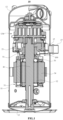
- FIG. 1 is a longitudinal sectional view of a scroll compressor 10 having an intake distribution device 100 according to an embodiment of the present disclosure.
- the scroll compressor 10 includes a substantially cylindrical housing body 11, a top cover 12 and a bottom cover 13.
- the top cover 12 and the bottom cover 13 are respectively located at two ends of the housing body 11.
- a sealing internal space is defined by the housing body 11, the top cover 12 and the bottom cover 13 which form a housing of the scroll compressor 10.
- An intake port 15 is arranged on the housing (specifically, the housing body 11 in the example shown in FIG. 1 ), and an intake joint 17 is mounted in the intake port 15, so as to introduce a low-temperature and low-pressure working fluid (for example, a refrigerant) into the closed internal space of the scroll compressor 10.
- a low-temperature and low-pressure working fluid for example, a refrigerant
- the scroll compressor 10 further includes a scroll compression mechanism CM accommodated in the housing.
- the scroll compression mechanism CM has a suction chamber.
- the low-temperature and low-pressure working fluid entering the housing is sucked into the suction chamber, and then becomes a high-temperature and high-pressure working fluid after being compressed by a series of compression chambers. Finally, the high-temperature and high-pressure working fluid is discharged from the scroll compressor 10.
- the scroll compression mechanism CM is a conventional scroll compression mechanism, so it will not be described in detail herein.
- the scroll compressor 10 further includes a motor 31 accommodated in the housing.
- the motor 31 is configured to drive the scroll compression mechanism CM.
- the motor 31 includes a stator 34 fixed to the housing (specifically, the housing body 11 in the example shown in FIG. 1 ) and a rotor 32 located radially inside the stator 34.
- the rotor 32 is fixedly mounted to a drive shaft 41, so as to drive the drive shaft 41 to rotate together, and then the drive shaft 41 drives a movable scroll member of the scroll compression mechanism CM to orbit.
- various components of the motor generate heat, especially a winding 36 on the stator 34.
- the scroll compressor 10 further includes a bearing seat 21.
- the bearing seat 21 is located between the scroll compression mechanism CM and the motor 31.
- a bearing 51 is provided between the bearing seat 21 and the drive shaft 41. Therefore, the drive shaft 41 and the scroll compression mechanism CM are rotatably supported on the bearing seat 21.
- the scroll compressor 10 further includes an intake distribution device 100.
- the intake distribution device 100 is arranged at the intake port 15, and is configured to divide the fluid introduced through the intake joint 17 into a first fluid portion and a second fluid portion in an appropriate ratio.
- the first fluid portion flows into the suction chamber of the scroll compression mechanism CM in a shortest path.
- the second fluid portion is guided to flow over the motor 31 to cool the motor 31.
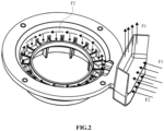
- FIG. 2 is a schematic view showing flow of gas through the intake distribution device in FIG. 1 .
- the first fluid portion F1 flows upward toward the scroll compression mechanism CM after being divided.
- the second fluid portion F2 flows radially inward toward the drive shaft 41, then flows along the annular channel, and finally flows downward toward the motor 31.
- FIGS. 3A to 3E are schematic perspective views, a plan top view, a revolved sectional view and a partially schematic mounting view of the intake distribution device 100 in FIGS. 1 and 2 respectively.
- the intake distribution device 100 includes a flow dividing unit 110 and a flow guide unit 120.
- the flow dividing unit 110 is configured to divide the introduced fluid into a first fluid portion F1 and a second fluid portion F2.
- the flow guide unit 120 is configured to direct the second fluid portion F2 to flow in a predetermined route, specifically, guide the second fluid portion F2 to flow over the winding 36 of the motor 31 in the example shown in FIG. 1 .
- the flow dividing unit 110 and the flow guide unit 120 are formed as one piece.
- the intake distribution device 100 may be formed by injection molding.
- the flow dividing unit 110 includes a base 111 and a partition plate 112.
- the base 111 of the flow dividing unit 110 includes a back plate 101, side plates 103 and 104 extending from two sides of the back plate 101, and a bottom plate 102 extending from a lower side of the back plate 101.
- the partition plate 112 extends transversely to the back plate 101 and the side plates 103 and 104, and divides the back plate 101 and the side plates 103 and 104 into an upper portion and a lower portion. Upper portions of the back plate 101 and the side plates 103 and 104 form a first base, and a first channel C1 with an open end for the first fluid portion F1 is defined by the partition plate 112 and the first base.
- Lower portions of the back plate 101 and the side plates 103 and 104 together with the bottom plate 102 form a second base, and a second channel C2 for the second fluid portion F2 is defined by the partition plate 112 and the second base.
- An outlet 106 of the second channel C2 is provided in the back plate 101.
- the flow guide unit 120 is located downstream of the second channel C2. In this way, the second fluid portion F2 can flow through the outlet 106 into the flow guide unit 120 at the downstream side.
- the partition plate 112 when the intake distribution device 100 is mounted in the scroll compressor 10, along a direction of a central axis of the intake port 15, the partition plate 112 is at least partially projected in a flow region of the intake joint 17.
- both the first channel C1 and the second channel C2 have portions overlapping with the internal flow region of the intake joint 17.
- the ratio of the first fluid portion F1 to the second fluid portion F2 can be changed accordingly. If the overlapping portion of the first channel C1 and the internal flow region of the intake joint 17 increases, the first fluid portion F 1 increases.
- the position or structure of the partition plate 112 may be designed according to the required ratio of the first fluid portion F 1 to the second fluid portion F2.
- the flow guide unit 120 is located between the bearing seat 21 and the motor 31, so as to direct the fluid above the motor 31.
- the flow guide unit includes a body 121.
- An inlet channel 150 and an outlet channel 125 are provided in the body 121.
- the inlet channel 150 is configured to be in communication with the second channel C2 to introduce the second fluid portion F2.
- the outlet channel 125 is configured to allow the second fluid portion F2 to flow out in a predetermined orientation, for example, toward the winding 36 of the motor 31 in the example shown in the figures.
- the body 121 is substantially annular, and includes an inner circumferential side wall 124 and an outer circumferential side wall 122.
- An annular flow channel is defined between the inner circumferential side wall 124 and the outer circumferential side wall 122.
- Multiple ribs 123 may be provided between the inner circumferential side wall 124 and the outer circumferential side wall 122 in a circumferential direction. In this way, multiple outlet channels 125 are defined by the inner circumferential side wall 124, the outer circumferential side wall 122 and the ribs 123.
- a connecting portion 151 may be provided between the flow dividing unit 110 and the flow guide unit 120.
- the connecting portion 151 extends radially outward from the outer circumferential side wall 122, such as to be in communication with the second channel C2.
- the inlet channel 150 extends through the connecting portion 151 and the outer circumferential side wall 122.
- the second fluid portion F2 from the second channel C2 enters the annular flow channel defined between the inner circumferential side wall 124 and the outer circumferential side wall 122 through the inlet channel 150, and is sprayed above the motor 31 through the multiple outlet channels 125 arranged in the circumferential direction so as to cool the motor 31.
- the outer circumferential side wall 122 is substantially straight and cylindrical, and the inner circumferential side wall 124 has multiple sections with different diameters, so that the size and orientation of the outlets of the outlet channels 125 can be controlled, thereby controlling the amount and orientation of the discharged second fluid portion F2.
- a discharge opening of the outlet channel 125 of the flow guide unit 120 may be located radially outside the rotor 32. In this way, the fluid discharged through the outlet channel 125 can be separated from the lubricating oil thrown from the drive shaft 41, and the fluid can be guided to the winding 36 of the stator 34 so as to cool the winding 36.
- the flow guide unit 120 may further include a flange 131 extending radially outward from the outer circumferential side wall 122.
- a hole 132 may be provided in the flange 131 to receive fasteners, so as to mount or fix the flow guide unit 120.
- a threaded hole 22 is provided in the bearing seat 21.
- a screw 90 may be inserted into the hole 132 of the flow guide unit 120 and threadedly engaged with the threaded hole 22 of the bearing seat 21, thereby fixedly mounting the flow guide unit 120 (the intake distribution device 100) to the bearing seat 21.
- the intake distribution device 100 is mounted to the bearing seat 21, it is advantageous that a gap is formed between the flow dividing unit 110 of the intake distribution device 100 and the intake joint 17 along the direction of the central axis of the intake port 15, so as to avoid mounting interference.
- the gap is less than one fifth of a minimum inner diameter of the intake joint 17. In this way, not only mounting interference can be avoided, but also excessive fluid can be prevented from flowing through the radial outer side of the motor 31 through the gap to disturb or carry more lubricating oil.
- a temperature of the motor is 310F (Fahrenheit).
- the scroll compressor 10 according to the present disclosure can reduce the temperature of the motor to 220F when it operates at the same low rotation speed.
- the scroll compressor according to the present disclosure can significantly improve the working efficiency of the scroll compressor, for example, the IEER (comprehensive energy efficiency ratio) can reach 29.9.
- an oil circulation rate of the scroll compressor according to the present disclosure can be reduced to 3.0% or less.
- FIGS. 4A to 4D various examples of outlet channels of the intake distribution device are shown in FIGS. 4A to 4D .
- both the inner circumferential side wall 124 and the outer circumferential side wall 122 are in the shape of straight cylinders.
- An annular bottom wall 171 is provided between the inner circumferential side wall 124 and the outer circumferential side wall 122, and the ribs 123 in FIGS. 3A to 3D are omitted.
- Multiple discharge openings 125a are provided in the annular bottom wall 171. The multiple discharge openings 125a may be uniformly arranged in the circumferential direction and may have the same size and shape.
- the example in FIG. 4B is different from the example in FIG. 4A in that, the multiple discharge openings 125a are provided in the outer circumferential side wall 122, rather than in the annular bottom wall 171.
- the example in FIG. 4C is similar to the example in FIGS. 3A to 3D .
- the multiple outlet channels 125c are defined by the inner circumferential side wall 124, the outer circumferential side wall 122, and the ribs 123 arranged between the inner circumferential side wall 124 and the outer circumferential side wall 122.
- the example in FIG. 4C is different from the example in FIGS. 3A to 3D in that, both the inner circumferential side wall 124 and the outer circumferential side wall 122 are in the shape of straight cylinders, so that the outlet channels 125c have a substantially constant flow area, and the fluid flows downward from the outlet channels 125c.
- the example in FIG. 4D is different from the example in FIG. 4A in that, the discharge openings 125d1 to 125d4 of the outlet channels have different discharge flow areas.
- the discharge openings 125d1 to 125d4 are away from the connecting portion 151 (i.e., the inlet channel 150) in a listed sequence.
- the discharge opening 125d1 is close to the inlet channel 150.
- the discharge opening 125d2 is farther away from the inlet channel 150 than the discharge opening 125d1.
- the discharge opening 125d3 is farther away from the inlet channel 150 than the discharge opening 125d2.
- the discharge opening 125d4 is opposite to the discharge opening 125d1 and is farthest away from the inlet channel 150.
- the discharge flow areas of the discharge openings 125d1 to 125d4 gradually increase. In other words, the closer the outlet channel is to the inlet channel 150 in the circumferential direction, the smaller the discharge flow area is.
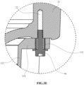
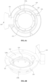
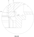
- FIGS. 5A to 5E are a schematic perspective view, a plan top view, a schematic sectional view taken along line G-G in FIG. 5B , a partially schematic enlarged view, and a partially schematic mounting view of an intake distribution device 200 according to another embodiment of the present disclosure respectively.
- the flow guide unit 220 includes a protrusion 241 (or may be referred to as a hook portion) extending radially inward from the inner circumferential side wall 224. Multiple protrusions 241 may be uniformly distributed in the circumferential direction.
- the outer circumferential side wall 222 of the flow guide unit 220 is not provided with the flange as shown in FIGS. 3A to 3C ,
- recesses 24 are provided on the bearing seat 24 to receive the protrusions 241.
- the intake distribution device 200 is mounted, the intake distribution device 200 is pushed toward the bearing seat 21.
- the protrusions 241 are engaged in the recesses 24, the intake distribution device 200 is mounted in place.
- the flow dividing unit 210, the connecting portion 251, the ribs 223 and the outlet channels 225 shown in FIGS. 5A to 5E are similar to the corresponding parts in FIGS. 3A to 3E , so detailed descriptions are omitted herein.
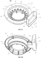
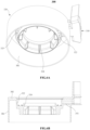
- FIGS. 6A to 6C are a schematic perspective view, a longitudinal sectional view and a schematic mounting view of an intake distribution device 300 according to another embodiment of the present disclosure respectively.
- the intake distribution device 300 in FIGS. 6A to 6C is different from the intake distribution device 100 in FIGS. 3A to 3E in that, the flow guide unit 320 further includes a cover 381 extending downward from the flange 382.
- the cover 381 is substantially cylindrical.
- the cover 381 is located radially outside the outer circumferential side wall 322, surrounds the outlet channels 325, and is located radially outside the winding 36, so as to prevent the fluid discharged from the outlet channels 325 between the outer circumferential side wall 322 and the inner circumferential side wall 324 from flowing to the region radially outside the motor 31.
- the cover 381 may be fixed to the stator 34, thereby mounting the intake distribution device 300.
- the flow dividing unit 310, the connecting portion 351, and the outlet channels 325 shown in FIGS. 6A to 6C are similar to the corresponding parts in FIGS. 3A to 3E , so detailed descriptions are omitted herein.
- FIG. 7A is a longitudinal sectional view of a scroll compressor having an intake distribution device 400 according to another embodiment of the present disclosure.
- the intake distribution device 400 in FIG. 7A is different from the intake distribution devices 100 to 300 in that, the flow dividing unit 410 and the flow guide unit 420 have split structures.
- the flow dividing unit 410 and the flow guide unit 420 are separately formed and mounted at different parts of the scroll compressor.
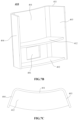
- FIGS. 7B and 7C are a schematic perspective view and a plan top view of the flow dividing unit 410 of the intake distribution device 400 in FIG. 7A .
- the flow dividing unit 410 in FIGS. 7B and 7C is similar to the flow dividing unit 110 in FIGS. 3A to 3D .
- the flow dividing unit 410 includes a base 411 and a partition plate 412.
- the base 411 of the flow dividing unit 410 includes a back plate 401, side plates 403 and 404 extending from two sides of the back plate 401, and a bottom plate 402 extending from a lower side of the back plate 401.
- the partition plate 412 extends transversely to the back plate 401 and the side plates 403 and 404, and divides the back plate 401 and the side plates 403 and 404 into an upper portion and a lower portion, thereby forming a first channel and a second channel.
- An outlet 406 of the second channel is defined on the back plate 401.
- the flow dividing unit 410 in FIGS. 7B and 7C is different from the flow dividing unit 110 in FIGS. 3A to 3D in that, the back plate 401 is arc-shaped and an end surface of the partition plate 412 is correspondingly arc-shaped. It should be understood that the structure of the flow dividing unit can be changed as required and should not be limited to the specific examples shown in the figures.
- FIGS. 7D to 7F are a schematic perspective view, a plan top view and a schematic revolved sectional view, taken along line A-A in FIG. 7E , of the flow guide unit 420 of the intake distribution device 400 in FIG. 7A respectively.
- the flow guide unit 420 is similar to the flow guide unit 320 in FIGS. 6A to 6C .
- the flow guide unit 420 has a cover 481 extending downward from the flange 482.
- the cover 481 is located radially outside the outer circumferential side wall 422.
- the inner circumferential side wall 424 is located radially inside the outer circumferential side wall 422 and, together with the outer circumferential side wall 422, defines an outlet channel 425 for discharging the fluid.
- the flow guide unit 420 is different from the flow guide unit 320 in that, the structure of the inlet channel 450 is different.
- the inlet channel 450 is in the form of a recess with an upward opening, rather than a closed channel.
- the inlet channel 450 is defined by both the flange 482 and the bearing seat 21. Therefore, the structure of the inlet channel can be changed according to the actual situation, and is not necessarily limited to the specific examples shown in the figures.
- the intake distribution device may only have the flow guide unit.
- a part of the fluid entering the housing of the compressor is effectively guided by the flow guide unit to flow above the motor, so as to cool the motor.
- the part of the fluid at the intake port is directly guided by the flow guide unit to flow over the motor, the part of the fluid can be prevented from contacting with the lubricating oil.
- a part of the fluid entering the housing of the compressor generally flows downward along the housing, contacts with the lubricating oil in an oil pool at the bottom of the housing, and then carries more lubricating oil to the compression mechanism. Therefore, the lubricating oil in the conventional compressor gradually decreases, and more lubricating oil enters other components outside the compressor, thus affecting the efficiency of other components and reducing the efficiency of the whole compressor system.
- FIG. 8A is a longitudinal sectional view of a scroll compressor having an intake distribution device 500 according to another embodiment of the present disclosure.
- the intake distribution device 500 in FIG. 8A is similar to the intake distribution device 400 in FIG. 7A in that, the intake distribution device 500 also has a flow dividing unit 510 and a flow guide unit 520 with split structures.
- the structure of the flow guide unit 520 is similar to the structure of the flow guide unit 420, which is not described in detail herein.
- FIGS. 8B and 8C are a schematic perspective view and a schematic side view of the flow dividing unit 510 of the intake distribution device 500 in FIG. 8A respectively.
- the flow dividing unit 510 has a substantially hollow cylindrical base 511.
- the partition plate 512 is located in a hollow space of the base 511, and divides the base 511 into an upper arc-shaped base 501 (a first base with an arc-shaped cross section) and a lower arc-shaped base 502 (a second base with an arc-shaped cross section).
- a first channel C1 is defined by the partition plate 512 and the upper arc-shaped base 501 (the first base).
- a second channel C2 is defined by the partition plate 512 and the lower arc-shaped base 502 (the second base).
- the first channel C1 and the second channel C2 have a same input end 515, but have different output ends 516 and 517.
- An axial length of the upper arc-shaped base 501 (the first base) extending from the input end 515 to the output end 516 is smaller than an axial length of the lower arc-shaped base 502 (the second base) extending from the input end 515 to the output end 517. Therefore, the second channel C2 is longer than the first channel C1, which facilitates the introduction of the fluid into the flow guide unit 520.
- the flow dividing unit 510 is fixed in the intake joint 17.
- the flow dividing unit 510 may be fixed to the bearing seat 21 or the housing body 11, and is not necessarily limited to the specific example shown in FIG. 7A .
- the flow guide unit 520 may be fixed to the bearing seat 21, the stator 34 or the housing body 11, as long as it can achieve the functions described herein.
- the scroll compressor is taken as an example for description herein. However, it should be understood that the present disclosure can be applied to any other suitable types of compressor.
Landscapes
- Engineering & Computer Science (AREA)
- Mechanical Engineering (AREA)
- General Engineering & Computer Science (AREA)
- Applications Or Details Of Rotary Compressors (AREA)
- Rotary Pumps (AREA)
Applications Claiming Priority (3)
| Application Number | Priority Date | Filing Date | Title |
|---|---|---|---|
| CN202121917161.9U CN215521276U (zh) | 2021-08-16 | 2021-08-16 | 进气分配装置及包括该进气分配装置的压缩机 |
| CN202110937279.6A CN115704392A (zh) | 2021-08-16 | 2021-08-16 | 进气分配装置及包括该进气分配装置的压缩机 |
| PCT/CN2022/108209 WO2023020221A1 (fr) | 2021-08-16 | 2022-07-27 | Appareil de distribution d'air d'admission et compresseur le comprenant |
Publications (2)
| Publication Number | Publication Date |
|---|---|
| EP4390132A1 true EP4390132A1 (fr) | 2024-06-26 |
| EP4390132A4 EP4390132A4 (fr) | 2025-08-20 |
Family
ID=85239472
Family Applications (1)
| Application Number | Title | Priority Date | Filing Date |
|---|---|---|---|
| EP22857534.6A Pending EP4390132A4 (fr) | 2021-08-16 | 2022-07-27 | Appareil de distribution d'air d'admission et compresseur le comprenant |
Country Status (2)
| Country | Link |
|---|---|
| EP (1) | EP4390132A4 (fr) |
| WO (1) | WO2023020221A1 (fr) |
Family Cites Families (10)
| Publication number | Priority date | Publication date | Assignee | Title |
|---|---|---|---|---|
| JPH0765578B2 (ja) * | 1988-12-07 | 1995-07-19 | 三菱電機株式会社 | スクロール圧縮機 |
| DE19726943C2 (de) * | 1997-06-25 | 2000-03-23 | Bitzer Kuehlmaschinenbau Gmbh | Kältemittelkompressor |
| FR2808308B1 (fr) * | 2000-04-27 | 2002-06-28 | Danfoss Maneurop S A | Compresseur a spirale equipe d'un deflecteur en regard de l'orifice d'aspiration menage dans son enveloppe |
| WO2007114582A1 (fr) * | 2006-04-06 | 2007-10-11 | Lg Electronics Inc. | Dispositif anti-refoulement pour compresseur |
| US8814537B2 (en) * | 2011-09-30 | 2014-08-26 | Emerson Climate Technologies, Inc. | Direct-suction compressor |
| JP5429319B2 (ja) * | 2012-03-30 | 2014-02-26 | ダイキン工業株式会社 | 圧縮機 |
| CN111441951B (zh) * | 2019-01-17 | 2024-07-26 | 谷轮环境科技(苏州)有限公司 | 压缩机 |
| CN209370076U (zh) * | 2019-01-17 | 2019-09-10 | 艾默生环境优化技术(苏州)有限公司 | 压缩机 |
| US11767838B2 (en) * | 2019-06-14 | 2023-09-26 | Copeland Lp | Compressor having suction fitting |
| CN215521276U (zh) * | 2021-08-16 | 2022-01-14 | 艾默生环境优化技术(苏州)有限公司 | 进气分配装置及包括该进气分配装置的压缩机 |
-
2022
- 2022-07-27 WO PCT/CN2022/108209 patent/WO2023020221A1/fr not_active Ceased
- 2022-07-27 EP EP22857534.6A patent/EP4390132A4/fr active Pending
Also Published As
| Publication number | Publication date |
|---|---|
| WO2023020221A1 (fr) | 2023-02-23 |
| EP4390132A4 (fr) | 2025-08-20 |
Similar Documents
| Publication | Publication Date | Title |
|---|---|---|
| CN112483388B (zh) | 共旋转式压缩机 | |
| CN107806411B (zh) | 压缩机 | |
| US20190203709A1 (en) | Motor-operated compressor | |
| US9651044B2 (en) | Electric compressor | |
| US11286930B2 (en) | Scroll compressor having recessed outer fixed scroll wall | |
| US11286944B2 (en) | Centrifugal compressor and method for manufacturing centrifugal compressor | |
| KR19990044128A (ko) | 스크롤 압축기 | |
| CN215521276U (zh) | 进气分配装置及包括该进气分配装置的压缩机 | |
| EP4390132A1 (fr) | Appareil de distribution d'air d'admission et compresseur le comprenant | |
| US10634142B2 (en) | Compressor oil separation and assembly method | |
| US11565207B2 (en) | Oil separator | |
| EP3608543A1 (fr) | Compresseur à vis | |
| CN209523874U (zh) | 低压壳体双缸卧式旋转压缩机及具有其的制冷循环装置 | |
| EP4067657A2 (fr) | Compresseur à spirale et climatiseur le comprenant | |
| EP3572672B1 (fr) | Compresseur et système à cycle de réfrigération | |
| US11125233B2 (en) | Compressor having oil allocation member | |
| CN210135087U (zh) | 具有油配给构件的压缩机 | |
| CN115704392A (zh) | 进气分配装置及包括该进气分配装置的压缩机 | |
| EP4170172B1 (fr) | Compresseur à spirale | |
| EP4621239A1 (fr) | Refroidissement de moteur dans des compresseurs à vis | |
| KR102314323B1 (ko) | 엔진 구동 장치 | |
| CN111749899B (zh) | 具有油配给构件的压缩机 | |
| CN118499247A (zh) | 压缩机机架、压缩机及空调 | |
| JP2024537007A (ja) | スクロール圧縮機 | |
| CN118670037A (zh) | 一种气液分离器及压缩机 |
Legal Events
| Date | Code | Title | Description |
|---|---|---|---|
| STAA | Information on the status of an ep patent application or granted ep patent |
Free format text: STATUS: THE INTERNATIONAL PUBLICATION HAS BEEN MADE |
|
| PUAI | Public reference made under article 153(3) epc to a published international application that has entered the european phase |
Free format text: ORIGINAL CODE: 0009012 |
|
| STAA | Information on the status of an ep patent application or granted ep patent |
Free format text: STATUS: REQUEST FOR EXAMINATION WAS MADE |
|
| 17P | Request for examination filed |
Effective date: 20240312 |
|
| AK | Designated contracting states |
Kind code of ref document: A1 Designated state(s): AL AT BE BG CH CY CZ DE DK EE ES FI FR GB GR HR HU IE IS IT LI LT LU LV MC MK MT NL NO PL PT RO RS SE SI SK SM TR |
|
| DAV | Request for validation of the european patent (deleted) | ||
| DAX | Request for extension of the european patent (deleted) | ||
| A4 | Supplementary search report drawn up and despatched |
Effective date: 20250721 |
|
| RIC1 | Information provided on ipc code assigned before grant |
Ipc: F04C 29/12 20060101AFI20250715BHEP Ipc: F04C 23/00 20060101ALI20250715BHEP Ipc: F04C 29/02 20060101ALI20250715BHEP Ipc: F04C 29/04 20060101ALI20250715BHEP Ipc: F04C 18/02 20060101ALI20250715BHEP |