EP4390135B1 - Roue à aubes pour une pompe et pompe comprenant une telle roue à aubes - Google Patents
Roue à aubes pour une pompe et pompe comprenant une telle roue à aubes Download PDFInfo
- Publication number
- EP4390135B1 EP4390135B1 EP22214788.6A EP22214788A EP4390135B1 EP 4390135 B1 EP4390135 B1 EP 4390135B1 EP 22214788 A EP22214788 A EP 22214788A EP 4390135 B1 EP4390135 B1 EP 4390135B1
- Authority
- EP
- European Patent Office
- Prior art keywords
- impeller
- seal member
- pump
- seat
- lower seal
- Prior art date
- Legal status (The legal status is an assumption and is not a legal conclusion. Google has not performed a legal analysis and makes no representation as to the accuracy of the status listed.)
- Active
Links
Images

Classifications
-
- F—MECHANICAL ENGINEERING; LIGHTING; HEATING; WEAPONS; BLASTING
- F04—POSITIVE - DISPLACEMENT MACHINES FOR LIQUIDS; PUMPS FOR LIQUIDS OR ELASTIC FLUIDS
- F04D—NON-POSITIVE-DISPLACEMENT PUMPS
- F04D1/00—Radial-flow pumps, e.g. centrifugal pumps; Helico-centrifugal pumps
- F04D1/06—Multi-stage pumps
- F04D1/063—Multi-stage pumps of the vertically split casing type
-
- F—MECHANICAL ENGINEERING; LIGHTING; HEATING; WEAPONS; BLASTING
- F04—POSITIVE - DISPLACEMENT MACHINES FOR LIQUIDS; PUMPS FOR LIQUIDS OR ELASTIC FLUIDS
- F04D—NON-POSITIVE-DISPLACEMENT PUMPS
- F04D13/00—Pumping installations or systems
- F04D13/02—Units comprising pumps and their driving means
- F04D13/06—Units comprising pumps and their driving means the pump being electrically driven
- F04D13/08—Units comprising pumps and their driving means the pump being electrically driven for submerged use
-
- F—MECHANICAL ENGINEERING; LIGHTING; HEATING; WEAPONS; BLASTING
- F04—POSITIVE - DISPLACEMENT MACHINES FOR LIQUIDS; PUMPS FOR LIQUIDS OR ELASTIC FLUIDS
- F04D—NON-POSITIVE-DISPLACEMENT PUMPS
- F04D29/00—Details, component parts, or accessories
- F04D29/08—Sealings
- F04D29/16—Sealings between pressure and suction sides
- F04D29/165—Sealings between pressure and suction sides especially adapted for liquid pumps
- F04D29/167—Sealings between pressure and suction sides especially adapted for liquid pumps of a centrifugal flow wheel
-
- F—MECHANICAL ENGINEERING; LIGHTING; HEATING; WEAPONS; BLASTING
- F04—POSITIVE - DISPLACEMENT MACHINES FOR LIQUIDS; PUMPS FOR LIQUIDS OR ELASTIC FLUIDS
- F04D—NON-POSITIVE-DISPLACEMENT PUMPS
- F04D29/00—Details, component parts, or accessories
- F04D29/18—Rotors
- F04D29/22—Rotors specially for centrifugal pumps
Definitions
- the present invention relates generally to the field of pumps configured to pump liquid comprising solid/abrasive matter. Further, the present invention relates specifically to the field of pumps such as sewage/wastewater pumps, dewatering pumps and drainage pumps especially configured for pumping liquid comprising solid matter, such as sand and stone material.
- the pumped liquid is for instance wastewater, drilling water in mining/tunneling applications, surface water on construction sites, etc. i.e. transport and dewatering applications.
- the present invention relates specifically to an impeller suitable for said pumps and applications, and relates also to a pump comprising such an impeller.
- the inventive pump may be wet installed and/or dry installed, and may be of submergible type in both installations.
- the present invention relates to an impeller comprising a hub, an upper cover disc connected to the hub, a lower cover disc and at least one vane extending between and connecting the upper cover disc and the lower cover disc, wherein the impeller comprises a lower seal member that is located in a circumferential lower seat of the lower cover disc.
- each step/lift may for instance be in the range 25-50 meters in the vertical direction, and the length of the outlet conduit, i.e. the transport distance, in each step/lift may for instance be in the range 100-300 meters.
- the pump stations for sewage/wastewater handle liquid comprising abrasive matter, especially pump stations also handling surface water.
- the pumped media is very abrasive and comprises sand, stones, etc. and applications wherein high head/pressure are required.
- the location of the impeller side of the gap i.e. the location of the impellers
- the location of the stationary side of the gap i.e. the location of the diffusers
- the housing of the hydraulic unit that is connected to the housing of the drive unit.
- a known way to try to provide small gaps is to have a lining of resilient material at the stationary parts, whereby some contact is allowed between the rotating part and the stationary part without entailing wear and risk for damages to the components.
- the lining is not as resistive to wear as metal, and the abrasive matter will inevitably provide wear to the lining.
- the site manager i.e. the process at the working site, requires a constant low liquid level and therefor the drainage pump is in constant operation even though there is only little water/liquid available in the cavity/basins.
- the water can be constituted by ground water leakage, rainwater, and especially process water from drilling, reducing dust, etc. If the water is not removed the production will be negatively affected, which cannot be accepted.
- the water is pumped/transported by means of dewatering/drainage pumps.
- the drainage pumps are in constant operation, irrespective of water being pumped or not. If the stationary parts and the rotating impeller comes in contact with each other at the gap when no media is pumped or present in the gap, the components are more susceptible for damage/wear. Due to the long tolerance chains and the risk of damage, the gaps of the prior art pumps are wider then optimal considered from a back flow point of view.
- a face seal arrangement comprising a wear ring or seal member connected to the impeller, wherein the seal member is manufactured from a harder material than the impeller.
- the seal member is glued to the seat of the impeller in order to secure that the seal member does not disengage from the impeller.
- a known impeller having a lower seal member is shown for example in document CN 203 717 362 U .
- the present invention aims at obviating the aforementioned disadvantages and failings of previously known impellers and pumps, and at providing an improved impeller and pump.
- a primary object of the present invention is to provide an improved impeller and pump of the initially defined type that comprises a construction that makes it possible to have small gaps between the stationary parts and the rotating impellers of the pump by having an impeller that is less susceptible to wear, and thereby less back flow and retained efficiency.
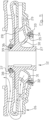
- the lower seat has an envelope surface, wherein the inner diameter of the lower seal member is greater than the diameter of the envelope surface of the lower seat, and that the impeller comprises a retainer ring that is in press fit connection with the envelope surface of the lower seat, wherein the retainer ring is configured to retain the lower seal member in the lower seat.
- the present invention is based on the insight that when using of a lower seal member, that is less sensitive to wear, it is of outermost importance that the lower seal member is fixated to the impeller. Should the lower seal member become loose/break and disengage the impeller, the entire pump risk to become damaged.
- the inner diameter of the lower seal member has to be greater than the diameter of the envelope surface of the lower seat. Should one try to have a press fit engagement between the lower seat and the lower seal member, the latter will crack/break upon mounting or when subject to already minor external force.
- the hard/brittle lower seal member is designed to manage wear but has less resistibility to tensile forces. It is no solution to manufacture the entire impeller of the same material as the lower seal member, since such impeller is much too expensive and also more prone to breakage. Thereto it is a wide aim within all manufacturing/mounting not to use glue/adhesive.
- Glue/adhesive is messy to handle, requires time to cure and requires safety measures for the work environment, which entails longer and more expensive mounting.
- the inventors have solved the necessity to securely fixate the lower seal member in the lower seat of the impeller without exerting the lower seal member for the risk of cracking/breaking and without the use of glue, by utilizing a retainer ring that is in press fit engagement with the lower seat, wherein the retainer ring is made of a material not prune to crack/break when exposed to tensile force.
- a harder and more wear resistant lower seal member may be utilized, resulting in a possibility to have a small gap and less wear, and thereby less back flow and longer service interval may be applied.
- a resilient member is located between and separates the lower seal member and the lower seat in the radial direction. Thereby the lower seal member is secured in a concentric relationship with the lower seat without the risk of having excessive tensile force acting on the lower seal member, at the same time as the resilient member will assist in securing corotation between the lower seal member and the impeller.
- the outer diameter of the retainer ring is smaller than the outer diameter of the lower seal member. Therefore the retainer ring will not risk to engage the seal member of the stationary part of the pump during operation.
- the impeller comprises an upper seal member connected to at least one of the hub and the upper cover disc of the impeller.
- the present invention relates specifically to the field of submergible pumps especially configured for pumping liquid comprising abrasive/solid matter, such as water comprising sand and stone material.
- the submergible pumps are especially wastewater pumps and drainage/dewatering pumps.
- the present invention relates specifically to an impeller suitable for such pumps and such applications, and to a pump comprising such an impeller.
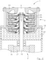
- FIG. 1 disclosing a schematic illustration of cross-sectional side view of a pump, generally designated 1.
- the general structural elements of a pump 1 will be described with reference to figure 1 .
- the pump 1 comprises two major parts, i.e. a drive unit, generally designated 2, and a hydraulic unit, generally designated 3.
- the hydraulic unit 3 of the pump 1 comprises an inlet 4, an outlet 5 and a volute 6 located intermediate said inlet 4 and said outlet 5, i.e. the volute 6 is located downstream the inlet 4 and upstream the outlet 5.
- the volute 6 is partly delimited by an impeller seat, generally designated 7, that at least partly encloses the inlet 4 and by a housing 8.
- the impeller seat 7 is stationary and connected to the housing 8.
- the pump 1 also comprises an intermediate wall structure 9 separating the hydraulic unit 3 from the drive unit 2 of the pump 1 in a liquid tight manner.
- the intermediate wall structure 9 may also comprise a liquid seal chamber 10 or the like sealing arrangement between the volute 6 of the hydraulic unit 3 and a motor compartment 11 of the drive unit 2.
- Said volute 6 is also known as pump chamber and said impeller seat 7 is also known as suction cover, wear plate, inlet insert/plate, diffuser.
- the inlet 4 is an axial inlet and the outlet 5 is a radial outlet.
- the outlet 5 of the hydraulic unit 3 also constitutes the outlet of the pump 1 (as disclosed in figure 1 ) and in other applications the outlet 5 of the hydraulic unit 3 is connected to a separate outlet of the pump 1, e.g. via a cooling jacket volume.
- the outlet of the pump 1 is configured to be connected to an outlet conduit (not shown).
- the pump 1 comprises an impeller, generally designated 12, wherein the impeller 12 is located in the volute 6, i.e. the hydraulic unit 3 of the pump 1 comprises an impeller 12.
- the impeller 12 is a channel impeller having so-called closed channels.
- the hydraulic unit 3 of the pump may comprise an inlet strainer having perforations or holes, wherein the inlet strainer is configured to prevent larger objects from reaching the inlet 4 and the volute 6. Such larger objects may otherwise jam or clog the impeller 12.
- all inlets of the pressure stages are configured as axial inlets and all outlets of the pressure stages are configured as axial outlets.
- the outlet 5 of the pump 1 is configured as an axial outlet in the disclosed embodiment, but it shall be realized that the outlet 5 may be configured as a radial outlet.
- the present invention is based on a new and improved impeller 12, that is configured to be used in pumps 1 pumping abrasive media, for instance water or wastewater/sewage comprising sand and stones.
- Impellers 12 wear quite fast in such installations due to the solid/abrasive matter in the pumped liquid and conventionally need to be replaced every 7 weeks in rough conditions because of accelerating decrease in efficiency of the pump 1 when the impeller 12 wear.
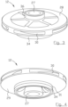
- the impeller 12 comprises a hub 27, an upper cover disc/plate 28 connected to the centrally located hub 27, a lower cover disc/plate 29 and at least one vane 30 extending between and connecting the upper cover disc 28 and the lower cover disc 29.
- the impeller 12 preferably comprises a plurality of vanes/blades 30 that are equidistantly located around the hub 27.
- the vane/vanes 30 are preferably spirally swept from an inner leading edge to an outer trailing edge, i.e. in the direction from the hub 27 towards the periphery of the impeller 12, in a direction opposite the direction of rotation of the impeller 12 during normal (liquid pumping) operation of the pump 1.
Landscapes
- Engineering & Computer Science (AREA)
- Mechanical Engineering (AREA)
- General Engineering & Computer Science (AREA)
- Structures Of Non-Positive Displacement Pumps (AREA)
Claims (13)
- Turbine (12) pour une pompe (1), la turbine (12) comprenant un moyeu (27), un disque de recouvrement supérieur (28) relié au moyeu (27), un disque de recouvrement inférieur (29) et au moins une aube (30) s'étendant entre et reliant le disque de recouvrement supérieur (28) et le disque de recouvrement inférieur (29), dans laquelle la turbine (12) comprend un organe d'étanchéité inférieur (31) qui est situé dans un siège inférieur circonférentiel (32) du disque de recouvrement inférieur (29), caractérisée en ce que le siège inférieur (32) présente une surface d'enveloppe, dans laquelle le diamètre intérieur de l'organe d'étanchéité inférieur (31) est supérieur au diamètre de la surface d'enveloppe du siège inférieur (32), et en ce que la turbine (12) comprend une bague de retenue (34) qui est en liaison par ajustement avec serrage avec la surface d'enveloppe du siège inférieur (32), dans laquelle la bague de retenue (34) est configurée pour retenir l'organe d'étanchéité inférieur (31) dans le siège inférieur (32).
- Turbine (12) selon la revendication 1, dans laquelle un organe élastique (35) est situé entre et sépare l'organe d'étanchéité inférieur (31) et le siège inférieur (32) dans la direction radiale.
- Turbine (12) selon la revendication 2, dans laquelle l'organe élastique (35) est constitué d'un joint torique en caoutchouc.
- Turbine (12) selon la revendication 2 ou 3, dans laquelle la bague de retenue (34) vient en butée contre l'organe élastique (35) et l'organe d'étanchéité inférieur (31).
- Turbine (12) selon l'une quelconque des revendications précédentes, dans laquelle le diamètre extérieur de la bague de retenue (35) est inférieur au diamètre extérieur de l'organe d'étanchéité inférieur (31).
- Turbine (12) selon l'une quelconque des revendications précédentes, dans laquelle la turbine (12) comprend un organe d'étanchéité supérieur (36) relié à au moins l'un du moyeu (27) et du disque de recouvrement supérieur (28) de la turbine (12).
- Turbine (12) selon la revendication 6, dans laquelle l'organe d'étanchéité supérieur (36) est situé dans un siège supérieur circonférentiel (37) ayant une surface d'enveloppe, dans laquelle le diamètre intérieur de l'organe d'étanchéité supérieur (36) est supérieur au diamètre de la surface d'enveloppe du siège supérieur (37).
- Turbine (12) selon la revendication 7, dans laquelle un organe élastique (39) est situé entre et sépare l'organe d'étanchéité supérieur (36) et le siège supérieur (37) dans la direction radiale.
- Turbine (12) selon la revendication 8, dans laquelle l'organe élastique (39) est constitué d'un joint torique en caoutchouc.
- Turbine (12) selon l'une quelconque des revendications précédentes, dans laquelle l'organe d'étanchéité inférieur (31) comprend du carbure cémenté.
- Turbine (12) selon l'une quelconque des revendications précédentes, dans laquelle la bague de retenue (34) est en acier inoxydable duplex.
- Pompe (1) configurée pour pomper un liquide comprenant une matière abrasive, la pompe (1) comprenant une unité d'entraînement (2) ayant un moteur électrique (13) et un arbre d'entraînement (15), et une unité hydraulique (3) ayant une entrée (4) et une sortie (5) et au moins une turbine (12) reliée à l'arbre d'entraînement (15) de l'unité d'entraînement (2), caractérisée en ce que l'au moins une turbine (12) est constituée d'une turbine (12) selon l'une quelconque des revendications 1 à 11.
- Pompe (1) selon la revendication 12, dans laquelle la pompe est constituée d'une pompe multicellulaire submersible ayant une pluralité d'étages de pression, dans laquelle chaque étage de pression comprend une turbine (12) selon l'une quelconque des revendications 1 à 11.
Priority Applications (7)
| Application Number | Priority Date | Filing Date | Title |
|---|---|---|---|
| ES22214788T ES3035964T3 (en) | 2022-12-20 | 2022-12-20 | Impeller for a pump and a pump comprising such an impeller |
| EP22214788.6A EP4390135B1 (fr) | 2022-12-20 | 2022-12-20 | Roue à aubes pour une pompe et pompe comprenant une telle roue à aubes |
| AU2023412012A AU2023412012A1 (en) | 2022-12-20 | 2023-12-11 | Impeller for a pump and a pump comprising such an impeller |
| PCT/EP2023/085084 WO2024132630A1 (fr) | 2022-12-20 | 2023-12-11 | Roue à aubes pour une pompe et pompe comprenant une telle roue à aubes |
| CN202380084050.XA CN120322621A (zh) | 2022-12-20 | 2023-12-11 | 用于泵的叶轮以及包括这种叶轮的泵 |
| CL2025001673A CL2025001673A1 (es) | 2022-12-20 | 2025-06-05 | Impulsor para bomba y bomba que comprende tal impulsor. |
| MX2025006630A MX2025006630A (es) | 2022-12-20 | 2025-06-06 | Impulsor para bomba y bomba que comprende tal impulsor |
Applications Claiming Priority (1)
| Application Number | Priority Date | Filing Date | Title |
|---|---|---|---|
| EP22214788.6A EP4390135B1 (fr) | 2022-12-20 | 2022-12-20 | Roue à aubes pour une pompe et pompe comprenant une telle roue à aubes |
Publications (3)
| Publication Number | Publication Date |
|---|---|
| EP4390135A1 EP4390135A1 (fr) | 2024-06-26 |
| EP4390135C0 EP4390135C0 (fr) | 2025-07-02 |
| EP4390135B1 true EP4390135B1 (fr) | 2025-07-02 |
Family
ID=84541546
Family Applications (1)
| Application Number | Title | Priority Date | Filing Date |
|---|---|---|---|
| EP22214788.6A Active EP4390135B1 (fr) | 2022-12-20 | 2022-12-20 | Roue à aubes pour une pompe et pompe comprenant une telle roue à aubes |
Country Status (7)
| Country | Link |
|---|---|
| EP (1) | EP4390135B1 (fr) |
| CN (1) | CN120322621A (fr) |
| AU (1) | AU2023412012A1 (fr) |
| CL (1) | CL2025001673A1 (fr) |
| ES (1) | ES3035964T3 (fr) |
| MX (1) | MX2025006630A (fr) |
| WO (1) | WO2024132630A1 (fr) |
Families Citing this family (1)
| Publication number | Priority date | Publication date | Assignee | Title |
|---|---|---|---|---|
| CN119860376B (zh) * | 2025-03-24 | 2025-06-24 | 新界泵业(浙江)有限公司 | 一种耐冲蚀装置、设计方法及水泵 |
Family Cites Families (4)
| Publication number | Priority date | Publication date | Assignee | Title |
|---|---|---|---|---|
| US3512788A (en) * | 1967-11-01 | 1970-05-19 | Allis Chalmers Mfg Co | Self-adjusting wearing rings |
| CN203717362U (zh) * | 2014-02-13 | 2014-07-16 | 山东长志泵业有限公司 | 高速加氢进料泵 |
| US9677560B1 (en) * | 2014-07-11 | 2017-06-13 | Summit Esp, Llc | Centrifugal pump impeller support system and apparatus |
| EP3798449B1 (fr) * | 2019-09-24 | 2025-10-01 | Sulzer Management AG | Pompe pour transporter un fluide |
-
2022
- 2022-12-20 EP EP22214788.6A patent/EP4390135B1/fr active Active
- 2022-12-20 ES ES22214788T patent/ES3035964T3/es active Active
-
2023
- 2023-12-11 CN CN202380084050.XA patent/CN120322621A/zh active Pending
- 2023-12-11 WO PCT/EP2023/085084 patent/WO2024132630A1/fr not_active Ceased
- 2023-12-11 AU AU2023412012A patent/AU2023412012A1/en active Pending
-
2025
- 2025-06-05 CL CL2025001673A patent/CL2025001673A1/es unknown
- 2025-06-06 MX MX2025006630A patent/MX2025006630A/es unknown
Also Published As
| Publication number | Publication date |
|---|---|
| MX2025006630A (es) | 2025-07-01 |
| EP4390135C0 (fr) | 2025-07-02 |
| CL2025001673A1 (es) | 2025-09-22 |
| ES3035964T3 (en) | 2025-09-11 |
| WO2024132630A1 (fr) | 2024-06-27 |
| AU2023412012A1 (en) | 2025-07-31 |
| EP4390135A1 (fr) | 2024-06-26 |
| CN120322621A (zh) | 2025-07-15 |
Similar Documents
| Publication | Publication Date | Title |
|---|---|---|
| RU2138691C1 (ru) | Ступень погружного многоступенчатого насоса | |
| AU2012267258B2 (en) | Multistage comminuting pump | |
| KR101737420B1 (ko) | 수중 슬러지 이송용 펌프 임펠러 | |
| US12031554B2 (en) | Open impeller for submergible pump configured for pumping liquid comprising abrasive matter | |
| EP4390135B1 (fr) | Roue à aubes pour une pompe et pompe comprenant une telle roue à aubes | |
| US20100061841A1 (en) | Froth handling pump | |
| CN105351206A (zh) | 节段式多级离心泵 | |
| US20100061849A1 (en) | Froth handling pump | |
| EP4390134A1 (fr) | Pompe submersible à plusieurs étages | |
| CN214366878U (zh) | 用于离心泵的叶轮 | |
| CN210371345U (zh) | 深井泵防转导叶串 | |
| AU2019200627B2 (en) | Multistage centrifugal grinder pump | |
| WO2008038306A2 (fr) | Turbine céramique à aubes solidaires améliorée | |
| CN115518748B (zh) | 用于载有固体的液体的泵的切割环 | |
| EP4390136A1 (fr) | Pompe pour le transport d'eaux usées et roue à aubes pour une telle pompe | |
| RU2269032C2 (ru) | Ступень погружного многоступенчатого центробежного насоса | |
| KR20200007330A (ko) | 로터리디스크펌프 | |
| RU183414U1 (ru) | Выходное устройство центробежного одноступенчатого насоса | |
| RU35135U1 (ru) | Незасоряющийся насос | |
| AU2023379936A1 (en) | Pump and hydraulic unit for a pump | |
| NZ614617B2 (en) | Multistage comminuting pump |
Legal Events
| Date | Code | Title | Description |
|---|---|---|---|
| PUAI | Public reference made under article 153(3) epc to a published international application that has entered the european phase |
Free format text: ORIGINAL CODE: 0009012 |
|
| STAA | Information on the status of an ep patent application or granted ep patent |
Free format text: STATUS: THE APPLICATION HAS BEEN PUBLISHED |
|
| AK | Designated contracting states |
Kind code of ref document: A1 Designated state(s): AL AT BE BG CH CY CZ DE DK EE ES FI FR GB GR HR HU IE IS IT LI LT LU LV MC ME MK MT NL NO PL PT RO RS SE SI SK SM TR |
|
| STAA | Information on the status of an ep patent application or granted ep patent |
Free format text: STATUS: REQUEST FOR EXAMINATION WAS MADE |
|
| 17P | Request for examination filed |
Effective date: 20241010 |
|
| RBV | Designated contracting states (corrected) |
Designated state(s): AL AT BE BG CH CY CZ DE DK EE ES FI FR GB GR HR HU IE IS IT LI LT LU LV MC ME MK MT NL NO PL PT RO RS SE SI SK SM TR |
|
| GRAP | Despatch of communication of intention to grant a patent |
Free format text: ORIGINAL CODE: EPIDOSNIGR1 |
|
| STAA | Information on the status of an ep patent application or granted ep patent |
Free format text: STATUS: GRANT OF PATENT IS INTENDED |
|
| INTG | Intention to grant announced |
Effective date: 20250206 |
|
| GRAS | Grant fee paid |
Free format text: ORIGINAL CODE: EPIDOSNIGR3 |
|
| GRAA | (expected) grant |
Free format text: ORIGINAL CODE: 0009210 |
|
| STAA | Information on the status of an ep patent application or granted ep patent |
Free format text: STATUS: THE PATENT HAS BEEN GRANTED |
|
| AK | Designated contracting states |
Kind code of ref document: B1 Designated state(s): AL AT BE BG CH CY CZ DE DK EE ES FI FR GB GR HR HU IE IS IT LI LT LU LV MC ME MK MT NL NO PL PT RO RS SE SI SK SM TR |
|
| REG | Reference to a national code |
Ref country code: GB Ref legal event code: FG4D |
|
| REG | Reference to a national code |
Ref country code: CH Ref legal event code: EP |
|
| REG | Reference to a national code |
Ref country code: IE Ref legal event code: FG4D |
|
| U01 | Request for unitary effect filed |
Effective date: 20250702 |
|
| U07 | Unitary effect registered |
Designated state(s): AT BE BG DE DK EE FI FR IT LT LU LV MT NL PT RO SE SI Effective date: 20250708 |
|
| REG | Reference to a national code |
Ref country code: ES Ref legal event code: FG2A Ref document number: 3035964 Country of ref document: ES Kind code of ref document: T3 Effective date: 20250911 |
|
| PG25 | Lapsed in a contracting state [announced via postgrant information from national office to epo] |
Ref country code: IS Free format text: LAPSE BECAUSE OF FAILURE TO SUBMIT A TRANSLATION OF THE DESCRIPTION OR TO PAY THE FEE WITHIN THE PRESCRIBED TIME-LIMIT Effective date: 20251102 |
|
| PG25 | Lapsed in a contracting state [announced via postgrant information from national office to epo] |
Ref country code: NO Free format text: LAPSE BECAUSE OF FAILURE TO SUBMIT A TRANSLATION OF THE DESCRIPTION OR TO PAY THE FEE WITHIN THE PRESCRIBED TIME-LIMIT Effective date: 20251002 |
|
| PG25 | Lapsed in a contracting state [announced via postgrant information from national office to epo] |
Ref country code: HR Free format text: LAPSE BECAUSE OF FAILURE TO SUBMIT A TRANSLATION OF THE DESCRIPTION OR TO PAY THE FEE WITHIN THE PRESCRIBED TIME-LIMIT Effective date: 20250702 |
|
| PG25 | Lapsed in a contracting state [announced via postgrant information from national office to epo] |
Ref country code: GR Free format text: LAPSE BECAUSE OF FAILURE TO SUBMIT A TRANSLATION OF THE DESCRIPTION OR TO PAY THE FEE WITHIN THE PRESCRIBED TIME-LIMIT Effective date: 20251003 |
|
| PG25 | Lapsed in a contracting state [announced via postgrant information from national office to epo] |
Ref country code: CZ Free format text: LAPSE BECAUSE OF FAILURE TO SUBMIT A TRANSLATION OF THE DESCRIPTION OR TO PAY THE FEE WITHIN THE PRESCRIBED TIME-LIMIT Effective date: 20250702 |
|
| PG25 | Lapsed in a contracting state [announced via postgrant information from national office to epo] |
Ref country code: PL Free format text: LAPSE BECAUSE OF FAILURE TO SUBMIT A TRANSLATION OF THE DESCRIPTION OR TO PAY THE FEE WITHIN THE PRESCRIBED TIME-LIMIT Effective date: 20250702 |
|
| PG25 | Lapsed in a contracting state [announced via postgrant information from national office to epo] |
Ref country code: RS Free format text: LAPSE BECAUSE OF FAILURE TO SUBMIT A TRANSLATION OF THE DESCRIPTION OR TO PAY THE FEE WITHIN THE PRESCRIBED TIME-LIMIT Effective date: 20251002 |
|
| U20 | Renewal fee for the european patent with unitary effect paid |
Year of fee payment: 4 Effective date: 20251229 |
|
| PG25 | Lapsed in a contracting state [announced via postgrant information from national office to epo] |
Ref country code: SM Free format text: LAPSE BECAUSE OF FAILURE TO SUBMIT A TRANSLATION OF THE DESCRIPTION OR TO PAY THE FEE WITHIN THE PRESCRIBED TIME-LIMIT Effective date: 20250702 |
|
| PGFP | Annual fee paid to national office [announced via postgrant information from national office to epo] |
Ref country code: ES Payment date: 20260102 Year of fee payment: 4 |
|
| PG25 | Lapsed in a contracting state [announced via postgrant information from national office to epo] |
Ref country code: SK Free format text: LAPSE BECAUSE OF FAILURE TO SUBMIT A TRANSLATION OF THE DESCRIPTION OR TO PAY THE FEE WITHIN THE PRESCRIBED TIME-LIMIT Effective date: 20250702 |