EP4390140B1 - Pompe double avec revêtement isolant et procédé d'assemblage associé - Google Patents
Pompe double avec revêtement isolant et procédé d'assemblage associé Download PDFInfo
- Publication number
- EP4390140B1 EP4390140B1 EP23213033.6A EP23213033A EP4390140B1 EP 4390140 B1 EP4390140 B1 EP 4390140B1 EP 23213033 A EP23213033 A EP 23213033A EP 4390140 B1 EP4390140 B1 EP 4390140B1
- Authority
- EP
- European Patent Office
- Prior art keywords
- pump
- insulating element
- insulating
- casing
- double
- Prior art date
- Legal status (The legal status is an assumption and is not a legal conclusion. Google has not performed a legal analysis and makes no representation as to the accuracy of the status listed.)
- Active
Links
Images


Classifications
-
- F—MECHANICAL ENGINEERING; LIGHTING; HEATING; WEAPONS; BLASTING
- F04—POSITIVE - DISPLACEMENT MACHINES FOR LIQUIDS; PUMPS FOR LIQUIDS OR ELASTIC FLUIDS
- F04D—NON-POSITIVE-DISPLACEMENT PUMPS
- F04D13/00—Pumping installations or systems
- F04D13/12—Combinations of two or more pumps
- F04D13/14—Combinations of two or more pumps the pumps being all of centrifugal type
-
- F—MECHANICAL ENGINEERING; LIGHTING; HEATING; WEAPONS; BLASTING
- F04—POSITIVE - DISPLACEMENT MACHINES FOR LIQUIDS; PUMPS FOR LIQUIDS OR ELASTIC FLUIDS
- F04D—NON-POSITIVE-DISPLACEMENT PUMPS
- F04D29/00—Details, component parts, or accessories
- F04D29/40—Casings; Connections of working fluid
- F04D29/42—Casings; Connections of working fluid for radial or helico-centrifugal pumps
- F04D29/426—Casings; Connections of working fluid for radial or helico-centrifugal pumps especially adapted for liquid pumps
-
- F—MECHANICAL ENGINEERING; LIGHTING; HEATING; WEAPONS; BLASTING
- F04—POSITIVE - DISPLACEMENT MACHINES FOR LIQUIDS; PUMPS FOR LIQUIDS OR ELASTIC FLUIDS
- F04D—NON-POSITIVE-DISPLACEMENT PUMPS
- F04D29/00—Details, component parts, or accessories
- F04D29/58—Cooling; Heating; Diminishing heat transfer
- F04D29/586—Cooling; Heating; Diminishing heat transfer specially adapted for liquid pumps
- F04D29/5893—Cooling; Heating; Diminishing heat transfer specially adapted for liquid pumps heat insulation or conduction
-
- F—MECHANICAL ENGINEERING; LIGHTING; HEATING; WEAPONS; BLASTING
- F05—INDEXING SCHEMES RELATING TO ENGINES OR PUMPS IN VARIOUS SUBCLASSES OF CLASSES F01-F04
- F05D—INDEXING SCHEME FOR ASPECTS RELATING TO NON-POSITIVE-DISPLACEMENT MACHINES OR ENGINES, GAS-TURBINES OR JET-PROPULSION PLANTS
- F05D2260/00—Function
- F05D2260/30—Retaining components in desired mutual position
- F05D2260/36—Retaining components in desired mutual position by a form fit connection, e.g. by interlocking
-
- F—MECHANICAL ENGINEERING; LIGHTING; HEATING; WEAPONS; BLASTING
- F05—INDEXING SCHEMES RELATING TO ENGINES OR PUMPS IN VARIOUS SUBCLASSES OF CLASSES F01-F04
- F05D—INDEXING SCHEME FOR ASPECTS RELATING TO NON-POSITIVE-DISPLACEMENT MACHINES OR ENGINES, GAS-TURBINES OR JET-PROPULSION PLANTS
- F05D2300/00—Materials; Properties thereof
- F05D2300/50—Intrinsic material properties or characteristics
- F05D2300/502—Thermal properties
- F05D2300/5024—Heat conductivity
-
- F—MECHANICAL ENGINEERING; LIGHTING; HEATING; WEAPONS; BLASTING
- F05—INDEXING SCHEMES RELATING TO ENGINES OR PUMPS IN VARIOUS SUBCLASSES OF CLASSES F01-F04
- F05D—INDEXING SCHEME FOR ASPECTS RELATING TO NON-POSITIVE-DISPLACEMENT MACHINES OR ENGINES, GAS-TURBINES OR JET-PROPULSION PLANTS
- F05D2300/00—Materials; Properties thereof
- F05D2300/60—Properties or characteristics given to material by treatment or manufacturing
- F05D2300/612—Foam
Definitions
- the invention relates to a double pump with a pump housing comprising a first housing side with a first pump chamber for the impeller of a first centrifugal pump, and a second housing side with a second pump chamber for the impeller of a second centrifugal pump, wherein the impeller axes of the first and second centrifugal pumps are arranged parallel to one another. Furthermore, the invention relates to a method for assembling an insulating cover for this double pump.
- Double pumps have a wide range of applications. Depending on the application, they can operate as a main and standby pump (redundant operation), with each pump running individually, or as a base and peak load pump (additional operation), with the pumps operating in parallel. Switching or connecting takes place automatically depending on load or fault.
- a further advantage is that the double pump acts like a single pump in building automation, so that the installation effort for a double pump is almost identical to that for a single pump, but the application receives two pumps at the same time.
- Double pumps can be used in heating, refrigeration and/or air conditioning systems, and can therefore pump media that are both warmer and colder than the ambient temperature.
- Thermally insulating the pump housing is common practice in many applications. This serves, on the one hand, as protection against contact, so that the risk of burns from the pump housing is minimized in the case of a hot pumped medium.
- the insulation optimizes efficiency by ensuring that heat is not dissipated into the environment of the pump housing but rather pumped to the consumers, or by preventing a cooled liquid from absorbing heat from the external environment of the pump housing. This latter effect also leads to dripping water or even icing on the pump housing, which can be prevented by insulation.
- FIG. 1 shows a similar thermal insulation for the pump housing of a single pump according to the prior art, comprising two half shells which are placed on the pump housing from opposite sides at right angles to the pump and pipe connection axis and which encompass the pump housing.
- thermal insulation covering which can be used for a double pump is known in the form of a flexible bag with several openings through which the centrifugal pumps and connecting pieces extend, wherein a drawstring is incorporated into the seam of each opening in order to attach the covering with the openings to the double pump.
- the third insulating element is particularly important here, as it axially fills the area of the pump housing between the first and second housing sides, more precisely between the first and second centrifugal pumps, approximately at the level of the mechanical interface between the pump housing and the drive units of the two centrifugal pumps, which lies behind the respective drive unit from the direction of the first and second joining directions and is therefore not accessible from these directions.
- first and second housing sides are to be understood as those areas of the pump housing which, with respect to a center plane, are located between the first and second centrifugal pumps on the right and left sides, respectively. this center plane.
- the respective first and second housing sides also comprise the aforementioned mechanical interface between the drive unit of the respective centrifugal pump and the pump housing, which can be formed, for example, by a motor flange on the side of the corresponding drive unit and a corresponding pump head flange on the side of the pump housing, which are screwed together.
- a key feature of the insulating cladding according to the invention is that it consists of a few, in particular only three, parts, thus minimizing assembly effort.
- the first, second, and/or third insulating elements can also be constructed independently of one another in two or more parts, i.e., they can themselves consist of two or more parts, without deviating from the basic concept of the invention.
- the first and/or second insulating elements can each form a half-shell.
- the half-shell shape is particularly suitable for enclosing the pump housing laterally, as the outer shape of the pump chambers makes it bulbous at the sides.
- the first and/or second insulating elements can also be composed of two parts, for example, with each part forming a quarter-shell.
- the third insulating element preferably has a central web and a crossbar at each of its ends, so that it has a double-T shape in cross section.
- This shape is particularly well suited to being arranged between the mechanical interface of the drive unit of the first centrifugal pump to the pump housing and the mechanical interface of the drive unit of the second centrifugal pump to the pump housing.
- the central web fills the space between the aforementioned interfaces
- the crossbars encompass the interfaces on the top and bottom sides at least partially, preferably up to approximately half of their extension transverse to the impeller axes.
- the length of the crossbars in the direction of their longitudinal extension can be at least the length of the central web in the direction of its longitudinal extension.
- the length of the crossbars preferably corresponds approximately to the distance between the impeller axes.
- the third insulating element is also preferably a single piece. However, it can also be composed of two T-shaped parts or three I-shaped parts.
- the form fit exists, for example, between the first and third insulating elements on the one hand and between the second and third insulating elements on the other hand.
- the first and second insulating elements are therefore each connected to the third The valve element is held in place.
- a positive fit between the first and second insulating elements on the drive unit side is therefore not required. Additional fastening means are also unnecessary.
- a positive fit can exist between the first and second insulating elements, for example, by one insulating element enclosing the other insulating element with a protruding outer edge.
- the positive connection can be formed by at least one groove-bung connection that extends along the first and second joining directions, so that the first and second insulating elements can each be pushed onto the third insulating element from the direction of the first or second joining direction, and once pushed on, the third insulating element can no longer be removed from the connection with the first and second insulating elements.
- the bung creates an undercut in the groove in the direction of the third joining direction and thus prevents removal of the third insulating element in the direction opposite to the third joining direction.
- the bung is integral with the crossbeam, so that no additional components form the positive connection.
- each of the crossbeams of the third insulating element has a positive connection in the form of a tongue-and-groove connection with the first and second insulating elements. This creates a positive connection on the two axially opposite sides of the central web, so that the third insulating element is firmly held between the first and second insulating elements when the insulating cladding is installed.
- the bung of the form-fitting connection can be formed by a stepped longitudinal projection that rises in the direction of the longitudinal extension of the central web on at least one of the crossbeams and extends parallel to the longitudinal extension of the crossbeam.
- the bung has a height parallel to the longitudinal extension of the central web and a length in the direction of the longitudinal extension of the crossbeam.
- the first and second insulating elements can each be applied to the third insulating element from one side. be pushed on.
- the first and second joining directions are parallel to the longitudinal extension of the crossbeam.
- the stepped longitudinal projection forms a profile on said crossbeam. This means that it extends continuously along the longitudinal extension of the crossbeam over its entire length.
- the longitudinal projection or the bung can, in principle, have any cross-sectional shape, for example, rectangular or dovetail-shaped.
- the longitudinal projection or bung When assembled, the longitudinal projection or bung extends into a corresponding longitudinal groove, which is formed partly in the first and partly in the second insulating element.
- the cross-section of the groove corresponds in shape to the cross-section of the bung, but is slightly larger in dimension to ensure smooth joining of the first and second insulating elements.
- the groove is bounded on one side by a side wall, transverse to its longitudinal extent. Viewed from the third joining direction, the bung engages behind the side wall, so that the side wall prevents the third insulating element from being removed.
- a longitudinal projection or bung of the aforementioned type is provided on each of the two crossbeams, in particular mirror-symmetrically to a plane through the longitudinal center of the central web, so that each crossbeam of the third insulating element is positively connected to the first and second insulating elements. This increases the stability of the insulating cladding.
- a fourth insulating element can be provided, which is located on the rear side of the pump housing opposite the third insulating element, in particular between the two pin-like projections.
- the fourth insulating element can form a positive connection with the first and/or second insulating element and be held by the positive connection.
- it can be, for example, substantially I-shaped, T-shaped, or double-T-shaped to enable easy joining.
- the fourth insulating element can be joined axially, for example, in the direction opposite to the third joining direction. This requires, however, that it is attached to the pump housing before the double pump is mounted on the wall. Since this can be forgotten in practice, it is advantageous if the fourth insulating element can also be placed after the double pump has been mounted on the wall.
- An I- or T-shaped fourth insulating element is suitable for this purpose and is then joined in a direction perpendicular to the first, second and third joining directions, in particular from above or below. This is preferably done after the first and second insulating elements have been placed on the pump housing, so that the fourth insulating element is pushed between the first and second insulating elements.
- the third insulating element can be designed such that the maximum thickness of the central web in the direction transverse to its longitudinal extent and transverse to the longitudinal extent of the crossbeams is equal to or less than the minimum width of the central web in the direction transverse to its longitudinal extent and in the direction of the longitudinal extent of the crossbeams.
- the central web in this embodiment is narrower than it is wide.
- the insulation elements are ideally made of a foamed plastic, such as expanded polystyrene, to ensure good thermal insulation.
- foamed plastic such as expanded polystyrene
- molded bodies that can be ideally adapted to the outer shape of the pump housing.
- the double pump is preferably a so-called inline pump. This means that the suction and discharge connections of the double pump for the piping are on a common axis.
- radial and axial used in this description generally refer to a direction parallel to the impeller axes of the centrifugal pumps, unless otherwise stated.
- top refer to the pressure side of the pump, “bottom” to the suction side of the pump, and “front” to the side of the pump housing where the drive units are located, and “rear” to the side of the pump housing facing away from the drive units.
- Figures 1 and 2 show a prior art single pump 1a, usable, for example, as a circulation pump in a heating or cooling system. It comprises a centrifugal pump, an electric motor drive unit 3 driving the centrifugal pump, and pump electronics 4 for controlling and/or regulating the electric motor 3, with these three components being structurally combined.
- Figure 2 shows in the form of an exploded view some of the components of the single pump 1a.
- the centrifugal pump comprises a pump housing 2 in which a pump chamber 16 is formed.
- an impeller of the centrifugal pump (not shown here) is arranged to rotate about the impeller axis 9. This impeller is mounted on a shaft of the drive unit 3 (also omitted here).
- the centrifugal pump is designed as a wet-running motor pump, meaning that the rotor of the drive unit rotates in the pumped medium.
- a suction channel housing 5 enclosing a suction channel, which connects a suction side of the individual pump 1a with the pump chamber 16, into which it opens axially towards the impeller.
- the spiral-shaped pump chamber 16 merges tangentially into a pressure channel, which is enclosed by a pressure channel housing 6, which also forms part of the pump housing 2, and opens at a pressure side of the individual pump 1a.
- the pump housing 2 On the suction side and pressure side, the pump housing 2 has a flange 7, 8 each for mounting the individual pump 1a in a pipeline.
- the pump housing 2 is designed in a so-called inline construction, i.e.
- the pump housing 2 also has a pump flange 15 surrounding an opening to the pump chamber, to which a corresponding motor flange 13 of a motor housing of the drive unit 3 is fastened by means of screws 14.
- the pump electronics 4 are mounted on an axial end face of the drive unit.
- the pump housing 2 is enclosed by an insulating cladding, which here consists of two half-shell-shaped insulating elements 10, 20 plugged together, each of which encompasses one side of the pump housing 2.
- a first insulating element 10 is placed on the pump housing in a first joining direction A radially to the impeller axis 9, and a second insulating element 10 is placed in a second joining direction B radially to the impeller axis 9, wherein the joining directions A, B are opposite.
- Each of the two insulating elements 10, 20, hereinafter also referred to as half-shells 10, 20, has a side body 17, 27 covering the pump housing laterally, which is divided into an upper shell wall 18a, 28a that partially surrounds the pressure channel housing 6, a lower shell wall 18b that partially surrounds the suction channel housing 5, and a rear shell wall 18c, 28c that covers the pump housing 2 on its side facing away from the drive unit 3, and connects the upper shell wall 18a, 28a to the lower shell wall 18b. These rest against one another at the mutually facing end faces 19, 29 of the first and second insulating elements 10, 20.
- pins 11 protrude from the axial end face 19 of the first insulating element 10 and are intended to project into corresponding holes 21 in the axial end face 19 of the second insulating element 10 in order to fasten the two half-shells 10, 20 to one another.
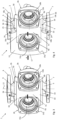
- FIGS 3, 4 and 5 show an insulating cladding consisting of three insulating elements 10, 20, 30 for a double pump 1 with a pump housing 2 comprising a first housing side 2a with a first pump chamber 16a for the impeller of a first centrifugal pump, and a second housing side 2b with a second pump chamber 16b for the impeller of a second centrifugal pump, wherein the impeller axes 9a, 9b of the first and second centrifugal pumps and thus also the drive units are arranged parallel to one another.
- FIG. 3 to 5 only the pump housing 2 without electric motor drive units, so that the view is clear of the pump flange 15a of the first centrifugal pump, which is part of the first housing part 2a, and the pump flange 15b of the second centrifugal pump, which is part of the second housing part 2b.
- the pump flanges 15a, 15b each form the mechanical interface to the drive unit of the respective centrifugal pump, so that the drive units are flanged to the pump housing 2 with the motor axis parallel and protrude from it in the axial direction.
- the pump housing 2 is also designed as an inline housing for installation in a pipeline.
- the insulating cladding according to the invention encompasses the pump housing 2 of the double pump 1 on all sides.
- it consists of a first insulating element 10, a second insulating element 20, and a third insulating element 30.
- the first insulating element 10 forms a half-shell and is designed such that it at least partially encompasses the first housing side 2a of the pump housing 2 and is attached to the pump housing 2 from a first joining direction A radially to the impeller axis 9a of the first centrifugal pump on the pump housing, as can be seen from Figure 4 becomes apparent.
- the second insulating element 20 also forms a half-shell and is designed such that it at least partially encompasses the second housing side 2b of the pump housing 2 and is attached to the pump housing 2 from a second joining direction B radially to the impeller axis 9b of the second centrifugal pump, wherein the second joining direction B is opposite to the first joining direction A, as can be seen from Figure 5 becomes clear.
- the third insulating element 30 is designed such that it is arranged on the pump housing 2 from a third joining direction C parallel to the impeller axes 9a, 9b, spatially between the mechanical interface 15a of the drive unit of the first centrifugal pump to the pump housing 2 and the mechanical interface 15b of the drive unit of the second centrifugal pump to the pump housing 2.
- the third insulating element 30 fills the area of the pump housing 2 between the first and second housing sides 2a, 2b, More precisely, between the first and second centrifugal pumps, axially approximately at the level of the pump flanges 15a, 15b, which is located behind the respective drive unit from the direction of the first joining direction A and the second joining direction B and is therefore not accessible from these directions.
- the pump housing 2 is thus covered on all sides, with the third insulating element 30 acting as an intermediate piece or central part.
- the third insulating element 30 is first attached to the pump housing 2, followed by the first insulating element 10 and then the second insulating element 20.
- the second insulating element could also be mounted first and then the first insulating element.
- the sequence is determined by a positive connection that exists between the first insulating element 10 and the third insulating element 30 as well as between the second insulating element 20 and the third insulating element 30 and which holds the insulating elements 10, 20, 30 together without the need for additional fastening means. If necessary, however, additional fastening means, such as the pins 11 in Figure 2 , are used to hold the first and second insulating elements 10, 20 together.
- the third insulating element 30 has a double-T-shaped cross-section. It consists of a central web 31 and two crossbeams 32, 33, between which the central web 31 extends. It should be noted that the central web 31 and the crossbeams 32, 33 merely form sections of the third insulating element 30, which is thus a single piece. Nevertheless, in another embodiment, the third insulating element 30 could be composed of subcomponents, such as two T-shaped or three I-shaped components.
- the crossbeams 32, 33 encompass the pump flanges 15a, 15b on the top and bottom sides approximately up to their middle in relation to their extension transverse to the impeller axes 9a, 9b, or in other words up to the height of the respective impeller axis 9a, 9b, where the first or second insulating element 10, 20 is then connected, which encompasses the remaining part of the corresponding pump flange 15a, 15b.
- the length L Q of the crossbeams 32, 33 in the direction of their The longitudinal extension thus corresponds approximately to the distance between the impeller axes 9a, 9b.
- the maximum thickness of the central web 31 in the direction transverse to its longitudinal extent and transverse to the longitudinal extent of the crossbeams 32, 33 is less than the minimum width B min of the central web 31 in the direction transverse to its longitudinal extent and in the direction of the longitudinal extent of the crossbeams 32, 33, so that the central web 31 is narrower than it is wide.
- This enables installation of the third insulating element 30 in confined spaces at the insertion end into the area between the drive units.
- the third insulating element 30 can first be rotated 90° about the longitudinal axis of its central web 31 and pushed between the drive units. It is then rotated back 90° about the longitudinal axis into the correct orientation before being attached to the pump housing 2 in the direction of the third joining direction C.
- the positive connection between the first insulating element 10 and the third insulating element 30 as well as between the second insulating element 20 and the third insulating element 30 is formed by a first tongue and groove connection between the upper crossbeam 32 and the first insulating element 10 and the third insulating element 30, and by a second tongue and groove connection between the lower crossbeam 33 and the first insulating element 10 and the third insulating element 30.
- each of the crossbeams 32, 33 has a stepped recess 34 on its front longitudinal edge.
- This recess forms a profiled, stepped longitudinal projection 35 which rises in the direction of the longitudinal extent of the central web 31 on each of the two crossbeams 32, 33 and extends parallel to the longitudinal extent of the respective crossbeam 32, 33.
- This respective longitudinal projection 35 forms the bung of the respective groove-bung connection. It is rectangular in cross-section and, when the insulation elements 10, 20, 30 are assembled, protrudes into a corresponding longitudinal groove 25, which is provided in the upper shell wall 18a and in the lower shell wall 18b of the first and second insulation elements 10, 20, respectively. See Figure 4 , where only the first insulating element 10 is shown here.
- the respective longitudinal groove 25 is directed forward, more precisely to one side transverse to its longitudinal extent is limited by a side wall 24, which in turn engages in the corresponding, previously mentioned recess 34.
- first and second insulating elements 10, 20 can each be pushed onto the third insulating element 30 from one side, since the first and second joining directions A, B are parallel to the longitudinal extent of the crossbeam. Viewed from the third joining direction C, the bung 35 on the upper and lower crossbeams 32, 33 consequently engages behind the side wall 24, which forms an undercut, thus preventing the removal of the third insulating element 30 from the form-fit connection.
- the third insulating element is thus firmly held between the first and second insulating elements without the need for additional fastening means.
- a positive connection between the first and second insulating elements 10, 20 can be provided on the non-visible rear side of the pump housing, for example, such that the rear shell wall 18c, 28c of one of the two insulating elements 10, 20 has a projecting outer edge that positively engages a recess in the outer edge of the opposite insulating element.
- additional fastening means such as pins 11 in Figure 2 , can be used to connect the first and second insulating elements 10, 20 together.
- an essential feature of the insulating cladding 10, 20, 30 according to the invention is that it consists of a small number of parts, as in this example, only three parts.
- the first, second, and/or third insulating elements 10, 20, 30 can also be constructed independently of one another in two or more parts, i.e., they can themselves consist of two or more parts, without deviating from the basic concept of the invention.
- a fourth insulating element can cover a location of the pump housing that cannot be covered by the first or second insulating element 10, 20 because, for example, from the perspective of the first or second joining direction A, B, it is behind a projecting section of the Pump housing 2, for example, on the rear side of the pump housing 2 facing away from the drive units.
- the fourth insulating element can also form a positive connection with the first and/or second insulating element 10, 20 and be held above it. Depending on requirements, it can, for example, be substantially I-shaped, T-shaped, or double-T-shaped to enable easy joining.
- the insulating elements are made of expanded polystyrene to provide good thermal insulation. They are molded bodies that are adapted to the outer shape of the pump housing.
Landscapes
- Engineering & Computer Science (AREA)
- Mechanical Engineering (AREA)
- General Engineering & Computer Science (AREA)
- Physics & Mathematics (AREA)
- Thermal Sciences (AREA)
- Structures Of Non-Positive Displacement Pumps (AREA)
Claims (15)
- Pompe double (1) avec un carter de pompe (2) comprenant un premier côté de carter (2a) avec une première chambre de pompe (16a) pour le rotor d'une première pompe centrifuge, et un second côté de carter (2b) avec une seconde chambre de pompe (16b) pour le rotor d'une seconde pompe centrifuge, sachant que les axes des rotors (9a, 9b) de la première et de la seconde pompe centrifuge sont juxtaposés parallèlement, sachant qu'un revêtement isolant (10, 20, 30) entoure le carter de pompe (2), caractérisée en ce que ce revêtement isolant (10, 20, 30) comprend- au moins un premier élément isolant (10) conçu de manière à entourer au moins partiellement le premier côté de carter (2a) du carter de pompe (2) et disposé sur le carter de pompe (2) à partir d'une première direction de jonction (A) radialement par rapport à l'axe du rotor (9a) de la première pompe centrifuge,- au moins un deuxième élément isolant (20) conçu de manière à entourer au moins partiellement le second côté de carter (2b) du carter de pompe (2) et disposé sur le carter de pompe (2) à partir d'une deuxième direction de jonction (B) radialement par rapport à l'axe du rotor (9a) de la seconde pompe centrifuge, sachant que la deuxième direction de jonction (B) est opposée à la première direction de jonction (A), et- au moins un troisième élément isolant (30) conçu de telle sorte qu'il est disposé sur le carter de pompe (2) à partir d'une troisième direction de jonction (C) parallèle aux axes des rotors (9a, 9b), dans l'espace entre une interface mécanique (15a) d'une unité d'entraînement de la première pompe centrifuge vers le carter de pompe (2) et une interface mécanique (15b) d'une unité d'entraînement de la seconde pompe centrifuge vers le carter de pompe (2).
- Pompe double (1) selon la revendication 1, caractérisée en ce que la jonction crée entre les éléments isolants (10, 20, 30) une liaison par complémentarité de forme de telle façon qu'ils sont maintenus ensemble.
- Pompe double (1) selon la revendication 1 ou 2, caractérisée en ce que le premier et/ou le deuxième élément isolant (10, 20) forment chacun une demicoque.
- Pompe double (1) selon la revendication 1, 2 ou 3, caractérisée en ce que le troisième élément isolant (30) comporte une barre centrale (31) à chaque extrémité de laquelle se trouve une barre transversale (32, 33), de sorte qu'il présente une section transversale en forme de double T.
- Pompe double (1) selon au moins la revendication 2, caractérisée en ce que la liaison par complémentarité de forme existe entre le premier et le troisième élément isolant (10, 30) d'une part et entre le deuxième et le troisième élément isolant (20, 30) d'autre part.
- Pompe double (1) selon au moins la revendication 2, caractérisée en ce que la liaison par complémentarité de forme est formée par au moins un assemblage rainure-languette (25, 35) qui s'étend le long de la première et de la deuxième direction de jonction (A, B), de sorte que le premier et le deuxième élément isolant (10, 20) peuvent être enfilés respectivement sur le troisième élément isolant (30) et qu'après l'enfilage, le troisième élément isolant (30) ne peut plus être retiré de la liaison avec le premier et le deuxième élément isolant (10, 20).
- Pompe double (1) selon au moins la revendication 4, caractérisée en ce que chacune des barres transversales (32, 33) du troisième élément isolant (30) présente une liaison par complémentarité de forme sous la forme d'un assemblage rainure-languette (25, 35) avec le premier et le deuxième élément isolant (10, 20).
- Pompe double (1) selon la revendication 6 ou 7, caractérisée en ce que la languette (35) de l'assemblage rainure-languette (25, 35) est formée par une saillie longitudinale en forme d'escalier qui s'étend dans la direction de l'extension longitudinale de la barre centrale (31) sur au moins l'une des barres transversales (32, 33) et s'étend parallèlement à l'extension longitudinale de la barre transversale (32, 33) pour faire saillie, à l'état monté, dans une rainure longitudinale correspondante (25) formée en partie dans le premier et en partie dans le deuxième élément isolant (10, 20).
- Pompe double (1) selon l'une des revendications précédentes, caractérisée en ce que le premier, le deuxième et/ou le troisième élément isolant (10, 20, 30) comprennent au moins deux parties.
- Pompe double (1) selon l'une des revendications précédentes, caractérisée par un quatrième élément isolant disposé du côté opposé au troisième élément isolant (30) sur le carter de pompe (2).
- Pompe double (1) selon au moins la revendication 4, caractérisée en ce que l'épaisseur maximale de la barre centrale (31) dans la direction transversale à son extension longitudinale et dans la direction transversale à l'extension longitudinale des barres transversales (32, 33) est égale ou inférieure à la largeur minimale de la barre centrale (31) dans la direction transversale à son extension longitudinale et dans la direction de l'extension longitudinale des barres transversales (32, 33).
- Pompe double (1) selon au moins la revendication 4, caractérisée en ce que la longueur des barres transversales (32, 33) dans le sens de leur extension longitudinale est au moins égale à la longueur de la barre centrale (31) dans le sens de son extension longitudinale.
- Pompe double (1) selon l'une des revendications précédentes, caractérisé en ce que les éléments isolants (10, 20, 30) sont composés d'une matière plastique expansée.
- Pompe double (1) selon l'une des revendications précédentes, caractérisée en ce qu'elle est une pompe en ligne.
- Procédé de montage d'un revêtement isolant (10, 20, 30) pour une pompe double (1) avec un carter de pompe (2) comprenant un premier côté de carter (2a) avec une première chambre de pompe (16a) pour le rotor d'une première pompe centrifuge, et un second côté de carter (2b) avec une seconde chambre de pompe (16b) pour le rotor d'une seconde pompe centrifuge, sachant que les axes des rotors (9a, 9b) de la première et de la seconde pompe centrifuge sont juxtaposés parallèlement, caractérisé par les étapesa) Disposition d'un troisième élément isolant (30) du revêtement isolant (10, 20, 30) sur le carter de pompe (2) entre une interface mécanique (15a) d'une unité d'entraînement de la première pompe centrifuge vers le carter de pompe (2) et une interface mécanique (15b) d'une unité d'entraînement de la deuxième pompe centrifuge vers le carter de pompe (2) par jonction axiale dans la direction d'une troisième direction de jonction (C) parallèle aux axes des rotors (9a, 9b),b) Disposition d'un premier élément isolant (10) du revêtement isolant (10, 20, 30) sur le carter de pompe (2) à partir d'une première direction de jonction (A) radialement par rapport à l'axe du rotor (9a) de la première pompe centrifuge de telle sorte qu'il soit poussé sur le troisième élément isolant (30) et qu'il entoure au moins partiellement le premier côté de carter (2a) du carter de pompe (2) dans sa position finale, etc) Disposition d'un deuxième élément isolant (20) du revêtement isolant (10, 20, 30) sur le carter de pompe (2) à partir d'une deuxième direction de jonction (B) radialement par rapport à l'axe du rotor (9a) de la seconde pompe centrifuge de telle sorte qu'il soit poussé sur le troisième élément isolant (30) et qu'il entoure au moins partiellement le premier côté de carter (2a) du carter de pompe (2) dans sa position finale, sachant que la deuxième direction de jonction (B) est opposée à la première direction de jonction (A).
Applications Claiming Priority (1)
| Application Number | Priority Date | Filing Date | Title |
|---|---|---|---|
| LU503228A LU503228B1 (de) | 2022-12-21 | 2022-12-21 | Doppelpumpe mit Isolierverkleidung und zugehöriges Montageverfahren |
Publications (2)
| Publication Number | Publication Date |
|---|---|
| EP4390140A1 EP4390140A1 (fr) | 2024-06-26 |
| EP4390140B1 true EP4390140B1 (fr) | 2025-05-28 |
Family
ID=84923125
Family Applications (1)
| Application Number | Title | Priority Date | Filing Date |
|---|---|---|---|
| EP23213033.6A Active EP4390140B1 (fr) | 2022-12-21 | 2023-11-29 | Pompe double avec revêtement isolant et procédé d'assemblage associé |
Country Status (3)
| Country | Link |
|---|---|
| EP (1) | EP4390140B1 (fr) |
| CN (1) | CN221742861U (fr) |
| LU (1) | LU503228B1 (fr) |
Family Cites Families (8)
| Publication number | Priority date | Publication date | Assignee | Title |
|---|---|---|---|---|
| DE4224853C2 (de) * | 1992-07-28 | 2001-06-21 | Wilo Gmbh | Verpackung für eine Pumpe |
| DE19511170A1 (de) | 1995-03-28 | 1996-10-02 | Wilo Gmbh | Doppelpumpe mit übergeordneter Steuerung |
| DE10257493A1 (de) * | 2002-12-10 | 2004-09-09 | Wilo Ag | Motor-Pumpen-Aggregat mit Wärmedämmungsschale |
| EP2236839B1 (fr) * | 2009-04-04 | 2013-11-13 | Grundfos Management A/S | Agrégat de pompe centrifuge |
| DE102014006258A1 (de) | 2014-04-30 | 2015-11-05 | Wilo Se | Verfahren zur Regelung eines Pumpensystems und geregeltes Pumpensystem |
| LU102816B1 (de) | 2021-06-01 | 2022-12-01 | Wilo Se | Doppelpumpenaggregat |
| FR3123704B1 (fr) * | 2021-06-04 | 2023-05-05 | A D I | Matelas isolant thermique souple |
| JP2022187176A (ja) | 2021-06-07 | 2022-12-19 | 株式会社荏原製作所 | ポンプケーシング |
-
2022
- 2022-12-21 LU LU503228A patent/LU503228B1/de active IP Right Grant
-
2023
- 2023-11-29 EP EP23213033.6A patent/EP4390140B1/fr active Active
- 2023-12-08 CN CN202323343202.XU patent/CN221742861U/zh active Active
Also Published As
| Publication number | Publication date |
|---|---|
| CN221742861U (zh) | 2024-09-20 |
| LU503228B1 (de) | 2024-06-21 |
| EP4390140A1 (fr) | 2024-06-26 |
Similar Documents
| Publication | Publication Date | Title |
|---|---|---|
| DE69528517T2 (de) | Klimaanlage | |
| EP0561037B1 (fr) | Dispositif d'alimentation pour un circuit d'une installation d'alimentation en chaleur ou en froid | |
| EP2904272B1 (fr) | Anneau de paroi pour ventilateur axial | |
| DE102011076904A1 (de) | Gekühlter Stator für Elektromotor | |
| EP2602144B1 (fr) | Extrémité frontale d'un véhicule | |
| EP4390140B1 (fr) | Pompe double avec revêtement isolant et procédé d'assemblage associé | |
| EP2107284B1 (fr) | Ebauche de boîtier de soupape, kit de soupape et groupe de soupape | |
| EP2236839B1 (fr) | Agrégat de pompe centrifuge | |
| EP0979347B1 (fr) | Dispositif d'isolation thermique pour une turbine a vapeur | |
| EP4375604B1 (fr) | Échangeur de chaleur à ailettes, son procédé de fabrication et système | |
| DE3634113C2 (fr) | ||
| DE9418919U1 (de) | Kühldecke | |
| EP0667933B1 (fr) | Groupe compresseur | |
| DE19948943C2 (de) | Eisspeicher-Baueinheit mit übereinander angeordneten Eisspeicher-Profilkörpern und dazwischen verlegtem Kältemittelrohr | |
| EP0670451B1 (fr) | Assemblage de tuyau multiple | |
| DE102006020437A1 (de) | Verbindungsvorrichtung zum Verbinden von mehreren Profilstäben | |
| EP2936602B1 (fr) | Dispositif thermiquement isolant pour la reception au moins d'un composant d'une pile à combustible à oxyde solide et son procédé de production | |
| EP1528186B1 (fr) | Panneau pour la construction de logements modulaires particulièrement pour des unités de ventilation et conditionnement d'air | |
| WO1996013667A1 (fr) | Pompe a vide a friction pourvue d'un systeme de refroidissement | |
| DE69800161T2 (de) | Radiator für Heizungsanlage mit Flüssigkeitsumlauf | |
| EP1178216B1 (fr) | Boítier de pompe | |
| EP2053327B1 (fr) | Appareil ménager | |
| DE20121414U1 (de) | Schutzgehäuse, insbesondere Instrumentenschutzhaus | |
| EP4647706A1 (fr) | Bloc de raccord pour une structure de conduite de fluide et structure de conduite de fluide d'un système de régulation de température modulaire | |
| DE9412818U1 (de) | Car Audio-Verstärker mit Zusatzkühlkörper |
Legal Events
| Date | Code | Title | Description |
|---|---|---|---|
| PUAI | Public reference made under article 153(3) epc to a published international application that has entered the european phase |
Free format text: ORIGINAL CODE: 0009012 |
|
| STAA | Information on the status of an ep patent application or granted ep patent |
Free format text: STATUS: THE APPLICATION HAS BEEN PUBLISHED |
|
| AK | Designated contracting states |
Kind code of ref document: A1 Designated state(s): AL AT BE BG CH CY CZ DE DK EE ES FI FR GB GR HR HU IE IS IT LI LT LU LV MC ME MK MT NL NO PL PT RO RS SE SI SK SM TR |
|
| STAA | Information on the status of an ep patent application or granted ep patent |
Free format text: STATUS: REQUEST FOR EXAMINATION WAS MADE |
|
| 17P | Request for examination filed |
Effective date: 20241008 |
|
| RBV | Designated contracting states (corrected) |
Designated state(s): AL AT BE BG CH CY CZ DE DK EE ES FI FR GB GR HR HU IE IS IT LI LT LU LV MC ME MK MT NL NO PL PT RO RS SE SI SK SM TR |
|
| GRAP | Despatch of communication of intention to grant a patent |
Free format text: ORIGINAL CODE: EPIDOSNIGR1 |
|
| STAA | Information on the status of an ep patent application or granted ep patent |
Free format text: STATUS: GRANT OF PATENT IS INTENDED |
|
| INTG | Intention to grant announced |
Effective date: 20250123 |
|
| GRAS | Grant fee paid |
Free format text: ORIGINAL CODE: EPIDOSNIGR3 |
|
| GRAA | (expected) grant |
Free format text: ORIGINAL CODE: 0009210 |
|
| STAA | Information on the status of an ep patent application or granted ep patent |
Free format text: STATUS: THE PATENT HAS BEEN GRANTED |
|
| AK | Designated contracting states |
Kind code of ref document: B1 Designated state(s): AL AT BE BG CH CY CZ DE DK EE ES FI FR GB GR HR HU IE IS IT LI LT LU LV MC ME MK MT NL NO PL PT RO RS SE SI SK SM TR |
|
| REG | Reference to a national code |
Ref country code: GB Ref legal event code: FG4D Free format text: NOT ENGLISH |
|
| REG | Reference to a national code |
Ref country code: CH Ref legal event code: EP |
|
| REG | Reference to a national code |
Ref country code: IE Ref legal event code: FG4D Free format text: LANGUAGE OF EP DOCUMENT: GERMAN Ref country code: DE Ref legal event code: R096 Ref document number: 502023001057 Country of ref document: DE |
|
| REG | Reference to a national code |
Ref country code: NL Ref legal event code: MP Effective date: 20250528 |
|
| PG25 | Lapsed in a contracting state [announced via postgrant information from national office to epo] |
Ref country code: FI Free format text: LAPSE BECAUSE OF FAILURE TO SUBMIT A TRANSLATION OF THE DESCRIPTION OR TO PAY THE FEE WITHIN THE PRESCRIBED TIME-LIMIT Effective date: 20250528 Ref country code: ES Free format text: LAPSE BECAUSE OF FAILURE TO SUBMIT A TRANSLATION OF THE DESCRIPTION OR TO PAY THE FEE WITHIN THE PRESCRIBED TIME-LIMIT Effective date: 20250528 |
|
| REG | Reference to a national code |
Ref country code: LT Ref legal event code: MG9D |
|
| PG25 | Lapsed in a contracting state [announced via postgrant information from national office to epo] |
Ref country code: NO Free format text: LAPSE BECAUSE OF FAILURE TO SUBMIT A TRANSLATION OF THE DESCRIPTION OR TO PAY THE FEE WITHIN THE PRESCRIBED TIME-LIMIT Effective date: 20250828 Ref country code: GR Free format text: LAPSE BECAUSE OF FAILURE TO SUBMIT A TRANSLATION OF THE DESCRIPTION OR TO PAY THE FEE WITHIN THE PRESCRIBED TIME-LIMIT Effective date: 20250829 |
|
| PG25 | Lapsed in a contracting state [announced via postgrant information from national office to epo] |
Ref country code: NL Free format text: LAPSE BECAUSE OF FAILURE TO SUBMIT A TRANSLATION OF THE DESCRIPTION OR TO PAY THE FEE WITHIN THE PRESCRIBED TIME-LIMIT Effective date: 20250528 Ref country code: PL Free format text: LAPSE BECAUSE OF FAILURE TO SUBMIT A TRANSLATION OF THE DESCRIPTION OR TO PAY THE FEE WITHIN THE PRESCRIBED TIME-LIMIT Effective date: 20250528 |
|
| PG25 | Lapsed in a contracting state [announced via postgrant information from national office to epo] |
Ref country code: BG Free format text: LAPSE BECAUSE OF FAILURE TO SUBMIT A TRANSLATION OF THE DESCRIPTION OR TO PAY THE FEE WITHIN THE PRESCRIBED TIME-LIMIT Effective date: 20250528 |
|
| PG25 | Lapsed in a contracting state [announced via postgrant information from national office to epo] |
Ref country code: HR Free format text: LAPSE BECAUSE OF FAILURE TO SUBMIT A TRANSLATION OF THE DESCRIPTION OR TO PAY THE FEE WITHIN THE PRESCRIBED TIME-LIMIT Effective date: 20250528 |
|
| PG25 | Lapsed in a contracting state [announced via postgrant information from national office to epo] |
Ref country code: RS Free format text: LAPSE BECAUSE OF FAILURE TO SUBMIT A TRANSLATION OF THE DESCRIPTION OR TO PAY THE FEE WITHIN THE PRESCRIBED TIME-LIMIT Effective date: 20250828 |
|
| PG25 | Lapsed in a contracting state [announced via postgrant information from national office to epo] |
Ref country code: IS Free format text: LAPSE BECAUSE OF FAILURE TO SUBMIT A TRANSLATION OF THE DESCRIPTION OR TO PAY THE FEE WITHIN THE PRESCRIBED TIME-LIMIT Effective date: 20250928 |
|
| PG25 | Lapsed in a contracting state [announced via postgrant information from national office to epo] |
Ref country code: LV Free format text: LAPSE BECAUSE OF FAILURE TO SUBMIT A TRANSLATION OF THE DESCRIPTION OR TO PAY THE FEE WITHIN THE PRESCRIBED TIME-LIMIT Effective date: 20250528 |
|
| PGFP | Annual fee paid to national office [announced via postgrant information from national office to epo] |
Ref country code: DE Payment date: 20251022 Year of fee payment: 3 |
|
| PG25 | Lapsed in a contracting state [announced via postgrant information from national office to epo] |
Ref country code: DK Free format text: LAPSE BECAUSE OF FAILURE TO SUBMIT A TRANSLATION OF THE DESCRIPTION OR TO PAY THE FEE WITHIN THE PRESCRIBED TIME-LIMIT Effective date: 20250528 Ref country code: SM Free format text: LAPSE BECAUSE OF FAILURE TO SUBMIT A TRANSLATION OF THE DESCRIPTION OR TO PAY THE FEE WITHIN THE PRESCRIBED TIME-LIMIT Effective date: 20250528 |
|
| PGFP | Annual fee paid to national office [announced via postgrant information from national office to epo] |
Ref country code: AT Payment date: 20260113 Year of fee payment: 3 |
|
| PGFP | Annual fee paid to national office [announced via postgrant information from national office to epo] |
Ref country code: IT Payment date: 20251201 Year of fee payment: 3 |
|
| PGFP | Annual fee paid to national office [announced via postgrant information from national office to epo] |
Ref country code: FR Payment date: 20251023 Year of fee payment: 3 |
|
| PG25 | Lapsed in a contracting state [announced via postgrant information from national office to epo] |
Ref country code: CZ Free format text: LAPSE BECAUSE OF FAILURE TO SUBMIT A TRANSLATION OF THE DESCRIPTION OR TO PAY THE FEE WITHIN THE PRESCRIBED TIME-LIMIT Effective date: 20250528 |
|
| PG25 | Lapsed in a contracting state [announced via postgrant information from national office to epo] |
Ref country code: EE Free format text: LAPSE BECAUSE OF FAILURE TO SUBMIT A TRANSLATION OF THE DESCRIPTION OR TO PAY THE FEE WITHIN THE PRESCRIBED TIME-LIMIT Effective date: 20250528 |
|
| PG25 | Lapsed in a contracting state [announced via postgrant information from national office to epo] |
Ref country code: SK Free format text: LAPSE BECAUSE OF FAILURE TO SUBMIT A TRANSLATION OF THE DESCRIPTION OR TO PAY THE FEE WITHIN THE PRESCRIBED TIME-LIMIT Effective date: 20250528 |
|
| REG | Reference to a national code |
Ref country code: DE Ref legal event code: R097 Ref document number: 502023001057 Country of ref document: DE |
|
| PG25 | Lapsed in a contracting state [announced via postgrant information from national office to epo] |
Ref country code: RO Free format text: LAPSE BECAUSE OF FAILURE TO SUBMIT A TRANSLATION OF THE DESCRIPTION OR TO PAY THE FEE WITHIN THE PRESCRIBED TIME-LIMIT Effective date: 20250528 |
|
| PLBE | No opposition filed within time limit |
Free format text: ORIGINAL CODE: 0009261 |
|
| STAA | Information on the status of an ep patent application or granted ep patent |
Free format text: STATUS: NO OPPOSITION FILED WITHIN TIME LIMIT |
|
| REG | Reference to a national code |
Ref country code: CH Ref legal event code: L10 Free format text: ST27 STATUS EVENT CODE: U-0-0-L10-L00 (AS PROVIDED BY THE NATIONAL OFFICE) Effective date: 20260409 |