EP4390143A1 - Dispositif de guidage de flux et unité de ventilateur dotée du dispositif de guidage de flux - Google Patents
Dispositif de guidage de flux et unité de ventilateur dotée du dispositif de guidage de flux Download PDFInfo
- Publication number
- EP4390143A1 EP4390143A1 EP23213204.3A EP23213204A EP4390143A1 EP 4390143 A1 EP4390143 A1 EP 4390143A1 EP 23213204 A EP23213204 A EP 23213204A EP 4390143 A1 EP4390143 A1 EP 4390143A1
- Authority
- EP
- European Patent Office
- Prior art keywords
- flow
- flow guiding
- fan
- guiding device
- web structure
- Prior art date
- Legal status (The legal status is an assumption and is not a legal conclusion. Google has not performed a legal analysis and makes no representation as to the accuracy of the status listed.)
- Pending
Links
- 230000007423 decrease Effects 0.000 claims description 8
- 238000009434 installation Methods 0.000 description 6
- 230000007704 transition Effects 0.000 description 4
- 238000011161 development Methods 0.000 description 3
- 230000018109 developmental process Effects 0.000 description 3
- 238000001816 cooling Methods 0.000 description 2
- 238000009499 grossing Methods 0.000 description 1
- 238000004519 manufacturing process Methods 0.000 description 1
Images



Classifications
-
- F—MECHANICAL ENGINEERING; LIGHTING; HEATING; WEAPONS; BLASTING
- F04—POSITIVE - DISPLACEMENT MACHINES FOR LIQUIDS; PUMPS FOR LIQUIDS OR ELASTIC FLUIDS
- F04D—NON-POSITIVE-DISPLACEMENT PUMPS
- F04D29/00—Details, component parts, or accessories
- F04D29/70—Suction grids; Strainers; Dust separation; Cleaning
- F04D29/701—Suction grids; Strainers; Dust separation; Cleaning especially adapted for elastic fluid pumps
- F04D29/703—Suction grids; Strainers; Dust separation; Cleaning especially adapted for elastic fluid pumps specially for fans, e.g. fan guards
-
- F—MECHANICAL ENGINEERING; LIGHTING; HEATING; WEAPONS; BLASTING
- F04—POSITIVE - DISPLACEMENT MACHINES FOR LIQUIDS; PUMPS FOR LIQUIDS OR ELASTIC FLUIDS
- F04D—NON-POSITIVE-DISPLACEMENT PUMPS
- F04D25/00—Pumping installations or systems
- F04D25/02—Units comprising pumps and their driving means
- F04D25/08—Units comprising pumps and their driving means the working fluid being air, e.g. for ventilation
-
- F—MECHANICAL ENGINEERING; LIGHTING; HEATING; WEAPONS; BLASTING
- F04—POSITIVE - DISPLACEMENT MACHINES FOR LIQUIDS; PUMPS FOR LIQUIDS OR ELASTIC FLUIDS
- F04D—NON-POSITIVE-DISPLACEMENT PUMPS
- F04D29/00—Details, component parts, or accessories
- F04D29/40—Casings; Connections of working fluid
- F04D29/42—Casings; Connections of working fluid for radial or helico-centrifugal pumps
- F04D29/44—Fluid-guiding means, e.g. diffusers
- F04D29/441—Fluid-guiding means, e.g. diffusers especially adapted for elastic fluid pumps
- F04D29/444—Bladed diffusers
-
- F—MECHANICAL ENGINEERING; LIGHTING; HEATING; WEAPONS; BLASTING
- F04—POSITIVE - DISPLACEMENT MACHINES FOR LIQUIDS; PUMPS FOR LIQUIDS OR ELASTIC FLUIDS
- F04D—NON-POSITIVE-DISPLACEMENT PUMPS
- F04D29/00—Details, component parts, or accessories
- F04D29/40—Casings; Connections of working fluid
- F04D29/52—Casings; Connections of working fluid for axial pumps
- F04D29/54—Fluid-guiding means, e.g. diffusers
- F04D29/541—Specially adapted for elastic fluid pumps
- F04D29/542—Bladed diffusers
- F04D29/544—Blade shapes
-
- F—MECHANICAL ENGINEERING; LIGHTING; HEATING; WEAPONS; BLASTING
- F04—POSITIVE - DISPLACEMENT MACHINES FOR LIQUIDS; PUMPS FOR LIQUIDS OR ELASTIC FLUIDS
- F04D—NON-POSITIVE-DISPLACEMENT PUMPS
- F04D29/00—Details, component parts, or accessories
- F04D29/60—Mounting; Assembling; Disassembling
- F04D29/64—Mounting; Assembling; Disassembling of axial pumps
- F04D29/644—Mounting; Assembling; Disassembling of axial pumps especially adapted for elastic fluid pumps
- F04D29/646—Mounting or removal of fans
-
- F—MECHANICAL ENGINEERING; LIGHTING; HEATING; WEAPONS; BLASTING
- F04—POSITIVE - DISPLACEMENT MACHINES FOR LIQUIDS; PUMPS FOR LIQUIDS OR ELASTIC FLUIDS
- F04D—NON-POSITIVE-DISPLACEMENT PUMPS
- F04D29/00—Details, component parts, or accessories
- F04D29/66—Combating cavitation, whirls, noise, vibration or the like; Balancing
- F04D29/661—Combating cavitation, whirls, noise, vibration or the like; Balancing especially adapted for elastic fluid pumps
- F04D29/666—Combating cavitation, whirls, noise, vibration or the like; Balancing especially adapted for elastic fluid pumps by means of rotor construction or layout, e.g. unequal distribution of blades or vanes
-
- F—MECHANICAL ENGINEERING; LIGHTING; HEATING; WEAPONS; BLASTING
- F04—POSITIVE - DISPLACEMENT MACHINES FOR LIQUIDS; PUMPS FOR LIQUIDS OR ELASTIC FLUIDS
- F04D—NON-POSITIVE-DISPLACEMENT PUMPS
- F04D25/00—Pumping installations or systems
- F04D25/02—Units comprising pumps and their driving means
- F04D25/06—Units comprising pumps and their driving means the pump being electrically driven
- F04D25/0606—Units comprising pumps and their driving means the pump being electrically driven the electric motor being specially adapted for integration in the pump
- F04D25/0613—Units comprising pumps and their driving means the pump being electrically driven the electric motor being specially adapted for integration in the pump the electric motor being of the inside-out type, i.e. the rotor is arranged radially outside a central stator
-
- F—MECHANICAL ENGINEERING; LIGHTING; HEATING; WEAPONS; BLASTING
- F05—INDEXING SCHEMES RELATING TO ENGINES OR PUMPS IN VARIOUS SUBCLASSES OF CLASSES F01-F04
- F05D—INDEXING SCHEME FOR ASPECTS RELATING TO NON-POSITIVE-DISPLACEMENT MACHINES OR ENGINES, GAS-TURBINES OR JET-PROPULSION PLANTS
- F05D2250/00—Geometry
- F05D2250/50—Inlet or outlet
- F05D2250/51—Inlet
Definitions
- the invention relates to a flow guiding device for arrangement on a suction side of a fan device and a fan unit with a fan device and the flow guiding device for arrangement on a suction side of the fan device.
- a flow guiding device for arrangement on a suction side of a fan device.
- the flow guiding device has a radial outer region and a central region.
- the radial outer region is arranged radially outside the central region with respect to a central axis of the flow guiding device.
- a flow-rectifying grid web structure with flow guiding elements is provided, which delimits a plurality of grid openings for sucking in air.
- a fan receptacle for fixing the fan device is formed in the central region.
- a frame element with at least one fastening means, in particular with recesses for receiving a further fastening means, such as a screw, is arranged, via which the flow guiding device can be fastened together with the fan device fixed to it.
- the flow guide device provides a suction-side flow-rectifying element which simultaneously takes over the support function of the fan and thus makes an additional support structure, such as suction-side or pressure-side support struts, obsolete.
- a fan can be fixed and positioned exclusively by means of the flow guide device.
- a corresponding design of the flow guide device with flow-smoothing flow guide elements dampens or breaks up large-scale turbulent flow structures. This results in a reduction in fan noise compared to an installation with an additional, separate support structure.
- the grid web structure comprises circumferential webs spaced apart in the radial direction, preferably concentrically, and radial webs spaced apart in a circumferential direction, which are arranged in particular in a sickle shape or offset from one another and which in particular do not extend continuously over all circumferential webs, but only over two or more of the circumferential webs, or have a honeycomb structure.
- the circumferential webs can be circular, oval, wave-shaped, polygonal, elliptical or rectangular.
- a flow-rectifying grid web structure with unevenly distributed flow guide elements or wave-shaped webs, in particular radial and/or circumferential webs, would also be conceivable.
- the number of radial webs extending in the circumferential direction decreases from the outside to the inside.
- the number of radial webs extending over a circumferential web is a prime number in each case.
- an embodiment is advantageous in which, viewed in the direction of flow, the flow guide elements, in particular a surface of the flow guide elements that guides the flow, are aligned in the radial outer region towards the central axis and in the central region away from the central axis.
- the flow guide elements are designed in such a way that an intake flow in the radial outer region is directed in the direction the central axis or is directed away from the central axis in the central region.
- a corresponding arrangement of the flow guide elements can be varied so that the flow guide elements are directed away from the central axis in the radial outer region and towards the central axis in the central region.
- the corresponding arrangement or orientation of the flow guide elements is predetermined during manufacture of the flow guide device in accordance with an intended application.
- a flow cross section of the grid web structure between two adjacent flow guide elements decreases from the outside to the inside.
- the invention provides that an inlet nozzle is arranged on the inside of the radial outer region, in particular in a radial outer edge region of the grid web structure.
- the flow guiding device is designed such that a flow cross section formed by the grid web structure between the flow guiding elements and the inlet nozzle decreases from the outside to the inside.
- the flow guiding device is designed in one embodiment such that in the region of the inlet nozzle an angle ⁇ 1 between a respective flow guiding element, in particular a surface of the respective flow guiding element that guides the flow, and the central axis is between 0° and 90°, preferably between 40° and 70°.
- the flow guide device is designed as a single piece or the grid web structure with the frame element and the inlet nozzle are each designed as a single piece.
- the two-part A preferred embodiment is one in which one part is formed from the grid web structure and the frame element as a single piece and the other part is formed from the inlet nozzle.
- the grid web structure, the frame element and the inlet nozzle are each formed as a single, separate component.
- the fan holder is arranged, in particular in the flow direction and/or on the inside, axially protruding from a radial plane of the frame element or in the radial plane of the frame element.
- the fan holder is designed in a step-like manner in the direction of the central axis or as a flat plate which is arranged perpendicular to the central axis.
- a cable channel is formed which extends from the fan holder to the frame element.
- a connection opening for a line of the fan device is provided in particular in the frame element.
- a jacket spanned by the lattice web structure has a convex curvature or is wave-shaped or extends in a straight line along a plane.
- the flow guide device is designed in such a way that the frame element has on the outside a convex projection for flow guidance, which runs around the lattice web structure, in particular in a transition area to the lattice web structure.
- the projection merges into the contour of the inlet nozzle.
- a Curvature of the projection varies in the course around the grid web structure.
- the flow guide device is aerodynamically adapted to the inlet nozzle, particularly on the suction side in the transition from the frame element to the inlet nozzle, by means of a convex, circumferential projection which merges into the contour of the inlet nozzle.
- the frame element thus takes over part of the function of the inlet nozzle and thereby enables a compact axial installation space.
- a design is also conceivable in which the curvature of the projection is constant in the course around the grid web structure.
- the frame element does not have a convex projection, but has a flat surface on the outside, which merges directly and straight into the inlet nozzle.
- the invention provides that the frame element is a substantially cuboid-shaped, rectangular, circular, cylindrical or elliptical plate.
- a fan unit with a fan device in particular an axial fan, a diagonal fan or a radial fan, and a flow guide device for arrangement on a suction side of the fan device according to the above disclosure is further proposed.
- the fan device comprises an electric motor which is fixed to the fan mount.
- the fan device is fixed to the fan mount exclusively by means of the electric motor.
- the flow guiding device provides a suction-side flow-rectifying element which simultaneously takes over the supporting function of the fan device and thus makes an additional support structure, such as suction-side or pressure-side support struts, obsolete.
- the fan device including the motor and electronics is positioned and fixed solely by the flow guide device.
- the fan holder is a contact guard for the fan device.
- a further advantageous embodiment is one in which the fan holder comprises a convexly curved motor cover for the electric motor of the fan device on the outside. In particular, recesses are provided for a cooling air flow. This results in a uniform flow around a hub area of the fan unit.
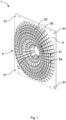
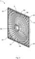
- FIGS. 1 to 3 show various representations of a flow guiding device 1 for arrangement on a suction side of a fan device 10, with a radial outer region 2 and a central region 3.
- Figure 1 shows a perspective view of the flow guide device 1 seen from the suction side and Figure 2 another perspective view of the Flow guide device 1 from a pressure side opposite the suction side
- the radial outer region 2 is arranged radially outside the central region 3 with respect to a central axis 4 of the flow guide device 1.
- a flow-rectifying grid web structure 5 with flow guide elements 54 is provided, which delimits a plurality of grid openings 51 for intake of air.
- a fan receptacle 52 for fixing the fan device 10 is formed in the central region 3. Furthermore, in the radial outer region 2 around the grid web structure 5, a frame element 6 with four fastening means 61 is arranged, via which the flow guide device 1 can be fastened together with the fan device 10 fixed thereto.
- the respective fastening means 61 is a recess, in particular a through hole, through which, for example, a screw for fixing the flow guide device can be passed.
- the frame element 6 is a cuboid-shaped plate in the embodiment shown, but can alternatively also have another geometric shape, such as a cylindrical, rectangular, circular or elliptical plate.
- the lattice web structure 5 comprises radial webs 55 spaced apart in a circumferential direction and concentrically arranged circumferential webs 56 spaced apart in the radial direction, and a shell spanned by the lattice web structure 5 has a convex curvature.
- Figure 2 it is shown that the frame element 6 is recessed on the inside of the flow guide device 1 to reduce weight.
- the grid web structure 5 is continued accordingly in the recessed area, whereby a plurality of chambers are formed on the inside of the frame element 6.
- the fan holder 52 is arranged axially on the inside, protruding from a radial plane of the frame element 6.
- the fan holder 52 is designed in a step-like manner in the direction of the central axis 4.
- Four through holes or blind holes are provided on one of the steps of the fan holder 52 for fixing the fan device.
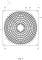
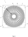
- Figure 4 shows a plan view of an alternative flow guide device 1. Since the features of this flow guide device 1 essentially correspond to the features of the Figures 1 to 3 described flow guide device 1, only different features are discussed below.
- the lattice structure 5 of the Figure 4 The flow guide device 1 shown comprises radial webs 55 spaced apart and sickled in a circumferential direction and concentrically arranged circumferential webs 56 spaced apart in the radial direction.
- the sickled radial webs 55 extend in a straight line in the central region 3 and in an arc in the outer region 2.
- some of the radial webs 55 do not extend continuously over all of the circumferential webs 56, but only over two or more of the circumferential webs 56.
- FIG 5 is a plan view of another alternative flow guide device 1. Since the features of this flow guide device 1 essentially correspond to the features of the Figures 1 to 3 described Flow guiding device 1, only different features are discussed below.
- the lattice structure 5 of the Figure 5 The flow guide device 1 shown comprises radial webs 55 which are spaced apart and offset from one another in a circumferential direction and concentrically arranged circumferential webs 56 which are spaced apart in the radial direction.
- a corresponding radial web 55 of the offset radial webs 55 extends from one of the circumferential webs 56 to an adjacent circumferential web 56.
- a further radial web 55 extending from the adjacent circumferential web 56 to a further adjacent circumferential web 56 extends offset in the radial direction from the one corresponding radial web 55.
- the number of radial webs 55 which extend in the circumferential direction decreases from the outside to the inside.
- the number of radial webs 55 which extend over a circumferential web 56 is in each case a prime number.
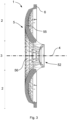
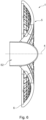
- FIG. 6 shows a sectional view of yet another alternative flow guide device 1. Since the features of this flow guide device 1 essentially correspond to the features of the Figures 1 to 3 described flow guide device 1, only different features are discussed below.
- the fan holder 52 is arranged axially on the inside, protruding from a radial plane of the frame element 6.
- the fan holder 52 is arranged axially on the outside, protruding from a radial plane of the frame element 6.
- the fan holder 52 extends in a dome-shaped manner towards the outside and also projects beyond the circumferential webs in the axial direction. 56 and radial webs 55.
- the fan holder 52 extends in a dome-shaped manner towards the outside in such a way that the axial distance between the circumferential webs 56 and radial webs 55 relative to the fan holder 52 protruding axially on the outside is at least 10% of the radial extension of the outer region 2.
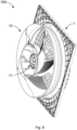
- FIGS 7 to 11 are various views of a fan unit 100 with the Figures 1 to 3 shown flow guide device 1.
- the fan unit 100 comprises a fan device 10 and the flow guide device 1, which is arranged on a suction side of the fan device 10.
- the fan device 10 comprises an electric motor 11, which is fixed to the fan holder 52.
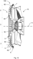
- Figures 10 and 11 it can be seen that the fan device 10 is fixed to the fan holder 52 exclusively by means of the electric motor 11.
- the fan holder 52 forms a contact protection for the fan device 10.
- the fan holder 52 comprises a motor cover that is convexly curved on the outside for the electric motor 11 of the fan device 10. Recesses for a cooling air flow are provided in the motor cover.
- a flow cross section of the grid web structure 5 between two adjacent flow guide elements 54 decreases from the outside to the inside. Furthermore, viewed in the flow direction, the flow guide elements 54 are aligned in the radial outer region 2 toward the central axis 4 and in the central region away from the central axis 4.
- an inlet nozzle 7 is arranged on the inside of the radial outer region 2, in a radial outer edge region of the grid web structure 5.
- a flow cross section formed by the grid web structure 5 between the flow guide elements 54 and the inlet nozzle 7 decreases from the outside to the inside.
- an angle ⁇ 1 between a respective flow guide element 54 and the central axis 4 is between 0° and 90°. In the embodiment shown, ⁇ 1 is equal to 50°.
- the grid structure 5 with the frame element 6 and the inlet nozzle 7 are each formed in one piece.
- a cable duct (not shown) is formed which extends from the fan holder 52 to the frame element 6.
- the frame element 6 has on the outside a convex projection 62 for flow guidance, which runs around the lattice web structure 5 in a transition area to the lattice web structure 5.
- the flow guide device 1 is aerodynamically adapted to the inlet nozzle 7 on the suction side in the transition from the frame element 6 to the inlet nozzle 7 by the convex, circumferential projection 62, which merges into the contour of the inlet nozzle 7.
- the frame element 6 thus takes over part of the function of the inlet nozzle 7 and thus enables a compact axial installation space.
- a curvature of the projection 62 varies. In the area of the corners of the cuboid frame element 6, the local flow deflection from a radial to an axial direction is small.
- a corresponding sectional view of the fan unit 100 with the flow guide device 1 is shown in Figure 11
- Figure 10 that the contour of the projection 62 has a stronger curvature in the area of Constrictions 63 in order to enable the most compact installation space or the smallest possible edge dimension of the frame element 6.
- the connection of the inlet nozzle 7 to the frame element 6 has a non-circular contour in plan view ( Fig.9 ).
- the projection 62 extends parallel to an outer edge of the cuboid-shaped frame element 6 and in the region of the corners of the frame element 6, the projection 62 extends in the shape of a circular arc.
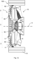
- FIG 12 is a sectional view of an alternative fan unit 100 with the flow guide device 1. Since the features of this fan unit 100 essentially correspond to the features of the Figures 7 to 11 described fan unit 100, only different features are discussed below.
- the fan unit 100 is a compact fan and further comprises a housing 111 arranged on the flow guide device 1.
- the housing extends completely around the flow guide device 1 and also accommodates the fan 10.
- the housing 111 extends from a maximum of the axial extension of the flow guide device 1 on the outside to a maximum of the axial extension of the fan 10 on the inside or by a certain amount beyond the maximum of the axial extension of the fan 10 on the inside.
- the housing extends from the frame element 6 in the direction of the inside to a maximum of the axial extension of the fan 10 on the inside or by a certain amount beyond the maximum of the axial extension of the fan 10 on the inside.
Landscapes
- Engineering & Computer Science (AREA)
- Mechanical Engineering (AREA)
- General Engineering & Computer Science (AREA)
- Physics & Mathematics (AREA)
- Geometry (AREA)
- Structures Of Non-Positive Displacement Pumps (AREA)
Applications Claiming Priority (1)
| Application Number | Priority Date | Filing Date | Title |
|---|---|---|---|
| DE102022134377.4A DE102022134377A1 (de) | 2022-12-21 | 2022-12-21 | Strömungsleitvorrichtung und Ventilatoreinheit mit der Strömungsleitvorrichtung |
Publications (1)
| Publication Number | Publication Date |
|---|---|
| EP4390143A1 true EP4390143A1 (fr) | 2024-06-26 |
Family
ID=89030116
Family Applications (1)
| Application Number | Title | Priority Date | Filing Date |
|---|---|---|---|
| EP23213204.3A Pending EP4390143A1 (fr) | 2022-12-21 | 2023-11-30 | Dispositif de guidage de flux et unité de ventilateur dotée du dispositif de guidage de flux |
Country Status (2)
| Country | Link |
|---|---|
| EP (1) | EP4390143A1 (fr) |
| DE (1) | DE102022134377A1 (fr) |
Families Citing this family (1)
| Publication number | Priority date | Publication date | Assignee | Title |
|---|---|---|---|---|
| DE102024207656A1 (de) * | 2024-08-12 | 2026-02-12 | Ziehl-Abegg Se | Einströmdüse für einen Radial-, Diagonal- oder Axialventilator und Radial-, Diagonal- oder Axialventilator mit Einströmdüse |
Citations (4)
| Publication number | Priority date | Publication date | Assignee | Title |
|---|---|---|---|---|
| GB2168756A (en) * | 1984-12-03 | 1986-06-25 | Papst Motoren Gmbh & Co Kg | Axial flow fans |
| EP0547253B1 (fr) * | 1991-12-14 | 1995-06-14 | Süd-Electric GmbH | Appareil d'homogénéisation d'un courant pour un ventilateur |
| US20150330411A1 (en) * | 2012-10-08 | 2015-11-19 | Ebm-Papst Mulfingen Gmbh & Co. Kg | Flow Rectifier for an Axial Fan |
| CN109990328A (zh) * | 2017-12-29 | 2019-07-09 | 青岛海尔智能技术研发有限公司 | 一种吸油烟机及其风机组件 |
Family Cites Families (7)
| Publication number | Priority date | Publication date | Assignee | Title |
|---|---|---|---|---|
| WO2006042635A1 (fr) * | 2004-10-19 | 2006-04-27 | Ebm-Papst St. Georgen Gmbh & Co. Kg | Dispositif pour refroidir une carte de circuits ou similaire |
| ATE422619T1 (de) * | 2006-08-30 | 2009-02-15 | Ralf Meier | Strömungsgleichrichter für einen ventilator |
| HUE026127T2 (hu) * | 2012-10-08 | 2016-05-30 | Ebm Papst Mulfingen Gmbh & Co Kg | Ház axiális ventilátorhoz |
| DE102013223983A1 (de) * | 2013-11-25 | 2015-05-28 | Ebm-Papst Mulfingen Gmbh & Co. Kg | Lüfterbaueinheit |
| DE202014105284U1 (de) * | 2014-11-04 | 2014-12-08 | Ebm-Papst Mulfingen Gmbh & Co. Kg | Schutzgitter mit verbessertem Wirkungsgrad- und Geräuschverhalten |
| DE102017209291A1 (de) * | 2017-06-01 | 2018-12-06 | Ziehl-Abegg Se | Ventilator und Vorleitgitter für einen Ventilator |
| DE102018128824A1 (de) * | 2018-11-16 | 2020-05-20 | Ebm-Papst Mulfingen Gmbh & Co. Kg | Diagonalventilator mit Gehäuse |
-
2022
- 2022-12-21 DE DE102022134377.4A patent/DE102022134377A1/de active Pending
-
2023
- 2023-11-30 EP EP23213204.3A patent/EP4390143A1/fr active Pending
Patent Citations (4)
| Publication number | Priority date | Publication date | Assignee | Title |
|---|---|---|---|---|
| GB2168756A (en) * | 1984-12-03 | 1986-06-25 | Papst Motoren Gmbh & Co Kg | Axial flow fans |
| EP0547253B1 (fr) * | 1991-12-14 | 1995-06-14 | Süd-Electric GmbH | Appareil d'homogénéisation d'un courant pour un ventilateur |
| US20150330411A1 (en) * | 2012-10-08 | 2015-11-19 | Ebm-Papst Mulfingen Gmbh & Co. Kg | Flow Rectifier for an Axial Fan |
| CN109990328A (zh) * | 2017-12-29 | 2019-07-09 | 青岛海尔智能技术研发有限公司 | 一种吸油烟机及其风机组件 |
Also Published As
| Publication number | Publication date |
|---|---|
| DE102022134377A1 (de) | 2024-06-27 |
Similar Documents
| Publication | Publication Date | Title |
|---|---|---|
| EP2815130B1 (fr) | Diffuseur, ventilateur comportant un tel diffuseur et appareil comprenant de tels ventilateurs | |
| DE602004012549T2 (de) | Kühllüfteranordnung für kraftwagenbrennkraftmaschine | |
| EP3405679B1 (fr) | Ventilateur diagonal | |
| DE202014011454U1 (de) | Gebläseeinrichtung und Außeneinheit einer Klimaanlage, welche diese umfasst | |
| CH662623A5 (de) | Einbaurahmen fuer einen ventilator. | |
| EP3325812B1 (fr) | Machine à canal latéral (compresseur, pompe à vide, ou ventilateur) avec un conduit de purge dans le barrage | |
| EP1144870A2 (fr) | Ensemble soufflante | |
| EP3784910A1 (fr) | Enveloppe de ventilateur et ventilateur | |
| EP3865711B1 (fr) | Ventilateur pourvu de plaque de recouvrement sur la cloche de rotor | |
| EP4390143A1 (fr) | Dispositif de guidage de flux et unité de ventilateur dotée du dispositif de guidage de flux | |
| DE102020200363A1 (de) | Tragmodul für einen Ventilator und Ventilator mit einem entsprechenden Tragmodul | |
| DE202016106538U1 (de) | Diagonalventilator | |
| EP3592987B1 (fr) | Carter semi-hélicoïdal | |
| DE10319270A1 (de) | Zentrifugalgebläse mit in einem Spiralgehäuse angeordnetem Zentrifugallüfter | |
| EP2716916B1 (fr) | Unité de ventilateur | |
| EP3833873A1 (fr) | Dispositif de guidage d'air pour une installation de ventilation | |
| DE69606949T2 (de) | Mit verbesserter, interner Lüftungsvorrichtung versehene Lichtmaschine | |
| EP3683451B1 (fr) | Dispositif de guidage de flux et agencement de ventilateur pourvu de dispositif de guidage de flux | |
| DE102020119881A1 (de) | Rohrventilator ausgeführt als Radialventilator | |
| WO2020099035A1 (fr) | Ventilateur diagonal pouvant être combiné de manière variable à différentes buses | |
| DE102005026420B4 (de) | Wärme ableitende Vorrichtung | |
| WO2025176247A1 (fr) | Module de support pour un ventilateur et ventilateur ayant un module de support | |
| DE9110195U1 (de) | Ventilator | |
| DE102023004570A1 (de) | Kühleinrichtung für einen Elektromotor, insbesondere einen EC-Motor, sowie Elektromotor, insbesondere EC-Motor | |
| EP4430310A1 (fr) | Ventilateur et structure de refroidissement pour ventilateur |
Legal Events
| Date | Code | Title | Description |
|---|---|---|---|
| PUAI | Public reference made under article 153(3) epc to a published international application that has entered the european phase |
Free format text: ORIGINAL CODE: 0009012 |
|
| STAA | Information on the status of an ep patent application or granted ep patent |
Free format text: STATUS: THE APPLICATION HAS BEEN PUBLISHED |
|
| AK | Designated contracting states |
Kind code of ref document: A1 Designated state(s): AL AT BE BG CH CY CZ DE DK EE ES FI FR GB GR HR HU IE IS IT LI LT LU LV MC ME MK MT NL NO PL PT RO RS SE SI SK SM TR |
|
| STAA | Information on the status of an ep patent application or granted ep patent |
Free format text: STATUS: REQUEST FOR EXAMINATION WAS MADE |
|
| 17P | Request for examination filed |
Effective date: 20241031 |
|
| RBV | Designated contracting states (corrected) |
Designated state(s): AL AT BE BG CH CY CZ DE DK EE ES FI FR GB GR HR HU IE IS IT LI LT LU LV MC ME MK MT NL NO PL PT RO RS SE SI SK SM TR |