EP4390208A2 - Machine de travail - Google Patents
Machine de travail Download PDFInfo
- Publication number
- EP4390208A2 EP4390208A2 EP24174643.7A EP24174643A EP4390208A2 EP 4390208 A2 EP4390208 A2 EP 4390208A2 EP 24174643 A EP24174643 A EP 24174643A EP 4390208 A2 EP4390208 A2 EP 4390208A2
- Authority
- EP
- European Patent Office
- Prior art keywords
- hydrogen
- cabin
- tractor
- tanks
- wall
- Prior art date
- Legal status (The legal status is an assumption and is not a legal conclusion. Google has not performed a legal analysis and makes no representation as to the accuracy of the status listed.)
- Withdrawn
Links
Images


Classifications
-
- B—PERFORMING OPERATIONS; TRANSPORTING
- B60—VEHICLES IN GENERAL
- B60L—PROPULSION OF ELECTRICALLY-PROPELLED VEHICLES; SUPPLYING ELECTRIC POWER FOR AUXILIARY EQUIPMENT OF ELECTRICALLY-PROPELLED VEHICLES; ELECTRODYNAMIC BRAKE SYSTEMS FOR VEHICLES IN GENERAL; MAGNETIC SUSPENSION OR LEVITATION FOR VEHICLES; MONITORING OPERATING VARIABLES OF ELECTRICALLY-PROPELLED VEHICLES; ELECTRIC SAFETY DEVICES FOR ELECTRICALLY-PROPELLED VEHICLES
- B60L50/00—Electric propulsion with power supplied within the vehicle
- B60L50/50—Electric propulsion with power supplied within the vehicle using propulsion power supplied by batteries or fuel cells
- B60L50/70—Electric propulsion with power supplied within the vehicle using propulsion power supplied by batteries or fuel cells using power supplied by fuel cells
- B60L50/71—Arrangement of fuel cells within vehicles specially adapted for electric vehicles
-
- B—PERFORMING OPERATIONS; TRANSPORTING
- B60—VEHICLES IN GENERAL
- B60K—ARRANGEMENT OR MOUNTING OF PROPULSION UNITS OR OF TRANSMISSIONS IN VEHICLES; ARRANGEMENT OR MOUNTING OF PLURAL DIVERSE PRIME-MOVERS IN VEHICLES; AUXILIARY DRIVES FOR VEHICLES; INSTRUMENTATION OR DASHBOARDS FOR VEHICLES; ARRANGEMENTS IN CONNECTION WITH COOLING, AIR INTAKE, GAS EXHAUST OR FUEL SUPPLY OF PROPULSION UNITS IN VEHICLES
- B60K15/00—Arrangement in connection with fuel supply of combustion engines or other fuel consuming energy converters, e.g. fuel cells; Mounting or construction of fuel tanks
- B60K15/03—Fuel tanks
- B60K15/063—Arrangement of tanks
-
- B—PERFORMING OPERATIONS; TRANSPORTING
- B60—VEHICLES IN GENERAL
- B60K—ARRANGEMENT OR MOUNTING OF PROPULSION UNITS OR OF TRANSMISSIONS IN VEHICLES; ARRANGEMENT OR MOUNTING OF PLURAL DIVERSE PRIME-MOVERS IN VEHICLES; AUXILIARY DRIVES FOR VEHICLES; INSTRUMENTATION OR DASHBOARDS FOR VEHICLES; ARRANGEMENTS IN CONNECTION WITH COOLING, AIR INTAKE, GAS EXHAUST OR FUEL SUPPLY OF PROPULSION UNITS IN VEHICLES
- B60K15/00—Arrangement in connection with fuel supply of combustion engines or other fuel consuming energy converters, e.g. fuel cells; Mounting or construction of fuel tanks
- B60K15/03—Fuel tanks
- B60K15/03006—Gas tanks
-
- B—PERFORMING OPERATIONS; TRANSPORTING
- B60—VEHICLES IN GENERAL
- B60K—ARRANGEMENT OR MOUNTING OF PROPULSION UNITS OR OF TRANSMISSIONS IN VEHICLES; ARRANGEMENT OR MOUNTING OF PLURAL DIVERSE PRIME-MOVERS IN VEHICLES; AUXILIARY DRIVES FOR VEHICLES; INSTRUMENTATION OR DASHBOARDS FOR VEHICLES; ARRANGEMENTS IN CONNECTION WITH COOLING, AIR INTAKE, GAS EXHAUST OR FUEL SUPPLY OF PROPULSION UNITS IN VEHICLES
- B60K15/00—Arrangement in connection with fuel supply of combustion engines or other fuel consuming energy converters, e.g. fuel cells; Mounting or construction of fuel tanks
- B60K15/03—Fuel tanks
- B60K15/063—Arrangement of tanks
- B60K15/067—Mounting of tanks
- B60K15/07—Mounting of tanks of gas tanks
-
- B—PERFORMING OPERATIONS; TRANSPORTING
- B60—VEHICLES IN GENERAL
- B60L—PROPULSION OF ELECTRICALLY-PROPELLED VEHICLES; SUPPLYING ELECTRIC POWER FOR AUXILIARY EQUIPMENT OF ELECTRICALLY-PROPELLED VEHICLES; ELECTRODYNAMIC BRAKE SYSTEMS FOR VEHICLES IN GENERAL; MAGNETIC SUSPENSION OR LEVITATION FOR VEHICLES; MONITORING OPERATING VARIABLES OF ELECTRICALLY-PROPELLED VEHICLES; ELECTRIC SAFETY DEVICES FOR ELECTRICALLY-PROPELLED VEHICLES
- B60L50/00—Electric propulsion with power supplied within the vehicle
- B60L50/50—Electric propulsion with power supplied within the vehicle using propulsion power supplied by batteries or fuel cells
- B60L50/70—Electric propulsion with power supplied within the vehicle using propulsion power supplied by batteries or fuel cells using power supplied by fuel cells
- B60L50/72—Constructional details of fuel cells specially adapted for electric vehicles
-
- F—MECHANICAL ENGINEERING; LIGHTING; HEATING; WEAPONS; BLASTING
- F17—STORING OR DISTRIBUTING GASES OR LIQUIDS
- F17C—VESSELS FOR CONTAINING OR STORING COMPRESSED, LIQUEFIED OR SOLIDIFIED GASES; FIXED-CAPACITY GAS-HOLDERS; FILLING VESSELS WITH, OR DISCHARGING FROM VESSELS, COMPRESSED, LIQUEFIED, OR SOLIDIFIED GASES
- F17C1/00—Pressure vessels, e.g. gas cylinder, gas tank, replaceable cartridge
- F17C1/02—Pressure vessels, e.g. gas cylinder, gas tank, replaceable cartridge involving reinforcing arrangements
- F17C1/04—Protecting sheathings
-
- B—PERFORMING OPERATIONS; TRANSPORTING
- B60—VEHICLES IN GENERAL
- B60K—ARRANGEMENT OR MOUNTING OF PROPULSION UNITS OR OF TRANSMISSIONS IN VEHICLES; ARRANGEMENT OR MOUNTING OF PLURAL DIVERSE PRIME-MOVERS IN VEHICLES; AUXILIARY DRIVES FOR VEHICLES; INSTRUMENTATION OR DASHBOARDS FOR VEHICLES; ARRANGEMENTS IN CONNECTION WITH COOLING, AIR INTAKE, GAS EXHAUST OR FUEL SUPPLY OF PROPULSION UNITS IN VEHICLES
- B60K15/00—Arrangement in connection with fuel supply of combustion engines or other fuel consuming energy converters, e.g. fuel cells; Mounting or construction of fuel tanks
- B60K15/03—Fuel tanks
- B60K2015/0321—Fuel tanks characterised by special sensors, the mounting thereof
-
- B—PERFORMING OPERATIONS; TRANSPORTING
- B60—VEHICLES IN GENERAL
- B60K—ARRANGEMENT OR MOUNTING OF PROPULSION UNITS OR OF TRANSMISSIONS IN VEHICLES; ARRANGEMENT OR MOUNTING OF PLURAL DIVERSE PRIME-MOVERS IN VEHICLES; AUXILIARY DRIVES FOR VEHICLES; INSTRUMENTATION OR DASHBOARDS FOR VEHICLES; ARRANGEMENTS IN CONNECTION WITH COOLING, AIR INTAKE, GAS EXHAUST OR FUEL SUPPLY OF PROPULSION UNITS IN VEHICLES
- B60K15/00—Arrangement in connection with fuel supply of combustion engines or other fuel consuming energy converters, e.g. fuel cells; Mounting or construction of fuel tanks
- B60K15/03—Fuel tanks
- B60K2015/03309—Tanks specially adapted for particular fuels
- B60K2015/03315—Tanks specially adapted for particular fuels for hydrogen
-
- B—PERFORMING OPERATIONS; TRANSPORTING
- B60—VEHICLES IN GENERAL
- B60K—ARRANGEMENT OR MOUNTING OF PROPULSION UNITS OR OF TRANSMISSIONS IN VEHICLES; ARRANGEMENT OR MOUNTING OF PLURAL DIVERSE PRIME-MOVERS IN VEHICLES; AUXILIARY DRIVES FOR VEHICLES; INSTRUMENTATION OR DASHBOARDS FOR VEHICLES; ARRANGEMENTS IN CONNECTION WITH COOLING, AIR INTAKE, GAS EXHAUST OR FUEL SUPPLY OF PROPULSION UNITS IN VEHICLES
- B60K15/00—Arrangement in connection with fuel supply of combustion engines or other fuel consuming energy converters, e.g. fuel cells; Mounting or construction of fuel tanks
- B60K15/03—Fuel tanks
- B60K15/063—Arrangement of tanks
- B60K2015/0639—Arrangement of tanks the fuel tank is arranged near or in the roof
-
- B—PERFORMING OPERATIONS; TRANSPORTING
- B60—VEHICLES IN GENERAL
- B60L—PROPULSION OF ELECTRICALLY-PROPELLED VEHICLES; SUPPLYING ELECTRIC POWER FOR AUXILIARY EQUIPMENT OF ELECTRICALLY-PROPELLED VEHICLES; ELECTRODYNAMIC BRAKE SYSTEMS FOR VEHICLES IN GENERAL; MAGNETIC SUSPENSION OR LEVITATION FOR VEHICLES; MONITORING OPERATING VARIABLES OF ELECTRICALLY-PROPELLED VEHICLES; ELECTRIC SAFETY DEVICES FOR ELECTRICALLY-PROPELLED VEHICLES
- B60L2200/00—Type of vehicles
- B60L2200/40—Working vehicles
-
- B—PERFORMING OPERATIONS; TRANSPORTING
- B60—VEHICLES IN GENERAL
- B60Y—INDEXING SCHEME RELATING TO ASPECTS CROSS-CUTTING VEHICLE TECHNOLOGY
- B60Y2200/00—Type of vehicle
- B60Y2200/20—Off-Road Vehicles
- B60Y2200/22—Agricultural vehicles
- B60Y2200/221—Tractors
-
- Y—GENERAL TAGGING OF NEW TECHNOLOGICAL DEVELOPMENTS; GENERAL TAGGING OF CROSS-SECTIONAL TECHNOLOGIES SPANNING OVER SEVERAL SECTIONS OF THE IPC; TECHNICAL SUBJECTS COVERED BY FORMER USPC CROSS-REFERENCE ART COLLECTIONS [XRACs] AND DIGESTS
- Y02—TECHNOLOGIES OR APPLICATIONS FOR MITIGATION OR ADAPTATION AGAINST CLIMATE CHANGE
- Y02E—REDUCTION OF GREENHOUSE GAS [GHG] EMISSIONS, RELATED TO ENERGY GENERATION, TRANSMISSION OR DISTRIBUTION
- Y02E60/00—Enabling technologies; Technologies with a potential or indirect contribution to GHG emissions mitigation
- Y02E60/30—Hydrogen technology
- Y02E60/50—Fuel cells
-
- Y—GENERAL TAGGING OF NEW TECHNOLOGICAL DEVELOPMENTS; GENERAL TAGGING OF CROSS-SECTIONAL TECHNOLOGIES SPANNING OVER SEVERAL SECTIONS OF THE IPC; TECHNICAL SUBJECTS COVERED BY FORMER USPC CROSS-REFERENCE ART COLLECTIONS [XRACs] AND DIGESTS
- Y02—TECHNOLOGIES OR APPLICATIONS FOR MITIGATION OR ADAPTATION AGAINST CLIMATE CHANGE
- Y02T—CLIMATE CHANGE MITIGATION TECHNOLOGIES RELATED TO TRANSPORTATION
- Y02T90/00—Enabling technologies or technologies with a potential or indirect contribution to GHG emissions mitigation
- Y02T90/40—Application of hydrogen technology to transportation, e.g. using fuel cells
Definitions
- the present invention relates to a working machine such as agricultural machinery including a tractor and the like, or construction machinery and relates, in particular, to a working machine that includes a cabin that accommodates an operator seat.
- a fuel tank is accommodated together with an engine, which is a driving source, in a hood, thereby making the entirety of a tractor and a fuel supply path compact.
- An engine which is a driving source, in a hood, thereby making the entirety of a tractor and a fuel supply path compact.
- a tractor that includes an engine and a cabin is disclosed.
- FCV fuel cell vehicle
- a fuel cell that does not discharge harmful substances such as carbon dioxide by using a gaseous fuel such as a hydrogen gas, instead of an internal combustion engine that uses a fossil fuel, has been developed from the point of view of protecting global environment by preventing global warming.
- a fuel cell vehicle for example, as in Japanese Unexamined Patent Application Publication No. 2010-23550 , a fuel cell is mounted under a front seat, a hydrogen tank is housed at the rear or below a rear seat, and a drive motor is disposed close to driving wheels.
- a high-pressure hydrogen tank reinforced with a carbon fiber reinforced plastic (CFRP) to resist a high pressure of 70 MPa has been often used.
- High-pressure hydrogen tanks of fuel cell vehicles are legally regulated to be kept less than or equal to 85°C from the point of view of the strength of carbon fiber reinforced plastic. Meanwhile, it has been known that, when a hydrogen gas is rapidly charged with a high pressure into a high-pressure hydrogen tank, the temperature of the charged hydrogen gas in the inside of the high-pressure hydrogen tank rises sharply.
- a high-pressure hydrogen tank When a fuel cell is mounted on an agricultural tractor, as an example of a working machine, a high-pressure hydrogen tank may be considered to be disposed together with a heat generating member, such as the fuel cell, in a hood.
- a heat generating member such as the fuel cell
- an agricultural tractor often performs long continuous work under a situation in which the outside air temperature is high, and the temperature in the inside of the hood may become approximately 60°C. Therefore, when a hydrogen gas is charged immediately after continuous work, the temperature in the inside of the high-pressure hydrogen tank may become more than or equal to 85°C.
- the present invention has been made to address such issues in the related art, and an object of the present invention is to provide a working machine, such as a tractor, capable of protecting a hydrogen tank from vibration, a fall, and the like of the working machine and suppressing an increase in the temperature of the hydrogen tank while contributing to prevention of global warming, as a matter of course.
- a working machine such as a tractor
- a working machine includes a vehicle body; a traveling device that supports the vehicle body; a drive that drives the traveling device; and a cabin that accommodates an operator seat.
- the drive has a drive motor that drives the traveling device, a fuel cell that supplies electric power to the drive motor, a controller that controls power supply from the fuel cell to the drive motor, and a hydrogen tank that supplies a hydrogen gas for fuel to the fuel cell.
- the hydrogen tank is disposed in an upper portion of an internal space of the cabin.
- the working machine may further include a hydrogen-gas detection portion that detects the hydrogen gas.
- the hydrogen-gas detection portion may be disposed in the upper portion of the internal space of the cabin.
- An exhaust door that is opened when the hydrogen-gas detection portion detects the hydrogen gas and that causes the internal space of the cabin and the outside to be in communication with each other may be further provided in a ceiling wall of the cabin.
- a ventilator that performs ventilation of the internal space of the cabin may be further provided in the cabin.
- the ventilator may perform the ventilation at least while the hydrogen tank supplies the hydrogen gas to the fuel cell.
- the working machine may further include a hydrogen-gas detection portion that detects the hydrogen gas.
- the ventilator may increase an output of the ventilation when the hydrogen-gas detection portion detects the hydrogen gas.
- the working machine may further include an air conditioning unit that generates cooling air and that introduces the cooling air to the inside of the cabin.
- the cabin may be provided with a cooling passage through which the cooling air introduced from the air conditioning unit passes the outer periphery of the hydrogen tank.
- the working machine may further include an air conditioning unit that introduces outside air to the inside of the cabin.
- An outside-air intake port for the air conditioning unit may be provided in the cabin, and a guide passage through which the outside air taken in from the outside-air intake port passes the outer periphery of the hydrogen tank may be provided.
- a ceiling wall of the cabin may have a double structure including a first wall on the upper side and a second wall on the lower side.
- the guide passage may be formed by a space that is defined by the first wall and the second wall.
- a ceiling wall of the cabin may have a double structure including a first wall on the upper side and a second wall on the lower side, and the hydrogen tank may be disposed in a space that is defined by the first wall and the second wall.
- the working machine may further include a housing case that houses the hydrogen tank.
- the housing case may store water that cools the hydrogen tank.
- the working machine may further include a housing case that houses the hydrogen tank.
- the hydrogen tank may be installed via a vibration absorbing member with respect to a placement surface formed in the inside of the housing case.
- the hydrogen tank may have a liner that has the internal space filled with the hydrogen gas.
- An outer surface of the liner may be covered with a carbon fiber reinforced plastic layer.
- an arrangement space for a high-pressure hydrogen tank can be ensured with a margin, a temperature increase of the high-pressure hydrogen tank can be easily suppressed, and the hydrogen tank can be protected from vibration, a fall, and the like of the working machine.
- FIG. 1 to FIG. 4 illustrate an agricultural tractor (working machine) 1 and components thereof according to the first embodiment of the present invention.
- a vehicle traveling direction forward arrow
- an opposite direction of the vehicle traveling direction will be described as “rearward”
- the left-right direction as viewed from a boarded operator will be described as “left and right” of the tractor 1 and the components for the tractor.
- the horizontal direction orthogonal to a vehicle-body front-rear direction will be described as the "width direction" of the tractor 1.
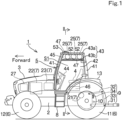
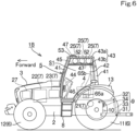
- FIG. 1 is a schematic side view of the agricultural tractor 1 according to the first embodiment of the present invention.
- the tractor 1 in FIG. 1 shows the left side of the entirety of the tractor.
- the tractor 1 in FIG. 1 includes a vehicle body 2 that is long in the front-rear direction; a hood 3 that is provided at a front portion of the vehicle body 2; a cabin 5 that is mounted on a rear portion of the vehicle body 2 to accommodate an operator seat 4 on which an operator is to sit; a wheel-type traveling device 6 that supports the vehicle body 2 to be capable of traveling; a drive 7 that drives the traveling device 6; a three-point linkage 9 that is provided at the rear end of the vehicle body 2; and a PTO shaft (power extraction shaft) 10 that transmits power from the drive 7.
- a PTO shaft power extraction shaft
- the traveling device 6 in FIG. 1 includes a left-right pair of rear wheels 11 and a left-right pair of front wheels 12. An upper portion of each of the rear wheels 11 is covered by a fender 13.
- the traveling device 6 employs a four-wheel drive system of a two-wheel-drive/four-wheel-drive switching type and is switchable between a two-wheel drive state in which only the rear wheels 11 are driven and a four-wheel drive state in which the rear wheels 11 and the front wheels 12 are driven.
- the present invention is also applicable to a tractor that includes a traveling device employing a two-wheel drive system in which only rear wheels are driven or a caterpillar track system (crawler type).
- An input portion of the working device of various types is coupled to a PTO shaft 10 via a drive shaft.
- the PTO shaft 10 is rotated by power transmitted from the drive motor 21.
- the working device is, for example, a cultivator for cultivation, a fertilizer spreader for spreading a fertilizer, an agricultural chemical spreader for spreading an agricultural chemical, a harvester for harvesting, a mower for mowing grass or the like, a tedder for tedding grass or the like, a rake for raking grass or the like, and a baler (roll baler) for baling grass or the like.
- the cabin 5 in FIG. 1 includes four cabin frames (supports) 41 that extend upward from four corners; a transparent wall (no reference sign) that covers the front surface, the right surface, and the rear surface thereof; transparent boarding doors 42 that cover the left and right surfaces thereof; and the ceiling wall 43.
- a steering device 44 including a steering wheel and the like is disposed forward of the operator seat 4, and an air conditioning (air conditioner) unit 46 that performs air-conditioning of the internal space S1 of the cabin 5 is disposed under the operator seat 4.
- At least one boarding step 8 on which an operator places his/her feet when getting on and off the cabin 5 is disposed below the cabin 5.
- the boarding step 8 is provided below each of the boarding doors 42 at the left and the right.
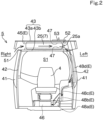
- FIG. 2 is a schematic sectional view taken along line II-II in FIG. 1 and clarifies an arrangement of the hydrogen tanks 25 and a structure of an outside-air introduction path E of the air conditioning unit 46.
- the air conditioning unit 46 has a cooling function, a heating function, and a blowing function.
- the outside-air introduction path E for introducing outside air is connected to the air conditioning unit 46.
- the outside-air introduction path E includes a plurality of ducts 48a, 48b, 48c, and 48d that are connected to extend upward along the left side of the cabin 5 from an introduction port in the left surface of the air conditioning unit 46, and the ceiling space 45 in communication with the upper end of the uppermost duct 48d.
- the ceiling space 45 that houses the hydrogen tanks 25 is used as a guide passage for outside air.
- a right end portion of the ceiling space 45 has an outside-air intake port 51 that opens downward with respect to the outside.
- the air conditioning unit 46 is configured to introduce outside air to the inside of the cabin 5.
- the outside-air intake port 51 for the air conditioning unit 46 is provided in the cabin 5, and the ceiling space (guide passage) 45 in which the outside air that is taken in from the outside-air intake port 51 passes the outer peripheries of the hydrogen tanks 25 is provided. That is, the outside-air introduction path E crosses the ceiling space (guide passage) 45 from the right to the left from the outside-air intake port 51, extends downward from a left end portion of the ceiling space (guide passage) 45 through the plurality of ducts 48d, 48c, and 48b and finally reaches the air conditioning unit 46 via the lowermost duct 48a.
- the hydrogen-gas detector 52 is disposed in the vicinity of caps 25a of the hydrogen tanks 25 and attached to the lower surface of the first wall 43a of the ceiling wall 43.
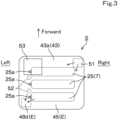
- FIG. 3 is a plan view (top view) of the cabin 5.
- the outside-air intake port 51 is positioned at a right front-end portion of the ceiling wall 43 while the upper end of the uppermost duct 48d is positioned at a left rear-end portion of the ceiling wall 43.
- the sliding-type exhaust door 53 is positioned in the vicinity of the caps 25a of the hydrogen tanks 25.
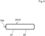
- FIG. 4 is a longitudinal sectional view of the hydrogen tank 25.
- the hydrogen tank 25 has a liner 60 having an internal space filled with the hydrogen gas.
- An outer surface of the liner 60 is covered with a carbon fiber reinforced plastic (CFRP) layer 61.
- the liner 60 accommodates a high-pressure gas, accommodates the hydrogen gas by increasing pressure of the hydrogen gas or cooling the hydrogen gas, and releases the hydrogen gas by decreasing the pressure of the hydrogen gas or heating the hydrogen gas.
- the hydrogen tank 25 is a high-pressure hydrogen tank. With this configuration, it is possible to accommodate a large amount of the hydrogen gas while reducing the weight of the hydrogen tank, which achieves easy handling of the hydrogen tank and a reduction in the weight of a vehicle.
- the fuel cell 22 generates electric power by causing the hydrogen gas supplied from the high-pressure hydrogen tanks 25 to react with air (oxygen) taken in from the outside air.
- air oxygen
- a substance discharged at this time is only water, and harmful substances, such as carbon dioxide, are not discharged.
- Generated DC electric power is converted into AC electric power and subjected to frequency control by the controller 23.
- the AC electric power is supplied to the drive motor 21 and rotates the output shaft of the drive motor 21 at a desired rotational speed.
- the rotational power of the drive motor 21 is transmitted to the axles of the rear wheels 11 indirectly via the transmission mechanism or directly and rotates the rear wheels 11 to cause traveling in, for example, the two-wheel drive state.
- the rotational power is also transmitted to the front wheels 12, as necessary, to cause traveling in the four-wheel drive state. Further, the rotational power is also transmitted to the PTO shaft 10 to drive a working device.
- the air conditioning unit 46 when the air conditioning unit 46 is actuated, the outside air taken in from the outside-air intake port 51 in the ceiling wall 43 is introduced to the air conditioning unit 46 through the outside-air introduction path E.
- the ceiling space 45 housing the hydrogen tanks 25 is used as a guide passage.
- the hydrogen tanks 25 are actively cooled by the outside air passing the peripheries of the hydrogen tanks 25 in the inside of the ceiling space 45. That is, it is possible to suppress a temperature increase of the hydrogen tanks 25.
- the hydrogen-gas detector 52 disposed in the vicinity of the caps 25a of the hydrogen tanks 25 detects the leaked hydrogen gas and immediately opens the exhaust door 53. Accordingly, it is possible to discharge via the exhaust door 53 the leaked hydrogen gas immediately after the hydrogen gas leaks in the inside of the ceiling space 45.
- the hydrogen tanks 25 are disposed in the upper portion of the internal space S1 of the cabin 5, an arrangement space can be easily ensured, and a temperature increase of the hydrogen tanks 25 can be further suppressed compared with, for example, a case in which the hydrogen tanks 25 are accommodated together with a heat generating member such as a fuel cell in the inside of the hood.
- the hydrogen tanks 25 are disposed in the inside of the cabin 5, the hydrogen tanks 25 can be protected also from vibration from the outside and vibration due to a fall and the like of the tractor 1.
- the weight of the hydrogen tank 25 is reduced compared with a conventional high-pressure hydrogen tank. Accordingly, it is possible to house a large amount of the hydrogen gas while reducing the weight of the hydrogen tank 25, which achieves easy handling of the hydrogen tank 25 and a reduction in the weight of a vehicle.
- the hydrogen-gas detector 52 is disposed in the upper portion of the internal space S1 of the cabin 5, even if the hydrogen gas leaks, hydrogen-gas leakage can be detected in an early stage and can be dealt with.
- the exhaust door 53 interlocked with the hydrogen-gas detector 52 is provided in the ceiling wall 43 (first wall 43a), it is possible to automatically open the exhaust door 53 quickly when detecting leaked hydrogen gas and immediately discharge the leaked hydrogen gas upward from the inside of the cabin 5.
- the air conditioning unit 46 that adjusts air in the inside of the cabin 5 is included, it is possible to adjust the temperature at the peripheries of the hydrogen tanks 25 without additionally providing a cooler for the high-pressure hydrogen tanks intentionally. Further, since the outside air taken in from the outside-air intake port 51 in the ceiling wall 43 passes the peripheries of the hydrogen tanks 25 in the inside of the ceiling space (guide passage 45), it is possible to efficiently use the outside air for the air conditioning unit 46 to cool the hydrogen tanks 25.
- the ceiling wall 43 of the cabin 5 has the double structure including the first wall 43a on the upper side and the second wall 43b on the lower side, and the ceiling space 45 between the first wall 43a and the second wall 43b is used as a guide passage for outside-air introduction of the air conditioning unit 46. Accordingly, it is possible to reduce the costs of the vehicle and maintain the compact characteristics since the existing structure is used without additionally providing a guide passage for outside-air introduction of the air conditioning unit 46.
- the hydrogen tanks 25 are disposed in the ceiling space 45 between the first wall 43a and the second wall 43b, the function of protecting the high-pressure hydrogen tanks 25 from external obstacles is improved.
- the exhaust door 53 that is automatically opened when the hydrogen-gas detector 52 detects a certain amount or more of the hydrogen gas.
- the present embodiment is characterized in that a ventilator 63 that performs ventilation of the internal space S1 of the cabin 5 is further provided.
- FIG. 5 is a schematic side view of an agricultural tractor 1A according to the second embodiment of the present invention.
- the tractor 1A in FIG. 5 differs from the tractor 1 in FIG. 1 in that the ventilator 63 is provided at an upper portion of the right side wall of the cabin 5.
- the ventilator 63 in FIG. 5 performs the ventilation of the internal space S1 of the cabin 5 at least while the hydrogen tanks 25 supply the hydrogen gas to the fuel cell 22. With this configuration, an increase in the temperature of the internal space S1 of the cabin 5 can be suppressed, and, eventually, an increase in the temperatures of the hydrogen tanks 25 can be suppressed.
- the ventilator 63 in FIG. 5 includes a fan 63a and a motor 63b. To the motor 63b, electric power is supplied from the fuel cell 22.
- the motor 63b is electrically connected to the controller 23.
- the controller 23 actuates the motor 63b to perform the ventilation of the internal space S1 of the cabin 5.
- the motor 63b is configured to be supplied with electric power from the fuel cell 22, but may be configured such that electric power is supplied to the motor 63b from the battery 27 disposed in the inside of the hood 3.
- the controller 23 is electrically connected to the hydrogen-gas detector 52.
- the controller 23 increases the output of the ventilation of the ventilator 63 by controlling such that the rotation speed of the motor 63b is increased.
- the operation of the tractor 1A according to the second embodiment configured as described above is similar to the operation of the tractor 1 according to the first embodiment.
- FIG. 6 is a schematic side view of an agricultural tractor 1B according to the third embodiment of the present invention.
- the tractor 1B in FIG. 6 differs from the tractor 1 in FIG. 1 in that the ceiling space 45 is used as a cooling passage for cooling air that is delivered from the air conditioning unit 46 to the inside of the cabin 5 in the tractor 1B in FIG. 6 while the ceiling space 45 in FIG. 1 is used as the guide passage for outside-air intake of the air conditioning unit 46.
- the air conditioning unit 46 that generates cooling air and that introduces the cooling air to the inside of the cabin 5 is provided under the operator seat 4.
- the ceiling space 45 of the cabin 5 is used as a cooling passage through which part or entirety of the cooling air generated by the air conditioning unit 46 passes the peripheries of the hydrogen tanks 25. That is, the cabin 5 is provided with a duct 65b that introduces the cooling air or part thereof from a cooling-air introduction port 65a of the air conditioning unit 46 to the ceiling space (cooling passage) 45.
- the operation of the tractor 1B according to the third embodiment configured as described above is similar to the operation of the tractor 1 according to the first embodiment.
- tractor 1B compared with the tractor 1 according to the first embodiment, it is possible to cool the hydrogen tanks 25 without additionally providing cooling equipment since the air conditioning unit 46 for cooling the cabin 5 can be also used to cool the hydrogen tanks 25. Accordingly, it is possible to reduce costs for additionally providing a cooling equipment and possible to improve the cooling effect.
- the working machine 1 is the working machine 1 that includes the vehicle body 2; the traveling device 6 that supports the vehicle body 2; the drive 7 that drives the traveling device 6; and the cabin 5 that accommodates the operator seat 4.
- the drive 7 has the drive motor 21 that drives the traveling device 6; the fuel cell 22 that supplies electric power to the drive motor 21; the controller 23 that controls power supply from the fuel cell 22 to the drive motor 21; and the hydrogen tanks 25 that supply the hydrogen gas for fuel to the fuel cell 22.
- the hydrogen tanks 25 are disposed in the upper portion of the internal space S1 of the cabin 5.
- the working machine 1 further includes the hydrogen-gas detection portion 52 that detects the hydrogen gas.
- the hydrogen-gas detection portion 52 is disposed in the upper portion of the internal space S1 of the cabin 5.
- the hydrogen-gas detection portion 52 is disposed at the upper portion of the internal space S1 of the cabin 5, even if the hydrogen gas leaks, the leakage of the hydrogen gas can be detected in an early stage and can be dealt with.
- the ceiling wall 43 of the cabin 5 is further provided with the exhaust door 53 that is opened when the hydrogen-gas detection portion 52 detects the hydrogen gas and that causes the internal space S1 of the cabin 5 and the outside to be in communication with each other.
- the cabin 5 is further provided with the ventilator 63 that performs ventilation of the internal space S1 of the cabin 5.
- the ventilator 63 performs the ventilation at least while the hydrogen tanks 25 supply the hydrogen gas to the fuel cell 22.
- the working machine 1 further includes the hydrogen-gas detection portion 52 that detects the hydrogen gas.
- the ventilator 63 increases the output of the ventilation when the hydrogen-gas detection portion 52 detects the hydrogen gas.
- the working machine 1 further includes the air conditioning unit 46 that generates cooling air and that introduces the cooling air to the inside of the cabin 5.
- the cabin 5 is provided with the cooling passage through which the cooling air introduced from the air conditioning unit 46 passes the outer peripheries of the hydrogen tanks 25.
- the working machine 1 further includes the air conditioning unit 46 that introduces outside air to the inside of the cabin 5.
- the outside-air intake port 51 for the air conditioning unit 46 is provided in the cabin 5, and the guide passage 45 through which the outside air taken in from the outside-air intake port 51 passes the outer peripheries of the hydrogen tanks 25 is provided.
- the ceiling wall 43 of the cabin 5 has the double structure including the first wall 43a on the upper side and the second wall 43b on the lower side, and the guide passage 45 is formed by the space defined by the first wall 43a and the second wall 43b.
- the ceiling wall 43 of the cabin 5 has the double structure including the first wall 43a on the upper side and the second wall 43b on the lower side, and the ceiling space between the first wall 43a and the second wall 43b is used as the guide passage 45 for outside-air introduction of the air conditioning unit 46. Accordingly, it is possible to reduce the costs of the vehicle and maintain the compact characteristics since the existing structure is used, without additionally providing the guide passage 45 for outside-air introduction of the air conditioning unit 46.
- the ceiling wall 43 of the cabin 5 has the double structure including the first wall 43a on the upper side and the second wall 43b on the lower side, and the hydrogen tanks 25 are disposed in the space defined by the first wall 43a and the second wall 43b.
- the working machine 1 further includes the housing case 70 that houses the hydrogen tank 25, and the housing case 70 stores water that cools the hydrogen tank 25.
- the working machine 1 further includes the housing case 70 that houses the hydrogen tank 25, and the hydrogen tank 25 is installed via the vibration absorbing members 71 with respect to the placement surface formed in the inside of the housing case 70.
- the hydrogen tank 25 has the liner having the internal space S1 filled with the hydrogen gas, and the outer surface of the liner is covered with the carbon fiber reinforced plastic layer 61.
Landscapes
- Engineering & Computer Science (AREA)
- Life Sciences & Earth Sciences (AREA)
- Sustainable Development (AREA)
- Sustainable Energy (AREA)
- Mechanical Engineering (AREA)
- Transportation (AREA)
- Chemical & Material Sciences (AREA)
- Combustion & Propulsion (AREA)
- Power Engineering (AREA)
- General Engineering & Computer Science (AREA)
- Cooling, Air Intake And Gas Exhaust, And Fuel Tank Arrangements In Propulsion Units (AREA)
- Arrangement Or Mounting Of Propulsion Units For Vehicles (AREA)
Applications Claiming Priority (2)
| Application Number | Priority Date | Filing Date | Title |
|---|---|---|---|
| JP2021117177A JP7597664B2 (ja) | 2021-07-15 | 2021-07-15 | 農業用トラクタ |
| EP22179424.1A EP4119379B1 (fr) | 2021-07-15 | 2022-06-16 | Machine de travail |
Related Parent Applications (2)
| Application Number | Title | Priority Date | Filing Date |
|---|---|---|---|
| EP22179424.1A Division-Into EP4119379B1 (fr) | 2021-07-15 | 2022-06-16 | Machine de travail |
| EP22179424.1A Division EP4119379B1 (fr) | 2021-07-15 | 2022-06-16 | Machine de travail |
Publications (2)
| Publication Number | Publication Date |
|---|---|
| EP4390208A2 true EP4390208A2 (fr) | 2024-06-26 |
| EP4390208A3 EP4390208A3 (fr) | 2024-11-13 |
Family
ID=82399579
Family Applications (2)
| Application Number | Title | Priority Date | Filing Date |
|---|---|---|---|
| EP24174643.7A Withdrawn EP4390208A3 (fr) | 2021-07-15 | 2022-06-16 | Machine de travail |
| EP22179424.1A Active EP4119379B1 (fr) | 2021-07-15 | 2022-06-16 | Machine de travail |
Family Applications After (1)
| Application Number | Title | Priority Date | Filing Date |
|---|---|---|---|
| EP22179424.1A Active EP4119379B1 (fr) | 2021-07-15 | 2022-06-16 | Machine de travail |
Country Status (3)
| Country | Link |
|---|---|
| US (1) | US12330517B2 (fr) |
| EP (2) | EP4390208A3 (fr) |
| JP (2) | JP7597664B2 (fr) |
Families Citing this family (27)
| Publication number | Priority date | Publication date | Assignee | Title |
|---|---|---|---|---|
| CN114616169B (zh) * | 2019-11-01 | 2024-07-30 | 沃尔沃卡车集团 | 具有用于氢储存的后壁的卡车 |
| DE102021130374A1 (de) * | 2021-11-19 | 2023-05-25 | Liebherr-Werk Bischofshofen Gmbh | Arbeitsmaschine |
| CN119451887A (zh) * | 2022-06-28 | 2025-02-14 | 株式会社久保田 | 农业拖拉机 |
| CN119497679A (zh) * | 2022-06-28 | 2025-02-21 | 株式会社久保田 | 作业车辆、作业车辆的控制装置及控制方法 |
| CN119451840A (zh) * | 2022-06-28 | 2025-02-14 | 株式会社久保田 | 作业车辆 |
| JP7788980B2 (ja) * | 2022-09-26 | 2025-12-19 | 株式会社クボタ | 作業車 |
| GB202216969D0 (en) * | 2022-11-14 | 2022-12-28 | Vantastec Ltd | Vehicle comprising an electrical power generating system |
| GB2625057B (en) * | 2022-12-01 | 2025-06-18 | Bamford Excavators Ltd | A gaseous fuel storage system for a working machine |
| GB2625060B (en) * | 2022-12-01 | 2025-03-05 | Bamford Excavators Ltd | A storage system for a gaseous fuel |
| GB2625059B (en) * | 2022-12-01 | 2025-06-25 | Bamford Excavators Ltd | A gaseous fuel storage system for a working machine |
| GB2631275B (en) * | 2023-06-22 | 2026-03-25 | Caterpillar Inc | Power module for work machine |
| WO2025004682A1 (fr) * | 2023-06-30 | 2025-01-02 | 株式会社クボタ | Véhicule de travail |
| JPWO2025004578A1 (fr) | 2023-06-30 | 2025-01-02 | ||
| EP4737169A1 (fr) | 2023-06-30 | 2026-05-06 | Kubota Corporation | Véhicule de chantier |
| EP4737170A1 (fr) | 2023-06-30 | 2026-05-06 | Kubota Corporation | Véhicule de chantier |
| EP4737177A1 (fr) | 2023-06-30 | 2026-05-06 | Kubota Corporation | Véhicule de travail |
| EP4737178A1 (fr) * | 2023-06-30 | 2026-05-06 | Kubota Corporation | Véhicule de travail |
| WO2025013632A1 (fr) * | 2023-07-07 | 2025-01-16 | コベルコ建機株式会社 | Machine de travail |
| KR102732741B1 (ko) * | 2023-11-07 | 2024-11-20 | 건설기계부품연구원 | 특수목적용 수소모빌리티의 수소 저장 및 관리장치 |
| JP2025101945A (ja) * | 2023-12-26 | 2025-07-08 | 株式会社クボタ | 作業車両 |
| WO2025142005A1 (fr) * | 2023-12-26 | 2025-07-03 | 株式会社クボタ | Engin de chantier |
| WO2025142002A1 (fr) * | 2023-12-26 | 2025-07-03 | 株式会社クボタ | Engin de chantier et véhicule de chantier |
| WO2025142043A1 (fr) * | 2023-12-26 | 2025-07-03 | 株式会社クボタ | Véhicule de travail |
| JP2025101932A (ja) * | 2023-12-26 | 2025-07-08 | 株式会社クボタ | 作業車両 |
| JP2025141357A (ja) * | 2024-03-15 | 2025-09-29 | 株式会社クボタ | 作業車両 |
| JP2025141352A (ja) * | 2024-03-15 | 2025-09-29 | 株式会社クボタ | 作業車両 |
| JP2025141358A (ja) * | 2024-03-15 | 2025-09-29 | 株式会社クボタ | 作業車両 |
Citations (2)
| Publication number | Priority date | Publication date | Assignee | Title |
|---|---|---|---|---|
| JP2010023550A (ja) | 2008-07-15 | 2010-02-04 | Honda Motor Co Ltd | 車両 |
| JP2021000899A (ja) | 2019-06-21 | 2021-01-07 | 株式会社クボタ | 作業車 |
Family Cites Families (23)
| Publication number | Priority date | Publication date | Assignee | Title |
|---|---|---|---|---|
| JPH0725225A (ja) * | 1993-07-12 | 1995-01-27 | Mitsubishi Motors Corp | 車両用空調装置 |
| JP2003149071A (ja) | 2001-11-14 | 2003-05-21 | Toyota Motor Corp | 移動体における有害ガス漏れ検出装置 |
| KR100461150B1 (ko) | 2002-02-07 | 2004-12-13 | 현대자동차주식회사 | 연료전지 차량의 수소저장탱크 냉각시스템 |
| JP4590833B2 (ja) | 2003-07-24 | 2010-12-01 | トヨタ自動車株式会社 | 冷却システムを備える移動体 |
| JP4114589B2 (ja) | 2003-10-22 | 2008-07-09 | 株式会社デンソー | 車両用空調装置 |
| DE10350177A1 (de) * | 2003-10-28 | 2005-06-16 | Webasto Ag | Dachmodul |
| JP5024588B2 (ja) * | 2005-12-12 | 2012-09-12 | トヨタ自動車株式会社 | 燃料電池車両 |
| DE102007006047B4 (de) | 2007-02-02 | 2008-10-30 | Mizu Vertriebs-Gmbh | Schutzeinrichtung für Gasbehälter |
| US8302997B2 (en) * | 2010-11-01 | 2012-11-06 | Ford Global Technologies, Llc | Vehicle fuel storage system |
| US9114930B2 (en) * | 2011-03-07 | 2015-08-25 | Casella Waste Systems, Inc. | Compressed natural gas vehicle apparatus and method |
| JP5576328B2 (ja) | 2011-03-30 | 2014-08-20 | 株式会社クボタ | 作業車 |
| KR101302262B1 (ko) | 2011-03-30 | 2013-09-02 | 가부시끼 가이샤 구보다 | 작업차 |
| JP5940891B2 (ja) | 2012-05-29 | 2016-06-29 | 本田技研工業株式会社 | 燃料電池システムの換気方法 |
| BR102014023485B1 (pt) * | 2013-11-01 | 2022-04-12 | Cnh Industrial America Llc | Veículo de trabalho |
| US10486530B2 (en) * | 2015-12-28 | 2019-11-26 | Mark Matijevich | Process for developing fuel systems |
| JP6477575B2 (ja) | 2016-04-19 | 2019-03-06 | トヨタ自動車株式会社 | 周辺情報検出センサの配設構造 |
| WO2018234810A1 (fr) * | 2017-06-23 | 2018-12-27 | J.C. Bamford Excavators Ltd | Système à deux carburants pour véhicules de travail |
| JP7180543B2 (ja) | 2019-06-03 | 2022-11-30 | トヨタ自動車株式会社 | ガス漏れ検知システム |
| CN110217116B (zh) | 2019-06-04 | 2024-10-15 | 武汉海亿新能源科技有限公司 | 一种基于燃料电池的农用拖拉机及其控制方法 |
| CN210149159U (zh) | 2019-06-04 | 2020-03-17 | 武汉海亿新能源科技有限公司 | 一种基于燃料电池的农用拖拉机 |
| JP7392941B2 (ja) | 2019-10-30 | 2023-12-06 | いすゞA&S株式会社 | 空調機 |
| JP7306965B2 (ja) | 2019-11-05 | 2023-07-11 | トヨタ自動車株式会社 | 貨物車両 |
| JP7189112B2 (ja) | 2019-11-05 | 2022-12-13 | トヨタ自動車株式会社 | 貨物車両 |
-
2021
- 2021-07-15 JP JP2021117177A patent/JP7597664B2/ja active Active
-
2022
- 2022-06-14 US US17/840,145 patent/US12330517B2/en active Active
- 2022-06-16 EP EP24174643.7A patent/EP4390208A3/fr not_active Withdrawn
- 2022-06-16 EP EP22179424.1A patent/EP4119379B1/fr active Active
-
2024
- 2024-11-28 JP JP2024207378A patent/JP2025023089A/ja active Pending
Patent Citations (2)
| Publication number | Priority date | Publication date | Assignee | Title |
|---|---|---|---|---|
| JP2010023550A (ja) | 2008-07-15 | 2010-02-04 | Honda Motor Co Ltd | 車両 |
| JP2021000899A (ja) | 2019-06-21 | 2021-01-07 | 株式会社クボタ | 作業車 |
Also Published As
| Publication number | Publication date |
|---|---|
| JP2025023089A (ja) | 2025-02-14 |
| JP2023013186A (ja) | 2023-01-26 |
| EP4119379B1 (fr) | 2024-06-12 |
| EP4390208A3 (fr) | 2024-11-13 |
| US12330517B2 (en) | 2025-06-17 |
| EP4119379A1 (fr) | 2023-01-18 |
| JP7597664B2 (ja) | 2024-12-10 |
| US20230019714A1 (en) | 2023-01-19 |
Similar Documents
| Publication | Publication Date | Title |
|---|---|---|
| EP4119379B1 (fr) | Machine de travail | |
| US8875823B2 (en) | Multi-functional cooling system | |
| KR101397216B1 (ko) | 작업차 | |
| JP7769113B2 (ja) | 作業車両 | |
| JP7833036B2 (ja) | 作業車両 | |
| WO2024004904A1 (fr) | Véhicule de travail | |
| JP2026022653A (ja) | 作業車両 | |
| WO2024004906A1 (fr) | Véhicule de chantier | |
| WO2024004914A1 (fr) | Tracteur agricole | |
| JP7755745B2 (ja) | 作業車両 | |
| WO2024004905A1 (fr) | Véhicule de travail | |
| US20260084521A1 (en) | Work vehicle | |
| JP2023112412A (ja) | 電動作業車 | |
| US20260070424A1 (en) | Work vehicle | |
| JP7801447B2 (ja) | 作業車両 | |
| US20260084547A1 (en) | Work vehicle | |
| CN210212025U (zh) | 作业车辆 | |
| WO2025192595A1 (fr) | Véhicule de travail | |
| JP3563512B2 (ja) | 田植機 | |
| WO2025192598A1 (fr) | Véhicule de travail | |
| WO2025192596A1 (fr) | Véhicule de travail | |
| WO2025192597A1 (fr) | Véhicule de travail | |
| WO2025004670A1 (fr) | Engin de chantier | |
| WO2024143328A1 (fr) | Véhicule de chantier | |
| JP2025152172A (ja) | 作業車両 |
Legal Events
| Date | Code | Title | Description |
|---|---|---|---|
| PUAI | Public reference made under article 153(3) epc to a published international application that has entered the european phase |
Free format text: ORIGINAL CODE: 0009012 |
|
| STAA | Information on the status of an ep patent application or granted ep patent |
Free format text: STATUS: REQUEST FOR EXAMINATION WAS MADE |
|
| 17P | Request for examination filed |
Effective date: 20240507 |
|
| AC | Divisional application: reference to earlier application |
Ref document number: 4119379 Country of ref document: EP Kind code of ref document: P |
|
| AK | Designated contracting states |
Kind code of ref document: A2 Designated state(s): AL AT BE BG CH CY CZ DE DK EE ES FI FR GB GR HR HU IE IS IT LI LT LU LV MC MK MT NL NO PL PT RO RS SE SI SK SM TR |
|
| REG | Reference to a national code |
Ref country code: DE Ref legal event code: R079 Free format text: PREVIOUS MAIN CLASS: F17C0001040000 Ipc: B60K0015063000 |
|
| PUAL | Search report despatched |
Free format text: ORIGINAL CODE: 0009013 |
|
| AK | Designated contracting states |
Kind code of ref document: A3 Designated state(s): AL AT BE BG CH CY CZ DE DK EE ES FI FR GB GR HR HU IE IS IT LI LT LU LV MC MK MT NL NO PL PT RO RS SE SI SK SM TR |
|
| RIC1 | Information provided on ipc code assigned before grant |
Ipc: F17C 1/04 20060101ALI20241009BHEP Ipc: B60K 15/03 20060101ALI20241009BHEP Ipc: B60K 15/07 20060101ALI20241009BHEP Ipc: B60K 15/063 20060101AFI20241009BHEP |
|
| STAA | Information on the status of an ep patent application or granted ep patent |
Free format text: STATUS: THE APPLICATION IS DEEMED TO BE WITHDRAWN |
|
| 18D | Application deemed to be withdrawn |
Effective date: 20250514 |