EP4390218A1 - Fibre optique résistante à la fatigue et résistante à l'irradiation latérale améliorée - Google Patents
Fibre optique résistante à la fatigue et résistante à l'irradiation latérale améliorée Download PDFInfo
- Publication number
- EP4390218A1 EP4390218A1 EP22216668.8A EP22216668A EP4390218A1 EP 4390218 A1 EP4390218 A1 EP 4390218A1 EP 22216668 A EP22216668 A EP 22216668A EP 4390218 A1 EP4390218 A1 EP 4390218A1
- Authority
- EP
- European Patent Office
- Prior art keywords
- optical fiber
- section
- core section
- refractive index
- scattering sites
- Prior art date
- Legal status (The legal status is an assumption and is not a legal conclusion. Google has not performed a legal analysis and makes no representation as to the accuracy of the status listed.)
- Granted
Links
Images




Classifications
-
- G—PHYSICS
- G02—OPTICS
- G02B—OPTICAL ELEMENTS, SYSTEMS OR APPARATUS
- G02B6/00—Light guides; Structural details of arrangements comprising light guides and other optical elements, e.g. couplings
- G02B6/0001—Light guides; Structural details of arrangements comprising light guides and other optical elements, e.g. couplings specially adapted for lighting devices or systems
- G02B6/0005—Light guides; Structural details of arrangements comprising light guides and other optical elements, e.g. couplings specially adapted for lighting devices or systems the light guides being of the fibre type
- G02B6/001—Light guides; Structural details of arrangements comprising light guides and other optical elements, e.g. couplings specially adapted for lighting devices or systems the light guides being of the fibre type the light being emitted along at least a portion of the lateral surface of the fibre
-
- G—PHYSICS
- G02—OPTICS
- G02B—OPTICAL ELEMENTS, SYSTEMS OR APPARATUS
- G02B6/00—Light guides; Structural details of arrangements comprising light guides and other optical elements, e.g. couplings
- G02B6/02—Optical fibres with cladding with or without a coating
- G02B6/036—Optical fibres with cladding with or without a coating core or cladding comprising multiple layers
- G02B6/03605—Highest refractive index not on central axis
- G02B6/03611—Highest index adjacent to central axis region, e.g. annular core, coaxial ring, centreline depression affecting waveguiding
-
- G—PHYSICS
- G02—OPTICS
- G02B—OPTICAL ELEMENTS, SYSTEMS OR APPARATUS
- G02B6/00—Light guides; Structural details of arrangements comprising light guides and other optical elements, e.g. couplings
- G02B6/02—Optical fibres with cladding with or without a coating
- G02B6/02057—Optical fibres with cladding with or without a coating comprising gratings
-
- G—PHYSICS
- G02—OPTICS
- G02B—OPTICAL ELEMENTS, SYSTEMS OR APPARATUS
- G02B6/00—Light guides; Structural details of arrangements comprising light guides and other optical elements, e.g. couplings
- G02B6/02—Optical fibres with cladding with or without a coating
- G02B6/036—Optical fibres with cladding with or without a coating core or cladding comprising multiple layers
- G02B6/03616—Optical fibres characterised both by the number of different refractive index layers around the central core segment, i.e. around the innermost high index core layer, and their relative refractive index difference
- G02B6/03622—Optical fibres characterised both by the number of different refractive index layers around the central core segment, i.e. around the innermost high index core layer, and their relative refractive index difference having 2 layers only
- G02B6/03627—Optical fibres characterised both by the number of different refractive index layers around the central core segment, i.e. around the innermost high index core layer, and their relative refractive index difference having 2 layers only arranged - +
-
- G—PHYSICS
- G02—OPTICS
- G02B—OPTICAL ELEMENTS, SYSTEMS OR APPARATUS
- G02B6/00—Light guides; Structural details of arrangements comprising light guides and other optical elements, e.g. couplings
- G02B6/02—Optical fibres with cladding with or without a coating
- G02B6/036—Optical fibres with cladding with or without a coating core or cladding comprising multiple layers
- G02B6/03616—Optical fibres characterised both by the number of different refractive index layers around the central core segment, i.e. around the innermost high index core layer, and their relative refractive index difference
- G02B6/03638—Optical fibres characterised both by the number of different refractive index layers around the central core segment, i.e. around the innermost high index core layer, and their relative refractive index difference having 3 layers only
- G02B6/0365—Optical fibres characterised both by the number of different refractive index layers around the central core segment, i.e. around the innermost high index core layer, and their relative refractive index difference having 3 layers only arranged - - +
-
- G—PHYSICS
- G02—OPTICS
- G02B—OPTICAL ELEMENTS, SYSTEMS OR APPARATUS
- G02B6/00—Light guides; Structural details of arrangements comprising light guides and other optical elements, e.g. couplings
- G02B6/02—Optical fibres with cladding with or without a coating
- G02B6/036—Optical fibres with cladding with or without a coating core or cladding comprising multiple layers
- G02B6/03616—Optical fibres characterised both by the number of different refractive index layers around the central core segment, i.e. around the innermost high index core layer, and their relative refractive index difference
- G02B6/03661—Optical fibres characterised both by the number of different refractive index layers around the central core segment, i.e. around the innermost high index core layer, and their relative refractive index difference having 4 layers only
- G02B6/03666—Optical fibres characterised both by the number of different refractive index layers around the central core segment, i.e. around the innermost high index core layer, and their relative refractive index difference having 4 layers only arranged - + - +
Definitions
- the invention relates to a strong, fatigue-resistant all-silica optical fiber with enhanced side irradiation and sensing possibility.
- optical fiber side radiation effect The common techniques used to achieve optical fiber side radiation effect are to remove its reflective cladding, micromachine the fiber surface, or taper the fiber tip, ( Hyun Wook Kang, et al. J. Biomed, Optics, 17, 8001-1(2012 ) and van den Bergh et al. US 5,536,265 A (1996 )). Flaws on the fiber surface can and do make such optical fibers in use somewhat more susceptible to mechanical failure due to less strength and greater susceptibility to fatigue. The drop in bending strength is dramatic for such side scattering optical fibers.
- the present invention seeks to provide strong, fatigue-resistant optical fibers with enhanced side irradiation and sensing possibility, and to provide a method for its manufacturing.
- the optical fiber comprises an outer cladding section surrounding an inner core section, the outer cladding section having a refractive index lower than the refractive index of the core section and the outer cladding section and the core section forming an optical light guide.
- the optical fiber further comprises an emission area associated with one emission end of the optical fiber, the emission area extending in the direction of a longitudinal axis of the optical fiber and being arranged for emitting radiation in a lateral direction with respect to the longitudinal axis of the optical fiber, wherein within the emission area, the core section is provided with a plurality of scattering sites, which are each formed by a local variation of the refractive index in the core section.
- the core section surrounds an inner cladding section having an index of refraction lower than the index of refraction of the core section providing a tubular shape of the core section.
- These optical fibers are unique structures, primarily because their inner recesses are a low index, cladding type silica, creating tubular optical fibers with a solid core. Previous tubular optical fibers had been formed from tubular preforms and had only air in the internal section of the fiber. This provided an optical fiber with lower bending strength and nearly twice the surface area, which would be exposed to the environment and its effects on the long-term reliability of the side-illuminating fibers.
- the optical fiber comprises an innermost section having a higher refractive index than the adjacent surrounding section wherein the refractive index of the innermost section and the adjacent surrounding section allow functionality of the innermost section as single or low mode optical waveguide.
- This embodiment provides a means for testing the stress or temperature of the optical fiber in the vicinity of the side irradiating sites thereby providing feedback to the user of the device, providing such localized information using an all-optical sensing system, in particular if the longitudinal innermost section has at least one fiber Bragg grating section in the emission area and can function as a fiberoptic stress and/or /temperature sensor.
- the extension of the scattering sites is bigger in the direction of the longitudinal axis of the optical fiber than in a direction traverse to the longitudinal axis leaving a large portion of the cross section unaffected and thus contributing to the strength of the optical fiber.
- the scattering sites may be distributed within the optical fiber according to various regular patterns providing scattering sites across the total cross section of the core section.
- the scattering sites may be arranged in a circumferential pattern, the diameter of the circumferential pattern varying regularly or irregularly along the longitudinal axis of the optical fiber.
- the scattering sites may in particular arranged in spirals whose rotational symmetry axis is oriented along the longitudinal axis.
- the sections of the optical fiber are preferably made from silica glass, in which scattering sites for optical and infrared radiation can be created.
- the scattering sites are at least at a 75 ⁇ m depth or at least at 200 ⁇ m depth from an outermost silica glass surface and/or at a depth of about 300 ⁇ m or less from the outermost glass surface, providing a bend strength of at least about 0.5 GPa.
- the outermost cladding section may be protected by one or more non-silica protective coating and/or jacket layers contributing to the bend strength of the optical fiber, all of which are removed above the emission area.
- the emission end of the optical fiber may be covered with a reflective coating. This reflective coating directs the non- scattered radiation back into the diffuser, increasing the efficiency of the diffuser.
- a method for manufacturing the optical fiber creates the scattering sites by focusing femtosecond laser pulses at the intended scattering sites. This method allows to create scattering sites deep into the optical fiber.
- the optical fiber may be moved by an xyz positioner while the optical fiber is exposed to the femtosecond laser pulses. This method allows to create complex patterns for the arrangement of the scattering sites that are optimized for efficient and homogenous emission.
- Fig. 1 represents a medical probe 1 having a light diffuser 2 on a distal end 3 of an optical fiber 4. Distal end 3 of medical probe 1 is surrounded by a square, which indicates the boundaries of an enlarged View A which is depicted in Fig. 2 .
- a proximal end 5 of the medical probe 1 is equipped with connector 6 for connecting the optical fiber 4 to a laser, that emits radiation into the optical fiber 4.
- the connector 6 may be provided with a RFID over-sleeve 7 for identifying and administrating the medical probe 1.
- Entire probe length L of the medical probe 1 ranges between about 2 to 6 meters.
- the diffuser 2 is provided with an emission area 8, which varies in length 1 e from 3 to 40 mm, with typical length 1 e of 5 to 30 mm, and distance d of the emission area 8 from distal end 3 is about 1 mm as shown in Fig. 2 .
- the emission area 8 scatters incoming light in lateral direction with respect to a longitudinal axis 9 of the optical fiber 4.
- a reflective coating 10 is deposited at the face of the distal end 3 with the required reflection coefficient at the working wavelength. This reflective coating 10 directs the non-scattered radiation back into the diffuser 2, increasing the efficiency of the medical probe 1.
- the bare silica lengths which is generally somewhat bigger than the length 1 e of the emission area 8, vary between 12 and 50 mm, with typical lengths of 17 to 37 mm.
- the diameter D of a silica surface of the optical fiber 4 is typically from 480 to 960 ⁇ m.
- a length 1 s of an area, in which the secondary jacked is stripped, is typically 20 mm beyond emission area 8.
- outer diameter d pc of primary coating 11 is from 520 to 1100 ⁇ m
- outer diameter d sc of secondary coating 12 is from 600 to 1300 ⁇ m.
- the scattering within the emission area 8 is caused by a plurality of scattering sites 100 located with the emission area 8..
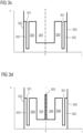
- Fig. 3a to 3d represent possible refractive index profiles of the optical fiber DSc 4, which will be side illuminators of the present disclosure after undergoing the creation of scattering sites 100 as will be explained in more detail below.
- the refractive index profiles of Fig. 3a to 3d show each the refractive index profile along a diameter of the circular cross section of the optical fiber 4.
- Fig. 3a the simplest structure is presented with solid core section 300, surrounded by outer cladding section 301, whose index of refraction is lower than the index of refraction of the core section 300.
- the core section 300 and the outer cladding section 301 which acts as a reflective layer, form a light guide for the radiation emitted by the laser.
- the core section is generally made from undoped silica whereas the outer cladding section is made from fluorine dopes silica.
- a final thin layer of pure silica 302 surrounds the reflective outer cladding section 301
- the optical fiber 4 is further provided with an innermost section 303, which is centered in the optical fiber and represents a low mode core surrounded by a tubular shaped core section 300 with outer cladding section 301 and final layer 302 of pure silica over the outer cladding section 301.
- the innermost section 303 is generally made from silica doped with GeO 2 .
- the innermost section 303 may be a single or low mode core, sometimes called an oligomode or few mode fiber.
- Fiber Bragg Gratings (FBG) may be written into the innermost section 303 to provide stress and/or temperature sensing sites within the innermost section 303. In this case, independent radiation sources for the innermost section 303 and the side radiating core section 300 may be used.
- FBG Fiber Bragg Gratings
- the optical fiber 4 further comprises an inner cladding section 304 surrounded by tubular core section 300 and outer cladding section 301, which typically has the same or lower refractive index comparatively to inner cladding section 304.
- Figure 3d has again an additional high index innermost section 303 within inner cladding section 304 and tubular core section 300.
- an outer silica surface 305 is formed by the outer surface of the final layer 302 but may also be formed by the outer surface of the outer cladding section 301 if the final layer 302 is omitted.
- optical fibers 4 of the present disclosure are drawn from special preforms, which are structured in the following manner.
- a pure silica core rod is used as the starting point for plasma outside vapor deposition, (POVD), of cladding type silica to provide the outer cladding section 30 for generating an optical guide with the desired numerical aperture (NA) and necessary minimal thickness, which will ensure, in the optical fiber 4, no leakage of evanescent waves via outer cladding section 301.
- POVD plasma outside vapor deposition
- NA numerical aperture
- some additional pure silica can be deposited over the outer cladding section 301.
- the draw ratio is chosen to arrive at the desired sizes of the final optical fiber 4 and the various jackets are applied to preserve the inherent strength of the sections with the optical fiber that are made from silica.
- a polyimide jacket is first applied with a Tefzel (DuPont TM) or nylon over jacket.
- a typical optical fiber 4 with the refractive index profile from Figure 3a is designated as OPTRAN ® WF 595 / 630 / 715 // 760 / 900 PT, which means:
- a cladding type silica rod of sufficient thickness for the desired inner final dimension of the inner cladding section 304 of the optical fiber 4 then apply the pure silica for the tubular core section 300 by POVD or a tube sleeving process followed by the addition of another cladding type silica to provide the outer cladding section 301 to the preform, and final outer layer of pure silica at a desired clad/core diameter ratio to complete the preform.
- the protective coatings are added as noted above.
- This example has a refractive index profile as shown in Fig. 3c .
- an innermost core type silica rod can be used for innermost section 303 and cladding type silica is deposited over the rod by a POVD process and then pure silica, which has a higher refractive index is either deposited by POVD or by a tube sleeving process.
- Another section of cladding type silica is deposited over the tubular core section 300 to provide the outer cladding section 301 for generating an optical guide with the desired numerical aperture (NA) and sufficient minimal thickness.
- NA numerical aperture
- Further POVD deposition of extra layer of pure silica allows fine tuning to achieve required overall dimensions.
- the refractive index of such a preform and optical fiber 4 drawn from it is shown in Fig. 3d .
- the core section 300 has an outer diameter from 400 to 800 ⁇ m; the outer silica diameter of the final layer 302 is from 480 to 960 ⁇ m and inner cladding section 304 has an outer diameter from 200 to 450 ⁇ m within tubular core 300.
- innermost part 303 has a diameter from 5 to 21 ⁇ m.
- Figure 4 depicts the setup for creating the scattering sites 100 within the optical fiber 4.
- the optical fiber 4 whose longitudinal axis coincides with a rotary axis 401 is firmly held by adjustable fiber holder 402 and adjustable fiber gripper 403 attached to a three-axis (XYZ) precision positioning stage 404.
- Fiber gripper 403 is able to rotate the optical fiber 4 around the rotary axis 401.
- Femtosecond laser system 405 is positioned with inline attenuator 406 and focusing system 407 to create the scattering sites 100 in the emission area 8.
- Process is monitored by a digital microscope 408, equipped with camera 409, illumination light source 410 and microscope objective 411.
- the optical fiber 4 is translated by the positioning stage 404 and rotated around the rotary axis 401 such that the focus of the laser beam is at the desired position within the optical fiber 4 for generating a scattering site 100 within the core section 300 of the optical fiber 4.
- the density of the silica is changed.
- the laser radiation may even generate void with the silica of the core section 300. In some cases, cracks are formed in the silica.
- optical fibers 4 constructed with refractive index profiles such as Fig. 3a , b; the better and preferred embodiments are fibers whose refractive index profiles follow those of Fig. 3c and 3d , in particular optical fibers 4 having a tubular core section 300. In these optical fibers 4, more of the space of the core section 300 can have scattering sites 100 than in the former case.
- Fiber strength has been found to dramatically depend on distance from scattering defect to the outer silica surface of the optical fiber 4.
- Figure 5 shows this dependency. Choosing 0.5 GPa bend strength as an acceptable minimal strength for practical reasons, Fig. 5 suggests that for a well handleable probes 1, scattering defects for the diffuser 2 should be created at or deeper than 75 • m from an outer silica surface 305 of the optical fiber am 4.
- the attenuation through the silica material also bears on the efficiency of creating inhomogeneities deep within the core section 300 of the optical fiber 4.
- scattering sites 100 could be created up to a depth of 200 to 300 ⁇ m from the outside silica surface 305.
- the scattering sites 100 can be created only in tubular volumes of the optical fiber 4 with depth from 75 ⁇ m to 200-300 ⁇ m, where maximal depth depends on diameter of the optical fiber.
- the scattering sites 100 could not be created inside a central part of the optical fiber 4 with diameters under studies.
- various fiber design were studied for unwanted power, propagated in forward direction.
- the studied designs were the standard fiber design of Fig. 3a and the tubular core design of Figure 3c .
- the results are shown in the table of Fig. 7 .
- Fig. 7 provides evidence of how the tubular core structure enhances the efficiency of side radiation; including the effect of the size of the internal cladding section 304.
- the diameter of the inner cladding section 304 of the EI2 fiber is larger than that of EI1, and length of area of inhomogeneities is 20mm for all fibers.
- a significant amount of light passes the section of inhomogeneities in the standard type core (leftmost column) compared to either size of tubular type core.
- a larger inner cladding section 304 provides for a thinner cross-section of the tubular core section 300, and the efficiency of the side illumination scattering is greater, as seen by the diminished forward power level in the rightmost column.
- the optical fiber 4 having a solid tubular core section 300 are a preferred structure, and most preferred embodiments of the present invention, and are particularly suited to contain a low mode innermost section 303, which can serve as a continuous, all-optical sensor, detecting temperature and/or stress in situ of the side illuminating sections while the probes 1 are in use.
- a very regular and precise pattern of the scattering sites 100 can be introduced along a length of the optical fiber 4. This leads to a more uniform side-irradiation pattern from the optical fiber 4 in use, compared with earlier prior art attempts to provide side illumination of extended areas.
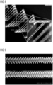
- Fig. 8 shows the scattering sites 100 form five spirals 101 having different diameters but the same pitch. The spirals 101 are aligned along the longitudinal axis 9 of the optical axis.
- the scattering sites 100 here have a 20 ⁇ m length along the longitudinal axis 9 and about a 5 ⁇ m diameter in a direction transverse to the longitudinal axis.
- the scattering sites 100 may vary on their long axis in the range of 13-31 ⁇ m depending on the depth of the site, while the short axis vary in size between around 4 to 6 ⁇ m, and this is independent of depth.
- Section B is an enlarged view of inhomogeneities 100.
- the pitch of the spirals 101 can also vary along the longitudinal axis 9 as can be recognized from Fig. 9 .
- the pitch decreases towards the distal end 3, thus effectively increasing the density of the scattering sites 100 per volume.
- the intensity of the lateral emission may then become more homogenous as the decreasing intensity of the laser radiation towards the distal end 3 is compensated by the increasing density of the scattering sites 100.
- Embodiments of present disclosure provide a tubular core optical fiber with excellent side irradiating ability with a solid innermost section, comprised primarily of low index cladding type glass.
- the low index area, surrounding inner surface of tubular core allows more effective side irradiation of the fiber.
- the optical fiber can also contain an innermost single or low mode core, sometimes called an oligomode or few mode fiber, in which fiber Bragg gratings are written along the optical fiber to provide stress/temperature sensing sites in an innermost core of the side irradiating optical fiber
- This innermost core is positioned in the center of the all-silica optical fiber and serves solely for temperature and stress sensing. Innermost core does not significantly participate in guiding of light power to be scattered in diffusor sections.
- Embodiments of present disclosure create the desired scattering sites within about 75 ⁇ m to 300 ⁇ m of the outermost surface of the outer cladding of the tubular core optical fiber.
- Embodiments of present disclosure use a femtosecond pulse laser to create desired scattering sites within the tubular core to enhance uniform side irradiation in desired portions along the optical fiber.
- a solid, all-silica optical fiber with a tubular core wherein within the core a series of scattering sites have been induced by focusing pulses of a femtosecond, high power density laser at the intended scattering sites.
- the scattering sites are created, generally, at or between 75 ⁇ m and 300 ⁇ m from the outer surface of the outermost cladding of the silica glass.
- Minimal depth of scattering sites defines fiber strength and is the same for fibers with different diameter.
- the optical fiber itself acts as cylindrical lens and this effect defines maximal depth of scattering sites. Maximal depth is mostly defined by fiber diameter. Such fibers have enhanced, uniform side irradiation in use.
- the new enhanced side irradiation optical fibers have a more uniform longitudinal scattered power distribution, do not contain any plastic material in diffusing sections, can simultaneously monitor temperature and stress during operation, are sufficiently mechanically and thermally strong for most applications.
- these new all-silica optical fibers are strong and resist fatigue in use, and the design of tubular core allows efficient side irradiation for fibers with different silica diameters. Bend strength is at least about 0.5 GPa.
- the probes described herein are particularly suited for : Laser Induced Thermal Treatment (LITT) and Photodynamic Therapy (PDT) in a power range of 1 to 10 Watt.
- LITT Laser Induced Thermal Treatment
- PDT Photodynamic Therapy
Landscapes
- Physics & Mathematics (AREA)
- General Physics & Mathematics (AREA)
- Optics & Photonics (AREA)
- Optical Fibers, Optical Fiber Cores, And Optical Fiber Bundles (AREA)
- Light Guides In General And Applications Therefor (AREA)
Priority Applications (4)
| Application Number | Priority Date | Filing Date | Title |
|---|---|---|---|
| EP22216668.8A EP4390218B1 (fr) | 2022-12-23 | 2022-12-23 | Fibre optique résistante à la fatigue et résistante à l'irradiation latérale améliorée |
| CN202380085116.7A CN120303514A (zh) | 2022-12-23 | 2023-12-21 | 具有增强的侧面辐照的强固的抗疲劳光纤 |
| PCT/EP2023/087485 WO2024133816A1 (fr) | 2022-12-23 | 2023-12-21 | Fibre optique résistante à la fatigue et forte à irradiation latérale améliorée |
| JP2025532092A JP2025541777A (ja) | 2022-12-23 | 2023-12-21 | 側面照射が強化された堅牢な耐疲労性光ファイバ |
Applications Claiming Priority (1)
| Application Number | Priority Date | Filing Date | Title |
|---|---|---|---|
| EP22216668.8A EP4390218B1 (fr) | 2022-12-23 | 2022-12-23 | Fibre optique résistante à la fatigue et résistante à l'irradiation latérale améliorée |
Publications (2)
| Publication Number | Publication Date |
|---|---|
| EP4390218A1 true EP4390218A1 (fr) | 2024-06-26 |
| EP4390218B1 EP4390218B1 (fr) | 2026-04-08 |
Family
ID=84604112
Family Applications (1)
| Application Number | Title | Priority Date | Filing Date |
|---|---|---|---|
| EP22216668.8A Active EP4390218B1 (fr) | 2022-12-23 | 2022-12-23 | Fibre optique résistante à la fatigue et résistante à l'irradiation latérale améliorée |
Country Status (4)
| Country | Link |
|---|---|
| EP (1) | EP4390218B1 (fr) |
| JP (1) | JP2025541777A (fr) |
| CN (1) | CN120303514A (fr) |
| WO (1) | WO2024133816A1 (fr) |
Citations (6)
| Publication number | Priority date | Publication date | Assignee | Title |
|---|---|---|---|---|
| US5536265A (en) | 1994-03-25 | 1996-07-16 | Ciba-Geigy Corporation | Light diffuser and process for the manufacturing of a light diffuser |
| US6398778B1 (en) * | 1999-06-18 | 2002-06-04 | Photonics Research Ontario | Optical fiber diffuser |
| US20080158905A1 (en) | 2006-12-29 | 2008-07-03 | Industrial Technology Research Institute | optical fiber and the manufacturing method thereof |
| EP2551706A1 (fr) * | 2010-03-23 | 2013-01-30 | Fujikura, Ltd. | Elément optique du type fibre optique, module à diode laser, et laser à fibre |
| WO2015056220A1 (fr) * | 2013-10-18 | 2015-04-23 | Tissot Yann | Support et systèmes pour éclairage en fonction d'un guide d'ondes |
| US20180113247A1 (en) | 2016-10-25 | 2018-04-26 | Aspyrian Therapeutics Inc. | Cylindrical light diffusing device for use in photoimmunotherapy |
Family Cites Families (3)
| Publication number | Priority date | Publication date | Assignee | Title |
|---|---|---|---|---|
| EP2352046B1 (fr) * | 2010-02-01 | 2018-08-08 | Draka Comteq B.V. | Fibre optique à dispersion décalée non nulle dotée d'une courte longueur d'onde de coupure |
| US20180196191A1 (en) * | 2015-07-10 | 2018-07-12 | 3M Innovative Properties Company | Optical fiber with bragg grating and thin film coating and connector |
| DE102017122756A1 (de) * | 2017-09-29 | 2019-04-04 | Schott Ag | Beleuchtungssystem mit einem Lichtleiter mit Diffusor-Element |
-
2022
- 2022-12-23 EP EP22216668.8A patent/EP4390218B1/fr active Active
-
2023
- 2023-12-21 CN CN202380085116.7A patent/CN120303514A/zh active Pending
- 2023-12-21 JP JP2025532092A patent/JP2025541777A/ja active Pending
- 2023-12-21 WO PCT/EP2023/087485 patent/WO2024133816A1/fr not_active Ceased
Patent Citations (6)
| Publication number | Priority date | Publication date | Assignee | Title |
|---|---|---|---|---|
| US5536265A (en) | 1994-03-25 | 1996-07-16 | Ciba-Geigy Corporation | Light diffuser and process for the manufacturing of a light diffuser |
| US6398778B1 (en) * | 1999-06-18 | 2002-06-04 | Photonics Research Ontario | Optical fiber diffuser |
| US20080158905A1 (en) | 2006-12-29 | 2008-07-03 | Industrial Technology Research Institute | optical fiber and the manufacturing method thereof |
| EP2551706A1 (fr) * | 2010-03-23 | 2013-01-30 | Fujikura, Ltd. | Elément optique du type fibre optique, module à diode laser, et laser à fibre |
| WO2015056220A1 (fr) * | 2013-10-18 | 2015-04-23 | Tissot Yann | Support et systèmes pour éclairage en fonction d'un guide d'ondes |
| US20180113247A1 (en) | 2016-10-25 | 2018-04-26 | Aspyrian Therapeutics Inc. | Cylindrical light diffusing device for use in photoimmunotherapy |
Non-Patent Citations (1)
| Title |
|---|
| HYUN WOOK KANG ET AL., J. BIOMED, OPTICS, vol. 17, 2012, pages 8001 - 1 |
Also Published As
| Publication number | Publication date |
|---|---|
| CN120303514A (zh) | 2025-07-11 |
| JP2025541777A (ja) | 2025-12-23 |
| EP4390218B1 (fr) | 2026-04-08 |
| WO2024133816A1 (fr) | 2024-06-27 |
Similar Documents
| Publication | Publication Date | Title |
|---|---|---|
| US5248311A (en) | Fiber-optic probe for soft-tissue laser surgery | |
| US7317857B2 (en) | Optical fiber for delivering optical energy to or from a work object | |
| US5754717A (en) | Light-diffusing device for an optical fiber, methods of producing and using same, and apparatus for diffusing light from an optical fiber | |
| US20110002584A1 (en) | Annular side fire optical device for laterally redirecting electromagnetic radiation | |
| US20090210038A1 (en) | Medical Light Diffusers for High Power Applications and their Manufacture | |
| US6829411B2 (en) | Wide angle light diffusing optical fiber tip | |
| CN204116658U (zh) | 光纤的涂层去除系统 | |
| US6810184B2 (en) | Device and method to scatter optical fiber output | |
| US6246817B1 (en) | Optical fiber with numerical aperture compression | |
| US20020021869A1 (en) | Optical fiber with numerical aperture compression | |
| CA2265565A1 (fr) | Diffuseur a fibre optique et son procede de production | |
| HK1248824A1 (zh) | 侧向发射的光波导和用於向光波导中引入微修饰的方法 | |
| EP4106696B1 (fr) | Sonde laser à points multiples à fibres multiples mono-coeur | |
| EP0277504B1 (fr) | Structure de l'extrémité d'un faisceau de fibres optiques | |
| EP3653154B1 (fr) | Dispositif de traitement d'un tissu corporel | |
| CN106066511B (zh) | 纤维光学的设备和用于制造这样的设备的方法 | |
| EP4390218B1 (fr) | Fibre optique résistante à la fatigue et résistante à l'irradiation latérale améliorée | |
| KR101259542B1 (ko) | 공공이 부착된 광파이버의 공공 직경의 측정 방법 및 장치와 공공이 부착된 광파이버의 제조 방법 및 장치 | |
| JP2021132754A (ja) | 光ファイバプローブ及び光ファイバプローブの製造方法 | |
| US20250288229A1 (en) | Remote sensing mechanism device | |
| CA2971051A1 (fr) | Fibre optique multicoeur pour detection et sondage repartis multipoints | |
| EP4167001A1 (fr) | Fibre optique multicoeur à partir d'un seul polymère | |
| Inberg et al. | Hollow waveguide for mid and thermal infrared radiation | |
| JP7619593B2 (ja) | 光ファイババンドル及び光ファイババンドル装置 | |
| AU755219B2 (en) | Light-diffusing device for an optical fiber |
Legal Events
| Date | Code | Title | Description |
|---|---|---|---|
| PUAI | Public reference made under article 153(3) epc to a published international application that has entered the european phase |
Free format text: ORIGINAL CODE: 0009012 |
|
| STAA | Information on the status of an ep patent application or granted ep patent |
Free format text: STATUS: THE APPLICATION HAS BEEN PUBLISHED |
|
| AK | Designated contracting states |
Kind code of ref document: A1 Designated state(s): AL AT BE BG CH CY CZ DE DK EE ES FI FR GB GR HR HU IE IS IT LI LT LU LV MC ME MK MT NL NO PL PT RO RS SE SI SK SM TR |
|
| STAA | Information on the status of an ep patent application or granted ep patent |
Free format text: STATUS: REQUEST FOR EXAMINATION WAS MADE |
|
| 17P | Request for examination filed |
Effective date: 20241231 |
|
| RAP1 | Party data changed (applicant data changed or rights of an application transferred) |
Owner name: BIOLITEC HOLDING GMBH & CO KG |
|
| REG | Reference to a national code |
Ref country code: DE Ref legal event code: R079 Free format text: PREVIOUS MAIN CLASS: F21V0008000000 Ipc: G02B0006020000 Ref document number: 602022033955 Country of ref document: DE |
|
| GRAP | Despatch of communication of intention to grant a patent |
Free format text: ORIGINAL CODE: EPIDOSNIGR1 |
|
| STAA | Information on the status of an ep patent application or granted ep patent |
Free format text: STATUS: GRANT OF PATENT IS INTENDED |
|
| RIC1 | Information provided on ipc code assigned before grant |
Ipc: G02B 6/02 20060101AFI20251016BHEP Ipc: F21V 8/00 20060101ALI20251016BHEP Ipc: G02B 6/036 20060101ALI20251016BHEP |
|
| INTG | Intention to grant announced |
Effective date: 20251028 |
|
| RIN1 | Information on inventor provided before grant (corrected) |
Inventor name: NEUBERGER, WOLFGANG Inventor name: GRISCHENKO, ANDREY B. Inventor name: HARSCHACK, ALEXANDER Inventor name: PETROV, PAVEL |
|
| GRAS | Grant fee paid |
Free format text: ORIGINAL CODE: EPIDOSNIGR3 |
|
| GRAA | (expected) grant |
Free format text: ORIGINAL CODE: 0009210 |
|
| STAA | Information on the status of an ep patent application or granted ep patent |
Free format text: STATUS: THE PATENT HAS BEEN GRANTED |
|
| AK | Designated contracting states |
Kind code of ref document: B1 Designated state(s): AL AT BE BG CH CY CZ DE DK EE ES FI FR GB GR HR HU IE IS IT LI LT LU LV MC ME MK MT NL NO PL PT RO RS SE SI SK SM TR |
|
| REG | Reference to a national code |
Ref country code: CH Ref legal event code: F10 Free format text: ST27 STATUS EVENT CODE: U-0-0-F10-F00 (AS PROVIDED BY THE NATIONAL OFFICE) Effective date: 20260408 Ref country code: GB Ref legal event code: FG4D |
|
| REG | Reference to a national code |
Ref country code: DE Ref legal event code: R096 Ref document number: 602022033955 Country of ref document: DE |