EP4390258A1 - Climatiseur - Google Patents
Climatiseur Download PDFInfo
- Publication number
- EP4390258A1 EP4390258A1 EP22858205.2A EP22858205A EP4390258A1 EP 4390258 A1 EP4390258 A1 EP 4390258A1 EP 22858205 A EP22858205 A EP 22858205A EP 4390258 A1 EP4390258 A1 EP 4390258A1
- Authority
- EP
- European Patent Office
- Prior art keywords
- refrigerant
- detection sensor
- refrigerant detection
- sensor
- unit
- Prior art date
- Legal status (The legal status is an assumption and is not a legal conclusion. Google has not performed a legal analysis and makes no representation as to the accuracy of the status listed.)
- Pending
Links
Images


Classifications
-
- F—MECHANICAL ENGINEERING; LIGHTING; HEATING; WEAPONS; BLASTING
- F24—HEATING; RANGES; VENTILATING
- F24F—AIR-CONDITIONING; AIR-HUMIDIFICATION; VENTILATION; USE OF AIR CURRENTS FOR SCREENING
- F24F11/00—Control or safety arrangements
- F24F11/30—Control or safety arrangements for purposes related to the operation of the system, e.g. for safety or monitoring
- F24F11/32—Responding to malfunctions or emergencies
- F24F11/36—Responding to malfunctions or emergencies to leakage of heat-exchange fluid
-
- F—MECHANICAL ENGINEERING; LIGHTING; HEATING; WEAPONS; BLASTING
- F24—HEATING; RANGES; VENTILATING
- F24F—AIR-CONDITIONING; AIR-HUMIDIFICATION; VENTILATION; USE OF AIR CURRENTS FOR SCREENING
- F24F11/00—Control or safety arrangements
- F24F11/30—Control or safety arrangements for purposes related to the operation of the system, e.g. for safety or monitoring
- F24F11/32—Responding to malfunctions or emergencies
-
- F—MECHANICAL ENGINEERING; LIGHTING; HEATING; WEAPONS; BLASTING
- F24—HEATING; RANGES; VENTILATING
- F24F—AIR-CONDITIONING; AIR-HUMIDIFICATION; VENTILATION; USE OF AIR CURRENTS FOR SCREENING
- F24F11/00—Control or safety arrangements
- F24F11/30—Control or safety arrangements for purposes related to the operation of the system, e.g. for safety or monitoring
- F24F11/32—Responding to malfunctions or emergencies
- F24F11/38—Failure diagnosis
-
- F—MECHANICAL ENGINEERING; LIGHTING; HEATING; WEAPONS; BLASTING
- F24—HEATING; RANGES; VENTILATING
- F24F—AIR-CONDITIONING; AIR-HUMIDIFICATION; VENTILATION; USE OF AIR CURRENTS FOR SCREENING
- F24F11/00—Control or safety arrangements
- F24F11/30—Control or safety arrangements for purposes related to the operation of the system, e.g. for safety or monitoring
- F24F11/49—Control or safety arrangements for purposes related to the operation of the system, e.g. for safety or monitoring ensuring correct operation, e.g. by trial operation or configuration checks
-
- F—MECHANICAL ENGINEERING; LIGHTING; HEATING; WEAPONS; BLASTING
- F24—HEATING; RANGES; VENTILATING
- F24F—AIR-CONDITIONING; AIR-HUMIDIFICATION; VENTILATION; USE OF AIR CURRENTS FOR SCREENING
- F24F11/00—Control or safety arrangements
- F24F11/70—Control systems characterised by their outputs; Constructional details thereof
- F24F11/80—Control systems characterised by their outputs; Constructional details thereof for controlling the temperature of the supplied air
- F24F11/83—Control systems characterised by their outputs; Constructional details thereof for controlling the temperature of the supplied air by controlling the supply of heat-exchange fluids to heat-exchangers
- F24F11/84—Control systems characterised by their outputs; Constructional details thereof for controlling the temperature of the supplied air by controlling the supply of heat-exchange fluids to heat-exchangers using valves
-
- F—MECHANICAL ENGINEERING; LIGHTING; HEATING; WEAPONS; BLASTING
- F24—HEATING; RANGES; VENTILATING
- F24F—AIR-CONDITIONING; AIR-HUMIDIFICATION; VENTILATION; USE OF AIR CURRENTS FOR SCREENING
- F24F11/00—Control or safety arrangements
- F24F11/89—Arrangement or mounting of control or safety devices
-
- F—MECHANICAL ENGINEERING; LIGHTING; HEATING; WEAPONS; BLASTING
- F25—REFRIGERATION OR COOLING; COMBINED HEATING AND REFRIGERATION SYSTEMS; HEAT PUMP SYSTEMS; MANUFACTURE OR STORAGE OF ICE; LIQUEFACTION SOLIDIFICATION OF GASES
- F25B—REFRIGERATION MACHINES, PLANTS OR SYSTEMS; COMBINED HEATING AND REFRIGERATION SYSTEMS; HEAT PUMP SYSTEMS
- F25B13/00—Compression machines, plants or systems, with reversible cycle
-
- F—MECHANICAL ENGINEERING; LIGHTING; HEATING; WEAPONS; BLASTING
- F25—REFRIGERATION OR COOLING; COMBINED HEATING AND REFRIGERATION SYSTEMS; HEAT PUMP SYSTEMS; MANUFACTURE OR STORAGE OF ICE; LIQUEFACTION SOLIDIFICATION OF GASES
- F25B—REFRIGERATION MACHINES, PLANTS OR SYSTEMS; COMBINED HEATING AND REFRIGERATION SYSTEMS; HEAT PUMP SYSTEMS
- F25B41/00—Fluid-circulation arrangements
- F25B41/20—Disposition of valves, e.g. of on-off valves or flow control valves
-
- F—MECHANICAL ENGINEERING; LIGHTING; HEATING; WEAPONS; BLASTING
- F25—REFRIGERATION OR COOLING; COMBINED HEATING AND REFRIGERATION SYSTEMS; HEAT PUMP SYSTEMS; MANUFACTURE OR STORAGE OF ICE; LIQUEFACTION SOLIDIFICATION OF GASES
- F25B—REFRIGERATION MACHINES, PLANTS OR SYSTEMS; COMBINED HEATING AND REFRIGERATION SYSTEMS; HEAT PUMP SYSTEMS
- F25B49/00—Arrangement or mounting of control or safety devices
- F25B49/005—Arrangement or mounting of control or safety devices of safety devices
-
- F—MECHANICAL ENGINEERING; LIGHTING; HEATING; WEAPONS; BLASTING
- F25—REFRIGERATION OR COOLING; COMBINED HEATING AND REFRIGERATION SYSTEMS; HEAT PUMP SYSTEMS; MANUFACTURE OR STORAGE OF ICE; LIQUEFACTION SOLIDIFICATION OF GASES
- F25B—REFRIGERATION MACHINES, PLANTS OR SYSTEMS; COMBINED HEATING AND REFRIGERATION SYSTEMS; HEAT PUMP SYSTEMS
- F25B49/00—Arrangement or mounting of control or safety devices
- F25B49/02—Arrangement or mounting of control or safety devices for compression type machines, plants or systems
Definitions
- the present disclosure relates to an air conditioner.
- PTL 1 discloses an air conditioner including a detection sensor that detects concentration of a refrigerant.
- PTL 1 describes a configuration in which a plurality of refrigerant detection sensors for detecting leakage of a flammable refrigerant is provided at the same location. In such a configuration, one of two refrigerant detection sensors having a relatively short lifetime is used, and when the refrigerant detection sensor in use fails, the other refrigerant detection sensor is used. This extends the lifetime of a refrigerant detection sensor (see, for example, PTL 1).
- the present disclosure provides an air conditioner that suppresses degradation in performance of a refrigerant detection sensor caused by aging and improves safety against refrigerant leakage.
- An air conditioner of the present disclosure is an air conditioner in which an indoor heat exchanger included in an indoor unit, and an outdoor heat exchanger, a compressor, and a throttle device included in an outdoor unit are connected via a refrigerant pipe and a flammable refrigerant is used as a refrigerant.
- the air conditioner includes a first refrigerant detection sensor and a second refrigerant detection sensor that detect refrigerant leakage.
- the second refrigerant detection sensor is provided with an external air blocking unit that blocks external air coming to a sensor of the second refrigerant detection sensor, and a release unit that releases the blocking of external air by external air blocking unit.
- the external air blocking unit blocks the external air, thereby suppressing degradation of the second refrigerant detection sensor caused by aging. Safety against refrigerant leakage can thus be improved.
- the present disclosure provides an air conditioner that can suppress degradation of performance of a refrigerant detection sensor caused by aging and improve safety against refrigerant leakage.
- Fig. 1 is a cross-sectional view illustrating an indoor unit of an air conditioner according to the first exemplary embodiment.
- Fig. 3 is a block diagram of a control configuration of air conditioner 1 according to the first exemplary embodiment.
- air conditioner 1 includes indoor unit 10.
- Indoor unit 10 has a configuration illustrated in a cross-sectional view in Fig. 1 .
- Indoor unit 10 includes housing 11 attached to an indoor wall surface.
- Air inlet 12 for sucking indoor air is provided on an upper surface of housing 11.
- Air outlet 13 through which air is blown into an interior is provided on a lower surface of housing 11. Both air inlet 12 and air outlet 13 are formed entirely across the width direction of housing 11.
- Indoor heat exchanger 14 is accommodated in housing 11. Indoor heat exchanger 14 is formed in a substantially inverted V shape in a side view. Indoor heat exchanger 14 is disposed so as to partition a space between air inlet 12 and air outlet 13 in housing 11. Accordingly, the indoor air sucked from air inlet 12 inevitably passes through indoor heat exchanger 14 to reach air outlet 13.
- Indoor air blower 15 is disposed in the inner side of indoor heat exchanger 14. Indoor air blower 15 is rotatably driven by an air blower drive motor (not illustrated) to suck indoor air from air inlet 12 and to blow out the air that has passed through indoor heat exchanger 14 and is thereby subjected to heat exchange into the interior from air outlet 13.
- an air blower drive motor not illustrated
- Filter 16 is disposed at air inlet 12.
- Filter 16 is made of a flexible material, and removes dust and the like in the air sucked from air inlet 12.
- Cleaning drive roller 17 is provided in a front portion of the filter 16 to be rotatably driven. Cleaning drive roller 17 is rotationally driven to wind up filter 16 to clean off dust or the like attached to filter 16.
- Left-right wind direction plate 18 for adjusting the left-right wind direction of blown-out air is provided near air outlet 13 to be swingable in the left-right direction.
- Left-right wind direction plate 18 allows manual adjustment of the wind direction.
- Up-down wind direction plate 19 for adjusting the up-down wind direction of blown-out air is swingably provided below left-right wind direction plate 18. Up-down wind direction plate 19 allows automatic adjustment of the up-down wind direction by a wind direction plate drive motor (not illustrated).
- air conditioner 1 includes outdoor unit 30.
- Outdoor unit 30 includes compressor 31, an outdoor heat exchanger (not illustrated), outdoor air blower 32 that sends external air to the outdoor heat exchanger, expansion mechanism (throttle device) 33, and four-way valve 34.
- Outdoor unit 30 and indoor unit 10 are connected by refrigerant pipe 21 (see Fig. 1 ) to constitute a predetermined refrigeration cycle circuit.
- a flammable refrigerant is used as a refrigerant that circulates in the refrigeration cycle circuit.
- indoor unit 10 includes refrigerant shutoff valve 20.
- Refrigerant shutoff valve 20 performs a closing operation to shut off the refrigerant flowing in refrigerant pipe 21 when refrigerant leakage occurs in indoor unit 10.
- Refrigerant shutoff valve 20 may be installed in outdoor unit 30.
- First refrigerant detection sensor 40 and second refrigerant detection sensor 41 are disposed in housing 11 to be near indoor heat exchanger 14.
- First refrigerant detection sensor 40 is a sensor used from the start of use of indoor unit 10
- second refrigerant detection sensor 41 is a sensor used when first refrigerant detection sensor 40 becomes unusable.
- first refrigerant detection sensor 40 is disposed near a connection between refrigerant pipe 21, connecting outdoor unit 30 and indoor unit 10, and indoor unit 10. This is because, in the initial stage of use of the indoor unit 10, refrigerant leakage is more likely to occur at the connection point between indoor heat exchanger 14 and refrigerant pipe 21 than at other places.
- Second refrigerant detection sensor 41 is disposed near a bending position where refrigerant pipe 21 in indoor heat exchanger 14 turns around. This is because the bending position is where refrigerant leakage due to degradation caused by aging of refrigerant pipe 21 of indoor heat exchanger 14 is likely to occur.
- first refrigerant detection sensor 40 can detect refrigerant leakage at the initial use of indoor unit 10
- second refrigerant detection sensor 41 can detect refrigerant leakage due to degradation of indoor unit 10 caused by aging.
- Second refrigerant detection sensor 41 may be installed at the same location as first refrigerant detection sensor 40. In this case, when first refrigerant detection sensor 40 becomes unusable and detection of refrigerant leakage is switched to that by second refrigerant detection sensor 41, detection of refrigerant leakage can be performed by second refrigerant detection sensor 41 under the same condition as that of first refrigerant detection sensor 40. This suppresses happening of a detection error due to the difference between locations of installation.
- the same location means that locations are within such a range that the surrounding conditions of first refrigerant detection sensor 40 and second refrigerant detection sensor 41 are the same so that refrigerant leakage can be detected under the same condition by first refrigerant detection sensor 40 and second refrigerant detection sensor 41.
- Fig. 2 is a configuration diagram illustrating a schematic configuration of first refrigerant detection sensor 40 and second refrigerant detection sensor 41.
- each of first refrigerant detection sensor 40 and second refrigerant detection sensor 41 includes predetermined sensor board 42.
- Sensor 42a including a semiconductor is mounted on sensor board 42.
- Substantially cylindrical sensor case 43 covering sensor 42a is attached so as to encircle sensor 42a.
- Mesh-liked opening 44 is formed at a distal end of sensor case 43. This allows sensor 42a to detect leaked refrigerant that has entered from opening 44.
- a heater (not illustrated) is disposed near sensor 42a.
- Second refrigerant detection sensor 41 includes external air blocking unit 45 that closes opening 44.
- External air blocking unit 45 includes, for example, lid member 46 that closes opening 44, elastic member 47 such as a spring that biases lid member 46 and opening 44 to separate lid member 46 and opening 44 from each other, and a lid holding member (not illustrated) that holds lid member 46 so as lid member 46 to close opening 44.
- External air blocking unit 45 includes a release unit (releasing mechanism) 48 that releases external air blocking unit 45.
- the present exemplary embodiment illustrates a structure in which the lid holding member of external air blocking unit 45 keeps lid member 46 to be held on sensor case 43.
- the lid holding member holds lid member 46 on sensor case 43 by, for example, a resin that melts at a predetermined temperature.
- release unit 48 includes a heater or the like that melts the resin.
- release unit 48 includes a solenoid or the like that electrically releases the engagement of the holding claw.
- release unit 48 for example, a structure in which no elastic member 47 is provided and lid member 46 is electrically openable may be adopted.
- lid member 46 is made of shape-memory metal that remembers the state in which lid member 46 and opening 44 are separated from each other, and opening 44 is opened by heating lid member 46 to deform by release unit 48 such as a heater.
- lid member 46 moves by the elastic force of elastic member 47 to a place remote from sensor case 43. Accordingly, refrigerant leakage can be detected through opening 44 of sensor case 43.
- External air blocking unit 45 may include a moisture-proof material in the inner side of lid member 46. With this, moisture that may promote degradation of second refrigerant detection sensor 41 in a non-use state can be removed. Degradation of second refrigerant detection sensor 41 can thus be suppressed.
- Lid member 46 of external air blocking unit 45 may be made of a material that shields light and heat. With this, light and heat that may promote degradation of second refrigerant detection sensor 41 in a non-use state can be shielded. Degradation of second refrigerant detection sensor 41 can thus be suppressed.
- Fig. 3 is a block diagram illustrating the control configuration of the present exemplary embodiment.
- indoor unit 10 includes controller 50.
- Controller 50 controls devices of air conditioner 1.
- Controller 50 includes a processor and a memory. The control by controller 50 is performed by the processor executing a program stored in the memory.
- the controller includes timer 51.
- First refrigerant detection sensor 40 and second refrigerant detection sensor 41 are connected to controller 50.
- Controller 50 includes communication unit 52.
- Communication unit 52 can communicate with remote controller 53 operated by a user. That is, by the user operating remote controller 53, controller 50 controls the driving of compressor 31, outdoor air blower 32, expansion mechanism 33, and four-way valve 34 of outdoor unit 30, and of indoor air blower 15 and up-down wind direction plate 19 of indoor unit 10 based on a set temperature input from remote controller 53.
- Controller 50 controls refrigerant shutoff valve 20 to perform a closing operation when first refrigerant detection sensor 40 or second refrigerant detection sensor 41 detects refrigerant leakage.
- Controller 50 counts the drive time of first refrigerant detection sensor 40 by timer 51 of controller 50. For example, controller 50 counts the drive time of first refrigerant detection sensor 40 until the drive time reaches five years, which is the lifetime of first refrigerant detection sensor 40. When the drive time of first refrigerant detection sensor 40 reaches five years, controller 50 drives release unit 48 to release lid member 46. This enables second refrigerant detection sensor 41 to detect refrigerant leakage.
- Controller 50 determines degradation of first refrigerant detection sensor 40 based on the output of first refrigerant detection sensor 40.
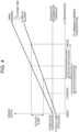
- Fig. 4 is a chart illustrating an example of degradation determination of first refrigerant detection sensor 40.
- the sensor output increases in proportion to the concentration of refrigerant from 0 point.
- controller 50 activates an alarm indicating refrigerant leakage when the sensor output takes a value corresponding to a leaked refrigerant concentration from 1/100 LFL (LFL: minimum flammability concentration) to 1/4 LFL.
- controller 50 performs degradation determination using a degradation determination threshold set for the sensor output at 0 point. Specifically, for example, controller 50 determines that the sensor has degraded when the sensor output at 0 point exceeds the degradation determination threshold and the sensor output continues to exceed the degradation determination threshold for a predetermined time or more, for example, 24 hours or more. The reason why the sensor is determined to be degraded when the sensor output continues to exceed the degradation determination threshold for a predetermined time or more (for example, 24 hours or more) is explained below. The sensor output changes by some degree due to a daily temperature cycle, but it is considered that the sensor output continuously exceeding the degradation determination threshold for 24 hours is not due to the effect of the daily temperature cycle.
- the degradation determination threshold for determining degradation of the sensor is set to a value lower than a sensor output at which the alarm of refrigerant leakage is activated. With this setting, an erroneous alarm activation made by the rise of the sensor output due to degradation of the sensor can be suppressed.
- first refrigerant detection sensor 40 is operated, and controller 50 determines whether refrigerant leakage has occurred based on an output value of first refrigerant detection sensor 40. Controller 50 counts the drive time after installation of first refrigerant detection sensor 40 by timer 51.
- Controller 50 drives compressor 31, outdoor air blower 32, expansion mechanism 33, four-way valve 34, and indoor air blower 15 to perform cooling and heating operations according to the indoor temperature set by remote controller 53.
- Controller 50 monitors for refrigerant leakage in indoor unit 10 by first refrigerant detection sensor 40, and when refrigerant leakage is detected by first refrigerant detection sensor 40 controls refrigerant shutoff valve 20 to perform a closing operation.
- first refrigerant detection sensor 40 is monitoring for refrigerant leakage in indoor unit 10
- second refrigerant detection sensor 41 is not operated.
- external air blocking unit 45 is shutting off the contact between second refrigerant detection sensor 41 and the outside air, degradation of second refrigerant detection sensor 41 caused by aging while second refrigerant detection sensor 41 is not operated can be suppressed.
- controller 50 determines by timer 51 of controller 50 that the drive time of first refrigerant detection sensor 40 has reached five years, controller 50 drives release unit 48 of second refrigerant detection sensor 41 to release lid member 46, thereby enabling second refrigerant detection sensor 41 to detect refrigerant leakage.
- Controller 50 determines degradation of first refrigerant detection sensor 40 based on the output of first refrigerant detection sensor 40.
- a degradation determination threshold for a sensor output at 0 point is previously set in controller 50. Controller 50 determines that first refrigerant detection sensor 40 has degraded when the sensor output at 0 point exceeds the degradation determination threshold and the sensor output continues to exceed the degradation determination threshold for a predetermined time or more (for example, 24 hours or more).
- controller 50 drives release unit 48 to release lid member 46 of second refrigerant detection sensor 41, thereby enabling second refrigerant detection sensor 41 to detect refrigerant leakage.
- the earlier one among switching from first refrigerant detection sensor 40 to second refrigerant detection sensor 41 based on a count value of accumulated drive time by timer 51 of first refrigerant detection sensor 40 and switching from first refrigerant detection sensor 40 to second refrigerant detection sensor 41 based on degradation determination by first refrigerant detection sensor 40 is prioritized.
- first refrigerant detection sensor 40 when it is determined by degradation determination that first refrigerant detection sensor 40 has degraded before the count value of the drive time by timer 51 reaches five years, switching from first refrigerant detection sensor 40 to second refrigerant detection sensor 41 is performed based on the degradation determination.
- controller 50 when switching from first refrigerant detection sensor 40 to second refrigerant detection sensor 41 is performed by the count value of accumulated drive time counted by timer 51 reaching the predetermined value or by the degradation determination indicating degradation, controller 50 notifies remote controller 53 or a maintenance management company by sending a notification that indicates that driving of first refrigerant detection sensor 40 has been stopped and that switching to second refrigerant detection sensor 41 has been performed.
- controller 50 performs degradation determination for second refrigerant detection sensor 41.
- controller 50 determines that air conditioner 1 can no longer be used, and controls refrigerant shutoff valve 20 to perform a closing operation to make air conditioner 1 unusable. Accordingly, safety against refrigerant leakage can be improved.
- Air conditioner 1 further includes first refrigerant detection sensor 40 and second refrigerant detection sensor that detect refrigerant leakage.
- the second refrigerant detection sensor is provided with external air blocking unit 45 that blocks external air coming to sensor 42a of second refrigerant detection sensor 41, and release unit 48 that releases blocking of external air by external air blocking unit 45.
- external air blocking unit 45 blocks the external air, thereby suppressing degradation of second refrigerant detection sensor 41 caused by aging. Therefore, erroneous detection due to degradation caused by aging is suppressed when second refrigerant detection sensor 41 is operated. Therefore, refrigerant leakage can be appropriately detected, and safety against refrigerant leakage can be improved.
- First refrigerant detection sensor 40 and second refrigerant detection sensor 41 may be installed at the same location. In this case, when switching from detection by first refrigerant detection sensor 40 to detection by second refrigerant detection sensor 41 is performed, detection of refrigerant leakage can be performed using second refrigerant detection sensor 41 under the same condition as that of first refrigerant detection sensor 40. This suppresses happening of a detection error due to the difference in installed locations.
- first refrigerant detection sensor 40 is installed near the connection of refrigerant pipe 21 connecting indoor unit 10 and outdoor unit 30.
- Second refrigerant detection sensor 41 is disposed near the bending position of refrigerant pipe 21 of indoor heat exchanger 14. This enables first refrigerant detection sensor 40 to appropriately detect refrigerant leakage at the initial use of indoor unit 10. This also enables second refrigerant detection sensor 41 to appropriately detect refrigerant leakage due to degradation of refrigerant pipe 21 by aging.
- the present exemplary embodiment includes controller 50 to which sensor outputs of first refrigerant detection sensor 40 and second refrigerant detection sensor 41 are input.
- controller 50 When determining that first refrigerant detection sensor exceeds the degradation determination threshold for a predetermined time or more (for example, 24 hours or more), controller 50 operates release unit 48 to remove external air blocking unit 45, and switches to refrigerant leakage monitoring using second refrigerant detection sensor.
- the degradation determination threshold is set to a value lower than a sensor output at which an alarm is activated by first refrigerant detection sensor 40 detecting refrigerant leakage.
- first refrigerant detection sensor 40 This enables performing degradation determination by first refrigerant detection sensor 40.
- erroneous detection of refrigerant leakage made by using degraded first refrigerant detection sensor 40 can be avoided, thereby suppressing erroneous detection due to degradation of first refrigerant detection sensor 40 caused by aging. Safety against refrigerant leakage can thus be improved.
- controller 50 includes timer 51. Controller 50 counts the drive time of first refrigerant detection sensor 40 by timer 51. When determining that the drive time of first refrigerant detection sensor 40 has reached the predetermined drive time, controller 50 operates release unit 48 to remove external air blocking unit 45 and switches to refrigerant leakage monitoring using second refrigerant detection sensor.
- controller 50 when determining that both first refrigerant detection sensor 40 and second refrigerant detection sensor 41 have degraded, controller 50 controls refrigerant shutoff valve 20 provided on refrigerant pipe 21 directed to indoor unit 10 to perform a closing operation.
- the first exemplary embodiment has been described above as an example of the technique disclosed in the present application.
- the techniques in the present disclosure are not limited to the above exemplary embodiments, and can also be applied to exemplary embodiments in which change, substitution, addition, omission, and the like are made.
- new exemplary embodiments can be made by combining components described in the first exemplary embodiment.
- first refrigerant detection sensor 40 and second refrigerant detection sensor 41 are generally configured by inserting and connecting a pin of sensor board 42 to a connector provided on a control board.
- an insulating film or the like may be inserted at a connection between sensor board 42 and the control board of second refrigerant detection sensor 41 to insulate sensor board 42. This prevents sensor board 42 from being energized, and sensor board 42 is blocked from external air by external air blocking unit 45. Therefore, second refrigerant detection sensor 41 can be kept in a state substantially the same as the state at the time of delivery.
- first refrigerant detection sensor 40 may be configured that a notification is given to remove an insulating film when first refrigerant detection sensor 40 has reached its end of lifetime or is determined to be degraded by aging.
- the air conditioner according to the present disclosure can suppress degradation in performance due to degradation of a refrigerant detection sensor caused by aging and improve safety against refrigerant leakage, and thus can be suitably used for various air conditioners.
Landscapes
- Engineering & Computer Science (AREA)
- Mechanical Engineering (AREA)
- General Engineering & Computer Science (AREA)
- Chemical & Material Sciences (AREA)
- Combustion & Propulsion (AREA)
- Physics & Mathematics (AREA)
- Thermal Sciences (AREA)
- Health & Medical Sciences (AREA)
- Biomedical Technology (AREA)
- Air Conditioning Control Device (AREA)
Applications Claiming Priority (2)
| Application Number | Priority Date | Filing Date | Title |
|---|---|---|---|
| JP2021135056A JP7742557B2 (ja) | 2021-08-20 | 2021-08-20 | 空気調和装置 |
| PCT/JP2022/027250 WO2023021882A1 (fr) | 2021-08-20 | 2022-07-11 | Climatiseur |
Publications (2)
| Publication Number | Publication Date |
|---|---|
| EP4390258A1 true EP4390258A1 (fr) | 2024-06-26 |
| EP4390258A4 EP4390258A4 (fr) | 2025-01-01 |
Family
ID=85240551
Family Applications (1)
| Application Number | Title | Priority Date | Filing Date |
|---|---|---|---|
| EP22858205.2A Pending EP4390258A4 (fr) | 2021-08-20 | 2022-07-11 | Climatiseur |
Country Status (4)
| Country | Link |
|---|---|
| EP (1) | EP4390258A4 (fr) |
| JP (1) | JP7742557B2 (fr) |
| CN (1) | CN117795263A (fr) |
| WO (1) | WO2023021882A1 (fr) |
Families Citing this family (1)
| Publication number | Priority date | Publication date | Assignee | Title |
|---|---|---|---|---|
| WO2025044225A1 (fr) * | 2023-08-31 | 2025-03-06 | 广东美的制冷设备有限公司 | Climatiseur |
Family Cites Families (8)
| Publication number | Priority date | Publication date | Assignee | Title |
|---|---|---|---|---|
| JP5240738B2 (ja) * | 2010-12-10 | 2013-07-17 | 三菱電機株式会社 | 漏洩検出装置及び空調装置 |
| JP2014224612A (ja) * | 2011-09-16 | 2014-12-04 | パナソニック株式会社 | 空気調和機 |
| JP6668879B2 (ja) | 2016-03-29 | 2020-03-18 | 株式会社富士通ゼネラル | 空気調和機 |
| JP6819344B2 (ja) | 2017-02-15 | 2021-01-27 | 三菱電機株式会社 | 環境監視装置 |
| JP6911441B2 (ja) | 2017-03-24 | 2021-07-28 | 三菱電機株式会社 | 環境監視装置 |
| JP6811842B2 (ja) * | 2017-03-30 | 2021-01-13 | 三菱電機株式会社 | 換気装置 |
| JP7176175B2 (ja) * | 2017-06-30 | 2022-11-22 | 三菱電機株式会社 | 空気調和機 |
| CN112105876B (zh) * | 2018-05-10 | 2022-06-14 | 三菱电机株式会社 | 制冷剂泄漏判定装置、空调机以及制冷剂泄漏判定方法 |
-
2021
- 2021-08-20 JP JP2021135056A patent/JP7742557B2/ja active Active
-
2022
- 2022-07-11 EP EP22858205.2A patent/EP4390258A4/fr active Pending
- 2022-07-11 CN CN202280054460.5A patent/CN117795263A/zh active Pending
- 2022-07-11 WO PCT/JP2022/027250 patent/WO2023021882A1/fr not_active Ceased
Also Published As
| Publication number | Publication date |
|---|---|
| WO2023021882A1 (fr) | 2023-02-23 |
| EP4390258A4 (fr) | 2025-01-01 |
| JP7742557B2 (ja) | 2025-09-22 |
| CN117795263A (zh) | 2024-03-29 |
| JP2023029008A (ja) | 2023-03-03 |
Similar Documents
| Publication | Publication Date | Title |
|---|---|---|
| JP2013124848A (ja) | 空気調和機 | |
| EP4390258A1 (fr) | Climatiseur | |
| CN112032824B (zh) | 空调机 | |
| JP7484082B2 (ja) | 空気調和機 | |
| JP5824648B2 (ja) | 発熱体収納装置用冷却システム | |
| WO2025025670A1 (fr) | Système de climatisation et procédé de commande pour bloquer une fuite de fluide frigorigène | |
| JP5355731B2 (ja) | 空気調和機 | |
| JP5216842B2 (ja) | 空気調和装置 | |
| JP4663483B2 (ja) | 空気調和装置 | |
| JP2007155226A (ja) | 空気調和機 | |
| CN110785611B (zh) | 空调机 | |
| JP4975352B2 (ja) | 空気調和機 | |
| JP2011158121A (ja) | 空気調和機 | |
| JP6628527B2 (ja) | 空気調和機 | |
| JP4403934B2 (ja) | 空気調和機の制御装置 | |
| CN116465017A (zh) | 空气调节机 | |
| JP2010065887A (ja) | 空気調和機 | |
| JP3599861B2 (ja) | 空気調和装置の保護装置 | |
| CN111386431B (zh) | 空调机 | |
| JP2006300447A (ja) | 空気調和機 | |
| KR100713823B1 (ko) | 과열 방지를 위한 압축기 구동 제어 방법 | |
| JP2011043325A (ja) | 空気調和装置 | |
| KR100333172B1 (ko) | 차량용 에어컨의 압축기 보호장치 | |
| KR100312522B1 (ko) | 차량공조장치의콤프레셔제어장치 | |
| JPH05223360A (ja) | 空気調和機 |
Legal Events
| Date | Code | Title | Description |
|---|---|---|---|
| STAA | Information on the status of an ep patent application or granted ep patent |
Free format text: STATUS: THE INTERNATIONAL PUBLICATION HAS BEEN MADE |
|
| PUAI | Public reference made under article 153(3) epc to a published international application that has entered the european phase |
Free format text: ORIGINAL CODE: 0009012 |
|
| STAA | Information on the status of an ep patent application or granted ep patent |
Free format text: STATUS: REQUEST FOR EXAMINATION WAS MADE |
|
| 17P | Request for examination filed |
Effective date: 20240320 |
|
| AK | Designated contracting states |
Kind code of ref document: A1 Designated state(s): AL AT BE BG CH CY CZ DE DK EE ES FI FR GB GR HR HU IE IS IT LI LT LU LV MC MK MT NL NO PL PT RO RS SE SI SK SM TR |
|
| DAV | Request for validation of the european patent (deleted) | ||
| DAX | Request for extension of the european patent (deleted) | ||
| A4 | Supplementary search report drawn up and despatched |
Effective date: 20241204 |
|
| RIC1 | Information provided on ipc code assigned before grant |
Ipc: F24F 11/89 20180101ALI20241128BHEP Ipc: F25B 49/00 20060101ALI20241128BHEP Ipc: F25B 13/00 20060101ALI20241128BHEP Ipc: F24F 11/49 20180101ALI20241128BHEP Ipc: F24F 11/38 20180101ALI20241128BHEP Ipc: F24F 11/32 20180101ALI20241128BHEP Ipc: F25B 49/02 20060101ALI20241128BHEP Ipc: F25B 41/20 20210101ALI20241128BHEP Ipc: F24F 11/84 20180101ALI20241128BHEP Ipc: F24F 11/36 20180101AFI20241128BHEP |
|
| GRAP | Despatch of communication of intention to grant a patent |
Free format text: ORIGINAL CODE: EPIDOSNIGR1 |
|
| STAA | Information on the status of an ep patent application or granted ep patent |
Free format text: STATUS: GRANT OF PATENT IS INTENDED |
|
| RIC1 | Information provided on ipc code assigned before grant |
Ipc: F24F 11/36 20180101AFI20250919BHEP Ipc: F24F 11/84 20180101ALI20250919BHEP Ipc: F25B 41/20 20210101ALI20250919BHEP Ipc: F25B 49/02 20060101ALI20250919BHEP Ipc: F24F 11/32 20180101ALI20250919BHEP Ipc: F24F 11/38 20180101ALI20250919BHEP Ipc: F24F 11/49 20180101ALI20250919BHEP Ipc: F25B 13/00 20060101ALI20250919BHEP Ipc: F25B 49/00 20060101ALI20250919BHEP Ipc: F24F 11/89 20180101ALI20250919BHEP |
|
| INTG | Intention to grant announced |
Effective date: 20251006 |
|
| GRAJ | Information related to disapproval of communication of intention to grant by the applicant or resumption of examination proceedings by the epo deleted |
Free format text: ORIGINAL CODE: EPIDOSDIGR1 |
|
| STAA | Information on the status of an ep patent application or granted ep patent |
Free format text: STATUS: REQUEST FOR EXAMINATION WAS MADE |
|
| INTC | Intention to grant announced (deleted) | ||
| GRAP | Despatch of communication of intention to grant a patent |
Free format text: ORIGINAL CODE: EPIDOSNIGR1 |
|
| STAA | Information on the status of an ep patent application or granted ep patent |
Free format text: STATUS: GRANT OF PATENT IS INTENDED |
|
| INTG | Intention to grant announced |
Effective date: 20260326 |