EP4390340B1 - Dispositif d'imagerie, système d'imagerie et procédé d'imagerie dépendant de la longueur d'onde - Google Patents
Dispositif d'imagerie, système d'imagerie et procédé d'imagerie dépendant de la longueur d'onde Download PDFInfo
- Publication number
- EP4390340B1 EP4390340B1 EP22215329.8A EP22215329A EP4390340B1 EP 4390340 B1 EP4390340 B1 EP 4390340B1 EP 22215329 A EP22215329 A EP 22215329A EP 4390340 B1 EP4390340 B1 EP 4390340B1
- Authority
- EP
- European Patent Office
- Prior art keywords
- light
- waveguide
- light propagating
- central
- units
- Prior art date
- Legal status (The legal status is an assumption and is not a legal conclusion. Google has not performed a legal analysis and makes no representation as to the accuracy of the status listed.)
- Active
Links
Images

Classifications
-
- G—PHYSICS
- G01—MEASURING; TESTING
- G01J—MEASUREMENT OF INTENSITY, VELOCITY, SPECTRAL CONTENT, POLARISATION, PHASE OR PULSE CHARACTERISTICS OF INFRARED, VISIBLE OR ULTRAVIOLET LIGHT; COLORIMETRY; RADIATION PYROMETRY
- G01J3/00—Spectrometry; Spectrophotometry; Monochromators; Measuring colours
- G01J3/02—Details
- G01J3/0205—Optical elements not provided otherwise, e.g. optical manifolds, diffusers, windows
- G01J3/0216—Optical elements not provided otherwise, e.g. optical manifolds, diffusers, windows using light concentrators or collectors or condensers
-
- G—PHYSICS
- G02—OPTICS
- G02B—OPTICAL ELEMENTS, SYSTEMS OR APPARATUS
- G02B6/00—Light guides; Structural details of arrangements comprising light guides and other optical elements, e.g. couplings
- G02B6/24—Coupling light guides
- G02B6/42—Coupling light guides with opto-electronic elements
- G02B6/4298—Coupling light guides with opto-electronic elements coupling with non-coherent light sources and/or radiation detectors, e.g. lamps, incandescent bulbs, scintillation chambers
-
- G—PHYSICS
- G01—MEASURING; TESTING
- G01J—MEASUREMENT OF INTENSITY, VELOCITY, SPECTRAL CONTENT, POLARISATION, PHASE OR PULSE CHARACTERISTICS OF INFRARED, VISIBLE OR ULTRAVIOLET LIGHT; COLORIMETRY; RADIATION PYROMETRY
- G01J3/00—Spectrometry; Spectrophotometry; Monochromators; Measuring colours
- G01J3/02—Details
- G01J3/0205—Optical elements not provided otherwise, e.g. optical manifolds, diffusers, windows
-
- G—PHYSICS
- G01—MEASURING; TESTING
- G01J—MEASUREMENT OF INTENSITY, VELOCITY, SPECTRAL CONTENT, POLARISATION, PHASE OR PULSE CHARACTERISTICS OF INFRARED, VISIBLE OR ULTRAVIOLET LIGHT; COLORIMETRY; RADIATION PYROMETRY
- G01J3/00—Spectrometry; Spectrophotometry; Monochromators; Measuring colours
- G01J3/02—Details
- G01J3/0205—Optical elements not provided otherwise, e.g. optical manifolds, diffusers, windows
- G01J3/0208—Optical elements not provided otherwise, e.g. optical manifolds, diffusers, windows using focussing or collimating elements, e.g. lenses or mirrors; performing aberration correction
-
- G—PHYSICS
- G02—OPTICS
- G02B—OPTICAL ELEMENTS, SYSTEMS OR APPARATUS
- G02B6/00—Light guides; Structural details of arrangements comprising light guides and other optical elements, e.g. couplings
- G02B6/24—Coupling light guides
- G02B6/42—Coupling light guides with opto-electronic elements
- G02B6/4201—Packages, e.g. shape, construction, internal or external details
- G02B6/4202—Packages, e.g. shape, construction, internal or external details for coupling an active element with fibres without intermediate optical elements, e.g. fibres with plane ends, fibres with shaped ends, bundles
- G02B6/4203—Optical features
-
- H—ELECTRICITY
- H04—ELECTRIC COMMUNICATION TECHNIQUE
- H04N—PICTORIAL COMMUNICATION, e.g. TELEVISION
- H04N23/00—Cameras or camera modules comprising electronic image sensors; Control thereof
- H04N23/10—Cameras or camera modules comprising electronic image sensors; Control thereof for generating image signals from different wavelengths
- H04N23/11—Cameras or camera modules comprising electronic image sensors; Control thereof for generating image signals from different wavelengths for generating image signals from visible and infrared light wavelengths
-
- H—ELECTRICITY
- H04—ELECTRIC COMMUNICATION TECHNIQUE
- H04N—PICTORIAL COMMUNICATION, e.g. TELEVISION
- H04N23/00—Cameras or camera modules comprising electronic image sensors; Control thereof
- H04N23/50—Constructional details
- H04N23/55—Optical parts specially adapted for electronic image sensors; Mounting thereof
Definitions
- the present description relates to wavelength dependent imaging, and more specifically to an imaging device, and imaging system and a method for acquisition of wavelength dependent images.
- Imaging techniques using detection of several different properties of light have found widespread application ranging from multi-spectral detection for scientific measurements and photographic imaging, to polarimetric detection enabling 3D sensing and improved object identification.
- imaging devices such as digital cameras typically comprise filter arrays covering the pixels.
- the filter arrays may comprise sets of different color filters to filter out certain wavelength bands, such that different pixels detect light intensity within different wavelength bands of the full light spectrum.
- cameras for photography comprising filter arrays for the colors red, green, and blue, allowing the three separate colors to be detected by respective pixels of the imaging detector.
- the acquired signals from the different pixels may be used to represent the intensity of the respective wavelength bands, and based on these measured intensities the wavelength composition of the incident light may be determined.
- the filter arrays may comprise sets of different polarization filters to filter out certain polarization types, such that different pixels on the imaging device detect light intensity within different types of polarization.
- the acquired signals from the different pixels may be used to represent the intensity of the respective polarization types, and based on the measured intensities the polarization content of the incident light may be determined.
- conventional filters reduce the intensity of the incident light before it reaches the detector, thereby effectively reducing the sensitivity of the imaging device.
- conventional polarization filters may discard more than 50% of the incident light.
- detector development is driven towards obtaining higher resolution images, and thus towards smaller pixel size.
- pixel size With decreasing pixel size, it is growing increasingly difficult to obtain good image quality, especially at low light conditions.
- An objective of the present description is to mitigate, alleviate or eliminate one or more of the above-identified deficiencies in the art and disadvantages singly or in any combination. These and other objectives are at least partly met by the invention as defined in the independent claims. Preferred embodiments are set out in the dependent claims.
- an imaging device for wavelength dependent imaging comprising:
- wavelength dependent imaging detection of light such that for each of a plurality of spatial positions on an imaged object or scene, information related to the wavelength of the light from the corresponding spatial position is detected.
- the term “light” should be allowed a broad interpretation, not limited to visible electromagnetic radiation. Rather, the term “light” may also include for example ultraviolet light, infrared light, or combinations thereof.
- light sensitive element an element reacting to light impinging onto the element, by generating an electric signal as a response to the light intensity.
- a plurality of light sensitive elements may be arranged on a detector, configured to allow read-out of the electric signals representing light for image acquisition.
- light sensitive elements may be found on photodiodes, photo-multiplier tubes (PMT), and pixels on image detectors such as charge-coupled devices (CCD) and complementary metal oxide semiconductors (CMOS).
- CMOS complementary metal oxide semiconductors
- a plurality of light sensitive elements may be in the form of pixels on a CCD or CMOS detector, but may alternatively comprise a plurality of any other type of light sensitive elements.
- the plurality of light sensitive elements may be arranged in a plane of the detector.
- the plane may be a planar surface of the detector.
- the plurality of light sensitive elements is arranged in rows and columns forming an array of light sensitive elements.
- the plurality of light sensitive elements may be arranged in a regular manner. This may facilitate manufacturing of the detector.
- a light sensitive element is in the shape of a square, however it is conceivable that the light sensitive element may alternatively be of another shape, such as a rectangular, circular, or elliptical shape.
- the plurality of light sensitive elements need not be arranged in a regular manner and that different light sensitive elements may have different sizes and/or shapes.
- light propagating unit any unit, device, and/or element with the capability of propagating light based on the wavelength of the light.
- incident light of several wavelengths may be propagated through the light propagating unit such that different wavelengths are provided with different spatial distribution of intensity, by having a direction of propagation altered based on the wavelength of the light, such that different wavelengths take different directions.
- different wavelengths may reach different locations of the distributing end.
- the light propagating unit may not necessarily completely separate different wavelengths in different directions. Rather, the light propagating unit may provide a spatial distribution of light in a cross-section of the light propagating unit (such as at the distributing end), wherein the spatial distribution of light is different for different wavelengths.
- incident light of several wavelengths may, alternatively, be fully separated by having a direction of propagation altered based on the wavelength of the light, such that different wavelengths take different directions.
- the light propagating unit comprises a funnel element having a collecting end and a transmitting end.
- the funnel element is configured to collect light incident at the collecting end and to propagate the collected light to the transmitting end.
- the cross-section of the collecting end is large.
- the funnel element is tapered such that the cross-section of the collecting end is larger than the cross-section of the transmitting end.
- the funnel element may be tapered such that the light may be confined to a very small area at the transmitting end having a size in the same order of magnitude as the wavelength of the light.
- the transmitting end may have a width in the range of 400 nm to 600 nm.
- a width of the collecting end may around 1.5 ⁇ m, such as 1.4 ⁇ m or 1.3 ⁇ m.
- the light propagating unit further comprises a waveguide having a receiving end and a distributing end.
- the waveguide is configured to receive the light from the transmitting end of the funnel element at the receiving end of the waveguide.
- the waveguide may have a cross-section at the receiving end that is smaller than the cross-section of the collecting end of the funnel element.
- the funnel element is tapered such that the transmitting end of the funnel element has a cross-section that is not larger than the cross-section of the receiving end of the waveguide.
- the funnel element is tapered such that the transmitting end of the funnel element has a cross-section that is smaller than the cross-section of the receiving end of the waveguide.
- the receiving end may be facing the transmitting end.
- the receiving end may be in direct physical contact with the transmitting end.
- a gap may be formed between the receiving end and the transmitting end.
- the light propagating unit may be made of a single piece of material such that the funnel element and the waveguide are different portions of the single piece.
- one or more additional layers may be provided between the transmitting end and the receiving end.
- the one or more additional layers may enhance the coupling of light between the funnel element and the waveguide.
- the waveguide is further configured to propagate the light from the receiving end to the distributing end.
- the waveguide may be, but is not required to be, tapered from the receiving end to the distributing end such that a cross-section of the receiving end is larger than a cross-section of the distributing end.
- the sides of the waveguide may be parallel.
- the waveguide will propagate the light through the waveguide in dependence of wavelength. In this manner, the distribution of the light at the distributing end is dependent on the wavelength content of the light.
- Each light propagating unit is arranged with respect to the detector such that the light at the distributing end is incident onto at least two light sensitive elements of the array of light sensitive elements.
- the light propagating unit may be made of a material with a refractive index higher than a refractive index of a surrounding medium.
- the light propagating unit may be made of Silicone Nitride with a refractive index of about 2.0.
- the surrounding medium may be made of an Oxide with a lower refractive index.
- all light is here referring to all the light withing the wavelength range for which the imaging device and the light propagating units are designed to function.
- the imaging device and the light propagating units may be designed to work for light within the wavelength range of 400-700 nm. Incident light outside the working wavelength range may not necessarily be collected and guided into the funnel element. For example, such light may alternatively be reflected, absorbed or scattered by the light propagating units.
- the plurality of light sensitive elements may be arranged in a plane of the detector. Further, the plane may be a planar surface of the detector.
- Each light propagating unit of the plurality of the light propagating units may extend in a direction substantially perpendicular to the plane. More specifically, an optical axis through the light propagating unit, corresponding to the main direction of light propagation may extend substantially perpendicular to the plane of light sensitive elements.
- the light propagating units may be arranged such that the collecting end of the funnel element is facing away from the detector, and such that the transmitting end of the funnel element is facing towards the detector.
- the waveguide At the transmitting end of the funnel element, the waveguide may be arranged such that the receiving end faces away from the detector and thus facing the transmitting end of the funnel element. Further, the distributing end of the waveguide may be facing the plurality of light sensitive elements of the detector.
- the waveguide and the detector may be arranged such that a gap is formed between the distributing end and the light sensitive elements, or the distributing end and the light sensitive elements may be arranged to be in direct physical contact with each other.
- one or more additional layers may be provided between the distributing end and the light sensitive elements.
- the one or more additional layers may enhance the coupling of light between the waveguide and the detector.
- the material of which the funnel element and/or waveguide of the light propagating unit is made of may depend on the wavelength range for which the light propagating unit is designed.
- materials such as SiN, TiO x , or NbO x may be used in a SiO x environment.
- materials such as amorphous Si, or Carbon rich amorphous silicon may be used.
- a funnel element and a waveguide may be asymmetrically coupled.
- the central axis of the funnel element at the transmitting end may be displaced with respect to the central axis of the waveguide at the receiving end.
- the displacement may be defined in a plane of the receiving end.
- the central axis of the funnel element may be parallel to the central axis of the waveguide.
- the central axis of the funnel element at the transmitting end is a point in space located in a plane of the transmitting end.
- the central axis of the waveguide at the receiving end is a point in space located in the plane of the receiving end.
- the plane of the transmitting end and the plane of the receiving end may be considered to substantially coincide to form a common plane.
- the common plane may be interchangeably be referred to as the plane of the receiving end and the plane of the transmitting end.
- the plane of the transmitting end and the plane of the receiving end may not coincide, but may rather form two separate planes.
- a displacement in the plane of the receiving end may in such case be defined by the distance between the central axis of the waveguide at the receiving end and the perpendicular projection of the central axis of the funnel element at the transmitting end onto the plane of the receiving end.
- the plurality of light propagating units may be arranged across the detector to collect incident light and to propagate the collected light to the plurality of light sensitive elements of the detector. It should be realized that light incident towards different parts of the detector may have different angles of incidence. For example, in case a conventional objective lens is used to collect light to project an image of a scene onto the plurality of light propagating units of the imaging device, light may be incident at or close to a normal incidence onto light propagating units arranged at central portion of the detector, whereas light may be incident at a greater angle with respect to the normal onto light propagating units arranged at a peripheral portion of the detector.
- a certain displacement is preferred between the central axis of the funnel element at the transmitting end and the central axis of the waveguide at the receiving end.
- a displacement, and thus an asymmetric coupling, may provide a desired light distribution property of the light propagating unit.
- the preferred displacement may be dependent on the size/width of the transmitting end of the funnel element. Given as a non-limiting example, the transmitting end may have a width in the range of 400 nm to 600 nm. Typically a preferred displacement may be 90 nm in one direction in the plane of the receiving end.
- the preferred displacement for a light propagating unit receiving light at a normal incidence may be the first displacement.
- a different displacement may be required in order to provide the same, or similar, light distribution property of the light propagating unit, as for a light propagating unit receiving light at normal incidence.
- the preferred displacement for a light propagating unit receiving light at an angle of incidence with respect to the normal may be the second displacement.
- the second displacement may be smaller than the first displacement.
- the imaging device may be configured such that different locations on the detector may be provided with light propagating units having different asymmetric coupling of the funnel element to the waveguide, wherein the asymmetric coupling for each respective location is selected based on an expected angle of incidence of the light at the respective location, so as to enable compensation of propagation of the light in each waveguide for the angle of incidence.
- the imaging device may be configured to receive light incident with a different angle of incidence onto different light propagating units of the plurality of light propagating units, depending on a location on the detector of the different light propagating units, wherein the different light propagating units are arranged with different asymmetric coupling of the funnel element to the waveguide depending on the location on the detector of the different light propagating units, so as to compensate propagation of the light in each waveguide for the angle of incidence.
- different light propagating units such as the first light propagating unit and the second light propagating unit, may be different in that they have different asymmetric coupling of the funnel element to the waveguide.
- different light propagating units may have funnel elements of the same type.
- different light propagating units may have waveguides of the same type.
- the first light propagating unit may be arranged at a location on the detector at which light at normal incidence is expected, and the second light propagating unit may be arranged at a location on the detector at which light at a greater angle of incidence with respect to the normal is expected.
- Some of the light propagating units of the plurality of light propagating units may have a symmetric coupling, such that a displacement between the funnel element and the waveguide may be small or zero. It is conceivable that, for certain angles of incidence, a symmetric coupling may be required in order to provide an efficient transmission and light distribution performance.
- An advantage of the first aspect is that an imaging device for wavelength dependent, or multispectral/hyperspectral, imaging may be provided.
- multispectral imaging is here meant imaging detecting image data within at least two, and typically more than two, specific spaced wavelength bands across the electromagnetic spectrum, for each picture element.
- hyperspectral imaging is here meant imaging detecting image data within at least two, and typically more than two, specific continuous wavelength bands across the electromagnetic spectrum, for each picture element. Multispectral/hyperspectral imaging may be used in order to identify a characteristic spectral fingerprint of different portions of an imaged object.
- an imaging device for wavelength dependent imaging may be provided without using conventional wavelength filters.
- wavelength filters a relatively large portion, such as 50-70%, of the collected light may be discarded and will thus not reach the detector, since only a specific wavelength range will be transmitted.
- the imaging device of the first aspect most, or preferably all of the collected light may reach the detector, since light is not filtered out of the optical path, but rather redistributed and/or split into different paths based on wavelength.
- an imaging device with a higher detection efficiency and improved performance also at low light conditions may be provided.
- Yet another advantage is that by using the combination of the funnel element and the waveguide, the amount of collected light may be increased. Thus a light collection and separation arrangement with low light losses may be provided. This may in turn increase sensitivity of the imaging device, and improved quality of the detected data may be provided.
- the imaging device allows for improved light propagation efficiency and distribution/splitting performance also at large angles of incidence.
- conventional imaging devices are designed for receiving light at normal incidence or within a narrow range of angle of incidence with respect to the normal, such as ⁇ 10°.
- part of the detector may receive light at other angles of incidence, for example at oblique incidence, at which propagation efficiency and splitting performance may be reduced.
- the light propagation may be compensated for different angles of incidence, by providing light propagating units with different asymmetric coupling depending on the location of the respective light propagating unit on the detector.
- an imaging device for wavelength dependent imaging with a more uniform sensitivity and light distributing performance across the detector may be provided.
- the waveguide is configured to propagate the light through the waveguide in dependence of wavelength such that the light at the distributing end is distributed into at least two wavelength bands linearly distributed along the distributing end, and wherein each of the at least two wavelength bands is associated with a mutually unique light sensitive element of the at least two light sensitive elements.
- the at least two wavelength bands may be overlapping and/or adjacent with respect to each other.
- overlapping wavelength bands is here meant that the at least two wavelength bands have an at least partially common spectral range.
- adjacent wavelength bands is here meant that the at least two wavelength bands defined by the light propagating unit does not have a wavelength gap in-between the at least two wavelength bands.
- the light collected by the funnel element and propagated through the waveguide towards the respective light sensitive elements of the detector may be distributed by the waveguide. However, no substantial light absorption occurs, thus no light is lost.
- the distribution is dependent on wavelength of the light and provides a set of bands in a pattern at the distributing end. Thus, the pattern is a result of the distribution of the light in the waveguide.
- the light may be distributed or split into two or more wavelength bands of the incoming light into a pattern. Each wavelength band may have high transmission for some wavelengths and low transmission for other wavelengths, respectively.
- the light in the respective wavelength bands may subsequently be detected by the respective light sensitive elements of the detector.
- An advantage with this embodiment is that it is possible to discriminate between different wavelengths bands without using color filters for controlling the wavelengths reaching the light sensitive elements, thereby not losing a significant portion of the incident light before it reaches the detector.
- the at least two light sensitive elements onto which the light at the distributing end is incident form a sub-set of light sensitive elements, such that the plurality of light sensitive elements is divided into a plurality of sub-sets of light sensitive elements.
- Each sub-set of light sensitive elements may represent a picture element, such that each sub-set respectively corresponds to a spatial position on an imaged scene, and wherein each picture element comprises information related to the wavelength of the light from the corresponding spatial position.
- each respective sub-set may thus be used to represent the color information of the corresponding picture element. In this manner, detection of the light intensities incident onto the plurality of sub-sets may provide information representing a color image of the imaged scene.
- the wavelength bands are ordered along the distributing end in a descending manner with respect to wavelength.
- a light propagating unit with the wavelength bands ordered along the distributing end in an ascending manner with respect to wavelength is equivalent to a light propagating unit with the wavelength bands ordered along the distributing end in a descending manner with respect to wavelength, which orientation has been turned by 180°.
- An advantage with the embodiment is that it may be easier to define the sub-sets of light sensitive elements associated with the associated wavelength bands.
- the present arrangement may be useful when the sub-sets are used for color representation in color images, since a more accurate color representation may be achieved.
- the plurality of light sensitive elements is arranged in a planar fashion in a detector plane
- the plurality of light propagating units is arranged in at least a central zone arranged at a central portion of the detector, and a peripheral zone arranged at a peripheral portion of the detector, wherein, for light propagating units arranged in the central zone, the funnel element and the waveguide have the first asymmetric coupling, and for light propagating units arranged in the peripheral zone, the funnel element and the waveguide have the second asymmetric coupling.
- the angle of incidence of light may be different in the central portion of the detector as compared to the peripheral portion of the detector.
- light propagating units with the first asymmetric coupling arranged in the central zone and light propagating units with the second asymmetric coupling arranged in the peripheral zone allow for different asymmetric coupling in the central zone and the peripheral zone, respectively.
- An advantage with this embodiment is that the device allows for good light propagation efficiency and distribution performance also at large differences in angles of incidence between the central portion and the peripheral portion of the detector.
- the light propagation may be compensated for different angles of incidence, by providing light propagating units with different asymmetric coupling for the central and peripheral portions of the detector.
- a device for wavelength dependent imaging with a more uniform sensitivity and light distributing performance across the detector may be provided.
- all of the light propagating units may have a common first asymmetric coupling.
- all of the light propagating units may have a common second asymmetric coupling. This may facilitate manufacturing of the imaging device, since plural light propagating units may be provided with identical asymmetric coupling.
- angles of incidence may vary but the variations in angles of incidence may be small. Small variations in angles of incidence may result in slight differences of light distribution property of the different light propagating units within a zone, however, these slight differences may not affect the performance significantly. Thanks to the central zone and peripheral zone being provided, light propagation may be compensated for a large difference of angles of incidence of central zone compared to the peripheral zone.
- the first displacement is larger than the second displacement.
- a conventional objective lens used to project an image of a scene onto the plurality of light propagating units of the imaging device may provide light incident at or close to a normal incidence onto light propagating units arranged at central portion of the detector, and light incident at a greater angle with respect to the normal onto light propagating units arranged at a peripheral portion of the detector.
- An advantage with this embodiment is that the light propagation may be compensated for larger angles of incidence at the peripheral portion of the detector as compared to at the central portion of the detector, which is common when using a conventional objective lens.
- an imaging device for wavelength dependent imaging with a more uniform sensitivity and light distributing performance across the detector may be provided.
- the plurality of light propagating units is further arranged in one or more intermediate zones arranged between the central zone and the peripheral zone; and wherein, for light propagating units arranged in the central zone, the one or more intermediate zones and the peripheral zone, a size of a displacement of the central funnel axis at the transmitting end with respect to the central waveguide axis at the receiving end gradually transitions from the first displacement for light propagating units arranged in the central zone towards the second displacement for light propagating units arranged in the peripheral zone with decreasing size of the displacement from the central zone, through the one or more intermediate zones towards the peripheral zone.
- the angle of incidence of light gradually changes from the central portion of the detector to the peripheral portion of the detector.
- the angle of incidence of light may gradually increase from normal incidence at the central portion of the detector towards a greater angle of incidence with respect to the normal at the peripheral portion of the detector.
- An advantage with this embodiment is that improved compensation for gradually varying angles of incidence across the detector may be provided.
- an imaging device for wavelength dependent imaging with a more uniform sensitivity and light distributing performance across the detector may be provided.
- the plurality of light propagating units is arranged to present a symmetry axis such that an asymmetric coupling of the light propagating units on a first side of the symmetry axis, is configured to be mirrored with respect to an asymmetric coupling of the light propagating units on a second side of the symmetry axis, the second side being opposite to the first side with respect to the symmetry axis.
- mirrored is here meant that, at a given distance from the symmetry axis, the displacement of the central funnel axis at the transmitting end with respect to the central waveguide axis at the receiving end for a light propagating unit on the second side of the symmetry axis is equally large as for a corresponding light propagating unit on the first side of the symmetry axis, however displaced in an opposite direction in the plane of the receiving end.
- the asymmetric coupling of a light propagating unit on the second side of the symmetry axis is the same as for a light propagating unit on the first side, but displaced in the opposite direction.
- the distribution of light as provided by the respective waveguides in dependence of wavelength may be mirrored as well, and therefore the wavelength dependence of the distribution may have opposite directions.
- An advantage with this embodiment is that similar, and preferably equal, compensation for the angle of incidence at the first and second sides of the peripheral portion of the detector may be provided.
- the angle of incidence may have opposite directions on opposite sides of the symmetry axis.
- mirrored asymmetric coupling may enable similar compensation for the difference in direction of the angle of incidence at the first side and the second side, respectively.
- the waveguide is further configured to propagate the light through the waveguide in dependence of polarization such that a spatial distribution of the light at the distributing end is dependent on wavelength and polarization of the light.
- the waveguide may propagate the light through the waveguide in dependence of polarization in addition to wavelength.
- incident light of several types of polarization may be separated or spatially distributed by having a direction of propagation altered based on the polarization of the light, such that different types of polarization take different directions. In this manner, the distribution of the light at the distributing end is dependent on polarization as well as wavelength of the light.
- An advantage with the embodiment is that an imaging device for combined wavelength dependent and polarization dependent, or polarimetric, imaging may be provided without using conventional polarization filters.
- polarization filters By using polarization filters a relatively large portion of the collected light may be discarded, since only a specific polarization will be transmitted.
- most, or preferably all of the collected light may reach the detector, since light is not filtered out of the optical path, but rather redistributed and/or split into different paths based on polarization.
- an imaging system comprising:
- each respective light propagating unit has an asymmetric coupling configured to compensate the propagation of the light through the waveguide for the respective angle of incidence of the light expected to reach the collecting end of the respective light propagating unit, and thereby providing substantially the same wavelength dependence for propagation of the light through all light propagating units of the plurality of light propagating units.
- An advantage with the second aspect is that the device allows for improved light propagation efficiency and distribution performance across the detector despite the different angles of incidence at different portions of the detector.
- the light propagation may be compensated for different angles of incidence resulting from the objective lens, by providing light propagating units with different asymmetric coupling depending on the location of the respective light propagating unit on the detector.
- an imaging system for wavelength dependent imaging with a more uniform sensitivity and light distributing performance across the detector may be provided.
- a method for wavelength dependent imaging comprising:
- different light propagating units receive light of different angle of incidence and are arranged with different asymmetric coupling of the funnel element to the waveguide, such that for a first light propagating unit the funnel element and the waveguide have a first asymmetric coupling such that the central funnel axis at the transmitting end has a first displacement with respect to the central waveguide axis at the receiving end, and for a second light propagating unit the funnel element and the waveguide have a second asymmetric coupling such that the central funnel axis at the transmitting end has a second displacement with respect to the central waveguide axis at the receiving end, wherein the second displacement is different from the first displacement so as to compensate propagation of the light in each waveguide for the angle of incidence.
- the propagating the light to a distributing end further comprises distributing the light into at least two wavelength bands linearly distributed along the distributing end, wherein each of the at least two wavelength bands is associated with a mutually unique light sensitive element of the at least two light sensitive elements.
- the plurality of light propagating units comprises at least a central zone arranged at a central portion of the detector, and a peripheral zone arranged at a peripheral portion of the detector, and wherein, for light propagating units of the central zone, the funnel element and the waveguide are asymmetrically coupled.
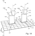
- Fig. 1A illustrates an imaging device 100 for wavelength dependent imaging.
- the imaging device 100 comprises a plurality of light propagating units 120a, 120b.
- the light propagating units 120a, 120b are of at least two different types, i.e. a first type and a second type, such that the plurality of light propagating units comprises at least a first light propagating unit 120a and a second light propagating unit 120b. It is conceivable that the imaging device 100 comprises more than one light propagating unit 120a, 120b of each type, however, in Fig. 1A only one light propagating unit 120a, 120b of each type is illustrated simplicity and brevity.
- Each respective light propagating unit 120a, 120b of the imaging device 100 comprises a funnel element 121 having a collecting end 122 and an opposite transmitting end 123.
- Each funnel element 121 defines a central funnel axis A1 extending from the collecting end 122 to the transmitting end 123.
- the collecting ends 122 of the plurality of light propagating units 120a,120b are arranged adjacent to each other leaving only small gaps, or no gaps, in between the different collecting ends 122.
- the collecting ends 122 are here illustrated to be arranged in perpendicular rows and columns such that the collecting ends 122 together form a planar surface. However, it is conceivable that the collecting ends 122 may be arranged in alternative manners.
- Each respective funnel element 121 is configured to collect light incident at the collecting end 122.
- the light may come from a scene being imaged by an objective lens (not shown here) onto the planar surface of collecting ends 122, however also other arrangements directing light onto the collecting ends 122 are conceivable.
- the funnel element 121 is further configured to propagate the light from the collecting end 122 to the transmitting end 123. As illustrated in Fig. 1A , the funnel element 121 is tapered such that the cross-section of the collecting end 122 is larger than the cross-section of the transmitting end 123.
- Each respective light propagating units 120a, 120b of the imaging device 100 comprises a waveguide 125 having a receiving end 126 and an opposite distributing end 127.
- Each waveguide 125 defines a central waveguide axis A2 extending from the receiving end 126 to the distributing end 127.
- the waveguide 125 is arranged such that the receiving end 126 is facing the transmitting end 123 of the funnel element 121.
- the waveguide 125 may be arranged such that the receiving end 126 is in direct contact with the transmitting end 123 of the funnel element 121.
- the waveguide 125 may be arranged such that a gap is formed between the receiving end 126 and the transmitting end 123.
- the waveguide 125 is configured to receive the light from the transmitting end 123 at the receiving end 126. Most of the light, and preferably all the light, collected at the collecting end 122 of the funnel element 121 may be propagated to the transmitting end 123 and coupled into the waveguide 125 via the receiving end 126.
- one or more additional layers may be provided between transmitting end 123 and the receiving end 126.
- the one or more additional layers may enhance the coupling of light between the funnel element 121 and the waveguide 125.
- the funnel element 121 and the waveguide 125 are asymmetrically coupled. More specifically the transmitting end 123 is coupled to the receiving end 126 such that the central funnel axis A1 at the transmitting end 123 is displaced with respect to the central waveguide axis A2 at the receiving end 126.
- the funnel element 121 and the waveguide 125 have a first asymmetric coupling such that the central funnel axis A1 at the transmitting end 123 has a first displacement with respect to the central waveguide axis A2 at the receiving end 126
- the funnel element 121 and the waveguide 125 have a second asymmetric coupling such that the central funnel axis A1 at the transmitting end 123 has a second displacement with respect to the central waveguide axis A2 at the receiving end 126.
- the second displacement is different from the first displacement, such that the first light propagating unit 120a and the second light propagating unit 120b have different asymmetric coupling.
- the waveguide 125 is further configured to propagate the light to the distributing end 127.
- the waveguide 125 is a multimode waveguide configured to propagate the light through the waveguide 125 in dependence of wavelength. By the present arrangement the spatial distribution of the light at the distributing end 127 is dependent on wavelength of the light. At the distributing end 127 the light may exit the waveguide 125.
- the imaging device 100 further comprises a detector 110 comprising a plurality of light sensitive elements 114 which here form an array 112 of light sensitive elements 114.
- the light sensitive elements 114 are arranged in a planar fashion in a detector plane. Although the light sensitive elements 114 are here illustrated to be arranged in perpendicular rows and columns of an array 112, it is conceivable that the light sensitive elements 114 may alternatively be arranged in other manners.
- Each respective light propagating unit 120a, 120b is arranged with respect to the detector 110 such that the distributing end 127 is facing the array 112 of light sensitive elements 114. More specifically, each light propagating unit 120a, 120b is arranged such that the distributing end 127 is facing at least two light sensitive elements 114. Thus, the light exiting the waveguide 126 at the distributing end 127 is incident onto the two light sensitive elements 114 of the array 112 of light sensitive elements 114.
- the collecting ends 122 of the funnel elements 121 are arranged in a common plane parallel to the detector plane.
- the central funnel axis A1 is arranged to be perpendicular to the detector plane.
- Each respective light sensitive element 114 is configured to generate an electric signal which is dependent on an intensity of the light incident onto the light sensitive element 114.
- the detector 110 may be an image detector such as charge-coupled devices (CCD) and complementary metal oxide semiconductors (CMOS). However, the detector 110 may alternatively be of another type.
- the two light sensitive elements 114 onto which the light at the distributing end 127 is incident may be considered to form a sub-set 118 of light sensitive elements 114.
- the plurality of light sensitive elements 114 may be divided into a plurality of sub-sets 118 of light sensitive elements 114.
- the sub-sets 118 comprise an equal number of light sensitive elements 114, in the present example two light sensitive element 114.
- the light sensitive elements 114 correspond to the light sensitive elements covered by the respective distributing end 127 of the light propagating unit 120a, 120b.
- the distribution of the light at the distributing end 127 is dependent on wavelength of the received light.
- the wavelengths of the light may be distributed by increasing wavelength from one edge of the distributing end 127 to an opposite edge of the distributing end 127, across the light sensitive elements 114 of the sub-set 118.
- other types of distributions based on wavelength are conceivable.
- sub-sets 118 are here illustrated to comprise only two light sensitive elements 114, the sub-sets 118 may alternatively comprise more light sensitive elements 114, such as three, four, five, six, or more light sensitive elements. Further, it should be understood that, although the sub-set 118 is here illustrated as comprising light sensitive elements 114 arranged along a single row, such as 1x2 light sensitive elements 114, the sub-sets 118 may alternatively comprise light sensitive elements 114 arranged in more than one row, such as 2x2, 2x3, 3x3, 3x4, 4x4, or more light sensitive elements 114.
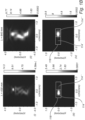
- Fig. 1B illustrates an example of how blue light (left column) and red light (right column) may be distributed in the waveguide, respectively.
- Light with a wavelength of 430 nm here represents blue light
- light with a wavelength of 640 nm here represents red light.
- the present description is by no means limited to these wavelengths. Rather light may be of any wavelengths within the visible, UV and IR part of the electromagnetic spectrum.
- the top row illustrates a side view of the waveguide and how light at the respective wavelengths is distributed, as it propagates from the receiving end (upper part) to the distributing end (lower part).
- the bottom row illustrates how light at the respective wavelengths is distributed at the distributing end, wherein the white rectangles represent the light sensitive elements 114', 114" onto which light from the distributing end is incident.
- the white rectangles represent the light sensitive elements 114', 114" onto which light from the distributing end is incident.
- a major portion of the blue (430 nm) light is incident onto light sensitive element 114', whereas a major portion of the red (640 nm) light is incident onto light sensitive element 114".
- the sub-set 118 of light sensitive elements 114', 114" of the imaging device 100 may be able to distinguish between blue and red light incident onto the light propagating unit.
- the waveguide is configured to propagate the light through the waveguide in dependence of wavelength such that the light at the distributing end is distributed into two wavelength bands linearly distributed along the distributing end.
- Each of the two wavelength bands is associated with a mutually unique light sensitive element 114', 114" of the two light sensitive elements.
- the wavelength bands are ordered along the distributing end in a descending manner with respect to wavelength, from right to left in Fig. 1B .
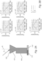
- Fig. 2A and 2B illustrate the effect of such a dependance.
- Fig. 2A illustrates light with an angle of incidence ⁇ with respect to the normal N of the collecting end 122 of the funnel element 121.
- the light propagating unit is a first light propagating unit 120a.
- Fig. 2B illustrates transmission of light as a function of wavelength of the light received at the two light sensitive elements 114', 114", at a number of different angles of incidence.
- the curve denoted T L represents the light received at light sensitive element 114'
- the curve denoted T R represents the light received at light sensitive element 114".
- the major portion of the light received at light sensitive element 114' has a wavelength below 500 nm with a peak at about 450 nm.
- a wavelength band may be considered to represent blue light.
- the major portion of the light received at light sensitive element 114" has a wavelength above 500 nm with a peak at about 600 nm.
- such a wavelength band may be considered to represent red light.
- the two light sensitive elements 114', 114" may be able to distinguish between the two wavelength bands, i.e. blue and red in the present example.
- a light propagating unit having an asymmetric coupling configured for efficient propagation and distribution of light collected at normal incidence may not necessarily be optimal for efficient propagation and distribution of light collected at oblique angles. Rather, for oblique angles a different asymmetric coupling may provide a more efficient propagation and distribution of light. This will be discussed in relation to the following figures.
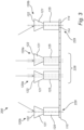
- Fig. 3 illustrates an imaging device 200 for wavelength dependent imaging.
- the imaging device 200 comprises a plurality of light propagating units 120a, 120b arranged across a detector 110 comprising a plurality of light sensitive elements 114.
- the light propagating units 120a, 120b are of at least two different types, i.e. a first type and a second type, such that the plurality of light propagating units comprises at least a first light propagating unit 120a and a second light propagating unit 120b.
- Imaging device 200 shares some of the features with imaging device 100 described in relation to Fig. 1A-1B , the details of which are not repeated here.
- light incident onto a central portion of the detector 110 when projecting an image of a scene onto the imaging device 200, light incident onto a central portion of the detector 110 is expected to have normal or close to normal incidence.
- light incident onto a peripheral portion of the detector 110 is expected to have an oblique angle of incidence.
- light incident onto a peripheral portion of the detector 110 may be expected to have an angle of incidence larger than ⁇ 10°.
- the plurality of light propagating units 120a, 120b is arranged in a central zone 228 arranged at a central portion of the detector 110, and a peripheral zone 229 arranged at a peripheral portion of the detector 100.
- the funnel element 121 and the waveguide 125 have the first asymmetric coupling.
- the funnel element 121 and the waveguide 125 have the second asymmetric coupling.
- the first displacement is larger than the second displacement.
- the light propagating units 120a having the first asymmetric coupling are configured for efficient propagation and distribution of light collected at normal incidence to the collecting end 122.
- the light propagating units 120b having the second asymmetric coupling with a second displacement, smaller than the first displacement, between the funnel element 121 and the waveguide 125, are configured for efficient propagation and distribution of light collected at oblique angles of incidence to the collecting end 122.
- the imaging device 200 may be configured to receive light incident with a different angle of incidence onto different light propagating units 120a, 120b of the plurality of light propagating units 120a, 120b, depending on their location on the detector 110. Since the different light propagating units 120a, 120b are arranged with different asymmetric coupling of the funnel element 121 to the waveguide 125 depending on their location on the detector 110, propagation of the light in the waveguides 125 may be compensated for the angle of incidence. In the manner described above, an imaging device 200 for wavelength dependent imaging with a more uniform sensitivity and light distributing performance across the detector 110 may be provided.
- a gap is illustrated between the central zone 228 and the peripheral zone 229.
- this region is provided with light propagating units.
- the central zone 228 and or the peripheral zone are expanded such that the gap is eliminated.
- the gap may comprise light propagating units 120a having the first asymmetric coupling, or the gap may comprise light propagating units 120b having the second asymmetric coupling, or the gap may comprise a combination thereof.
- the gap may represent an intermediate zone comprising light propagating units having an asymmetric coupling different from the first and second asymmetric couplings, as will be discussed in relation to the following figure.
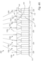
- Fig. 4A illustrates an imaging device 300 for wavelength dependent imaging.
- the imaging device 300 comprises a plurality of light propagating units 120a, 120b, 120c arranged across a detector 110 comprising a plurality of light sensitive elements 114.
- the light propagating units 120a of a central zone 328 are of the first type, and the light propagating units 120b of a peripheral zone 329 are of the second type.
- Imaging device 300 shares some of the features with imaging device 100 described in relation to Fig. 1A-1B , and with imaging device 200 described in relation to Fig. 3 , the details of which are not repeated here.
- the plurality of light propagating units 120a, 120b, 120c is further arranged in an intermediate zone 324.
- the intermediate zone 324 is arranged between the central zone 328 and the peripheral zone 329.
- a size of a displacement of the central funnel axis A1 at the transmitting end 123 with respect to the central waveguide axis A2 at the receiving end 126 gradually transitions from the first displacement towards the second displacement with decreasing size of the displacement from the central zone 328, through the intermediate zone 324 towards the peripheral zone 329.
- the imaging device 300 may be configured to receive light with normal incidence at the central portion of the detector 110 and with increasing angle incidence with increasing distance from the central portion.
- the different light propagating units 120a, 120b, 120c are arranged with gradually transitioning asymmetric coupling from the central portion towards the peripheral portion so as to compensate the propagation of the light in the waveguides 125 for the difference in angle of incidence across the detector 110.
- an imaging device 300 for wavelength dependent imaging with an even more uniform sensitivity and light distributing performance across the detector 110 may be provided.
- the plurality of light propagating units 120a, 120b, 120c is arranged to present a symmetry axis S.
- the asymmetric coupling of the light propagating units 120a, 120b, 120c on a first side of the symmetry axis S is mirrored with respect to the asymmetric coupling of the light propagating units 120a, 120b, 120c on an opposite second side of the symmetry axis S.
- light is expected to have normal incidence at the central portion of the detector, and to have an increasing angle of incidence with increasing distance from the central portion of the detector.
- the angle of incidence may have opposite direction at the first and second sides of the symmetry axis S.
- the angle of incidence may be mirrored with respect to the symmetry axis S.
- the light propagating units 120a, 120b, 120c may also be mirrored.
- mirroring the light propagating units 120a, 120b, 120c with respect to the symmetry axis S may also mirror the order of the wavelength bands detected by the respective light sensitive elements 114.
- the light propagating units 120a, 120b, 120c on the first side of the symmetry axis S distribute the wavelength bands in descending order in a given direction
- the light propagating units 120a, 120b, 120c on the second side of the symmetry axis S may distribute the wavelength bands in ascending order in the same direction.
- an imaging device may have more than one symmetry axis, such as two symmetry axes.
- a symmetry axis may be arranged to extend in parallel with a side of the detector 110.
- a symmetry axis may be arranged to extend along a diagonal of the detector 110, i.e. extending from a corner of the detector 110 to an opposite corner of the detector 110.
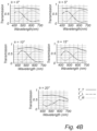
- Fig. 4B illustrates transmission of light as a function of wavelength of the light received at the respective light sensitive elements 114', 114" of the imaging device 300, at a number of different light propagating units 120a, 120b, 120c across the detector 110 receiving a number of different angles of incidence.
- the curve denoted T L represents the light received at a light sensitive element 114'
- the curve denoted T R represents the light received at a light sensitive element 114".
- the major portion of the light received at light sensitive element 114' has a wavelength below 500 nm with a peak at about 450 nm (blue). Further, for normal incidence, the major portion of the light received at light sensitive element 114" has a wavelength above 500 nm with a peak at about 600 nm (red).
- a minor shift of the respective curves may be seen in Fig. 4B as well, but the light transmission and distribution may still be efficient.
- the imaging device 300 may in the manner described above provide compensation of propagation of light in the waveguides for angle of incidence of the light.
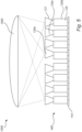
- Fig. 5 schematically illustrates an imaging system 1000 for wavelength dependent imaging.
- the imaging system 1000 comprises an imaging device 400.
- the imaging device 400 may be any one of the imaging devices 100, 200, 300 as previously described.
- the imaging system 1000 further comprises an objective lens 1500.
- the objective lens 1500 is configured to project an image of a scene (not illustrated here) onto the plurality of light propagating units 120a, 120b, 120c of the imaging device 400.
- Dependent on the objective lens 1500 light from the scene may be incident with a different angle of incidence onto different light propagating units 120a, 120b, 120c, depending on the location on the detector 110 of the different light propagating units120a, 120b, 120c.
- the angle of incidence at different locations of the detector 110 may be known.
- the imaging device 400 may be tailored to fit the objective lens 1500, such that the different light propagating units 120a, 120b, 120c are arranged with different asymmetric coupling of the funnel element 121 to the waveguide 125 depending on the location on the detector 110 of the different light propagating units 120a, 120b, 120c, so as to compensate propagation of the light in each waveguide 125 for the angle of incidence at the different locations across the detector 110.
- an imaging system with substantially the same wavelength dependence for propagation of the light through all light propagating units 120a, 120b, 120c may be provided.
- any of the imaging devices 100, 200, 300, 400 illustrated above may optionally be further configured to propagate the light through the waveguide 125 in dependence of polarization such that a spatial distribution of the light at the distributing end is dependent on polarization of the light, in addition to being dependence on wavelength.
- the light propagating units may distribute light in dependence of wavelength in one direction and may further distribute light in dependence of polarization in another, perpendicular direction.
- the distributing end may distribute light towards a sub-set of 2x2, 3x3, 4x4, or 5x5 or more light sensitive elements 114. In the manner presently described one spatial direction on the detector 110 may represent wavelength whereas another perpendicular direction may represent polarization of the incident light.
- Fig. 6 illustrates a schematic block diagram shortly summarizing the method for wavelength dependent imaging. It should be understood that the steps of the method, although listed in a specific order herein, may be performed in any order suitable.
- the method may comprise collecting S602, by a plurality of light propagating units, light incident at a collecting end of a respective funnel element of each light propagating unit of the plurality of light propagating units.
- the method may comprise propagating S604, for each light propagation unit, the light to a transmitting end of the funnel element, wherein a cross-section of the collecting end is larger than a cross-section of the transmitting end, and wherein the funnel element defines a central funnel axis extending from the collecting end to the transmitting end.
- the method may comprise receiving S606, at a receiving end of a waveguide of each light propagating unit, the light from the transmitting end.
- the method may comprise propagating S608, for each light propagation unit, the light to a distributing end of the waveguide, wherein the waveguide is a multimode waveguide, and wherein the propagating the light through the waveguide is dependent on wavelength such that a spatial distribution of the light at the distributing end is dependent on wavelength of the light, and wherein the waveguide defines a central waveguide axis extending from the receiving end to the distributing end.
- the propagating the light to a distributing end may further comprise distributing the light into at least two wavelength bands linearly distributed along the distributing end, wherein each of the at least two wavelength bands is associated with a mutually unique light sensitive element of the at least two light sensitive elements.
- the funnel element and the waveguide have a first asymmetric coupling such that the central funnel axis at the transmitting end has a first displacement with respect to the central waveguide axis at the receiving end
- the funnel element and the waveguide have a second asymmetric coupling such that the central funnel axis at the transmitting end has a second displacement with respect to the central waveguide axis at the receiving end, wherein the second displacement is different from the first displacement
- the method may comprise detecting S610, for each light propagating unit, the light at the distributing end, by at least two light sensitive elements of a plurality of light sensitive elements, such that each light sensitive element generates an electric signal dependent on an intensity of light incident onto the light sensitive element.
- the plurality of light propagating units may comprise at least a central zone arranged at a central portion of the detector, and a peripheral zone arranged at a peripheral portion of the detector.
- the funnel element and the waveguide are asymmetrically coupled.
Landscapes
- Physics & Mathematics (AREA)
- General Physics & Mathematics (AREA)
- Spectroscopy & Molecular Physics (AREA)
- Optics & Photonics (AREA)
- Engineering & Computer Science (AREA)
- Multimedia (AREA)
- Signal Processing (AREA)
- Solid State Image Pick-Up Elements (AREA)
- Photometry And Measurement Of Optical Pulse Characteristics (AREA)
Claims (13)
- Dispositif d'imagerie pour une imagerie dépendante de la longueur d'onde, comprenant :un détecteur comprenant une pluralité d'éléments photosensibles, dans lequel chaque élément photosensible est configuré pour générer un signal électrique dépendant de l'intensité de la lumière incidente sur l'élément photosensible ;une pluralité d'unités de propagation de la lumière, dans lequel chaque unité de propagation de la lumière de la pluralité d'unités de propagation de lumière comprend :un élément de tunnel doté d'une extrémité de collecte et d'une extrémité d'émission et définissant un axe central de tunnel s'étendant de l'extrémité de collecte à l'extrémité d'émission, l'élément de tunnel étant configuré pour collecter la lumière incidente à l'extrémité de collecte et propager la lumière vers l'extrémité d'émission, dans lequel la section transversale de l'extrémité de collecte est supérieure à celle de l'extrémité d'émission ;un guide d'ondes doté d'une extrémité de réception et une extrémité de distribution et définissant un axe de guide d'ondes central s'étendant de l'extrémité de réception à l'extrémité de distribution, le guide d'ondes étant configuré pour recevoir la lumière de l'extrémité d'émission à l'extrémité de réception et pour propager la lumière vers l'extrémité de distribution, dans lequel le guide d'ondes est un guide d'ondes multimode configuré pour propager la lumière à travers le guide d'ondes en fonction de la longueur d'onde, de sorte qu'une distribution spatiale de la lumière à l'extrémité de distribution dépende de la longueur d'onde de la lumière ;dans lequel, pour une première unité de propagation de la lumière, l'élément de tunnel et le guide d'ondes présentent un premier couplage asymétrique de sorte que l'axe central de tunnel à l'extrémité d'émission présente un premier déplacement par rapport à l'axe central de guide d'ondes à l'extrémité de réception et pour une deuxième unité de propagation de la lumière, l'élément de tunnel et le guide d'ondes présentent un deuxième couplage asymétrique de sorte que l'axe central de tunnel à l'extrémité d'émission présente un deuxième déplacement par rapport à l'axe central de guide d'ondes à l'extrémité de réception, dans lequel le deuxième déplacement est différent du premier déplacement ;dans lequel, pour chaque unité de propagation de lumière, l'unité de propagation de lumière est disposée par rapport au détecteur de telle sorte que la lumière à l'extrémité de distribution soit incidente sur au moins deux éléments photosensibles parmi la pluralité d'éléments photosensibles.
- Dispositif d'imagerie selon la revendication 1, dans lequel, pour chaque unité de propagation de lumière, le guide d'ondes est configuré pour propager la lumière à travers le guide d'ondes en fonction de la longueur d'onde, de sorte que la lumière à l'extrémité de distribution soit distribuée en au moins deux bandes de longueurs d'onde réparties linéairement le long de l'extrémité de distribution et dans lequel chacune de ces deux bandes de longueurs d'onde est associée à un élément photosensible mutuellement unique des au moins deux éléments photosensibles.
- Dispositif d'imagerie selon la revendication 2, dans lequel, pour chaque unité de propagation de lumière, les bandes de longueurs d'onde sont ordonnées le long de l'extrémité de distribution de manière décroissante par rapport à la longueur d'onde.
- Dispositif d'imagerie selon une quelconque des revendications précédentes, dans lequel la pluralité d'éléments photosensibles est disposée de manière plane dans un plan de détection,dans lequel les extrémités de collecte des éléments de tunnel de toutes les unités de propagation de lumière de la pluralité d'unités de propagation de lumière sont disposées dans un plan commun parallèle au plan de détection, etdans lequel, pour chaque unité de propagation de lumière, l'axe central de tunnel est perpendiculaire au plan de détection.
- Dispositif d'imagerie selon une quelconque des revendications précédentes, dans lequel la pluralité d'unités de propagation de lumière est disposée dans au moins une zone centrale disposée au centre du détecteur et une zone périphérique disposée au bord du détecteur,
dans lequel, pour les unités de propagation de lumière disposées dans la zone centrale, l'élément de tunnel et le guide d'ondes présentent le premier couplage asymétrique, et pour les unités de propagation de lumière disposées dans la zone périphérique, l'élément de tunnel et le guide d'ondes présentent le deuxième couplage asymétrique. - Dispositif d'imagerie selon la revendication 5, dans lequel le premier déplacement est supérieur au deuxième déplacement.
- Dispositif d'imagerie selon une quelconque des revendications 5 ou 6, dans lequel la pluralité d'unités de propagation de lumière est en outre disposée dans une ou plusieurs zones intermédiaires situées entre la zone centrale et la zone périphérique ; et
dans lequel, pour les unités de propagation de lumière disposées dans la zone centrale, la ou les zones intermédiaires et la zone périphérique, une ampleur d'un déplacement de l'axe central de tunnel à l'extrémité d'émission par rapport à l'axe central de guide d'ondes à l'extrémité de réception passe progressivement du premier déplacement pour les unités de propagation de lumière disposées dans la zone centrale au deuxième déplacement pour les unités de propagation de lumière disposées dans la zone périphérique, l'ampleur du déplacement décroissant de la zone centrale à travers la ou les zones intermédiaires vers la zone périphérique. - Dispositif d'imagerie selon une quelconque des revendications précédentes, dans lequel la pluralité d'unités de propagation de lumière est agencée pour présenter un axe de symétrie tel qu'un couplage asymétrique des unités de propagation de lumière d'un premier côté de l'axe de symétrie soit configuré pour être réfléchi par rapport à un couplage asymétrique des unités de propagation de lumière d'un deuxième côté de l'axe de symétrie, le deuxième côté étant opposé au premier par rapport à l'axe de symétrie.
- Dispositif d'imagerie selon une quelconque des revendications précédentes, dans lequel, pour chaque unité de propagation de lumière, le guide d'ondes est en outre configuré pour propager la lumière à travers le guide d'ondes en fonction de la polarisation, de sorte qu'une distribution spatiale de la lumière à l'extrémité de distribution dépende de la longueur d'onde et de la polarisation de la lumière.
- Système d'imagerie comprenant :un dispositif d'imagerie selon une quelconque des revendications précédentes ;un objectif configuré pour projeter une image d'une scène sur la pluralité d'unités de propagation de lumière du dispositif d'imagerie, dans lequel la lumière de la scène est incidente avec un angle d'incidence différent sur les différentes unités de propagation de lumière de la pluralité d'unités de propagation de lumière, en fonction d'un emplacement sur le détecteur des différentes unités de propagation de lumière par rapport à l'objectif ;dans lequel les différentes unités de propagation de lumière sont disposées avec un couplage asymétrique différent de l'élément de tunnel au guide d'ondes, en fonction de l'emplacement sur le détecteur, de manière à compenser la propagation de la lumière dans chaque guide d'ondes en fonction de l'angle d'incidence.
- Procédé d'imagerie dépendant de la longueur d'onde, comprenant :la collecte, par une pluralité d'unités de propagation de lumière, de la lumière incidente à une extrémité de collecte d'un élément de tunnel respectif de chaque unité de propagation de lumière de la pluralité d'unités de propagation de lumière ;la propagation, pour chaque unité de propagation lumineuse, de la lumière jusqu'à une extrémité de transmission de l'élément de tunnel, dans lequel une section transversale de l'extrémité de collecte est plus grande qu'une section transversale de l'extrémité d'émission et dans lequel l'élément de tunnel définit un axe central s'étendant de l'extrémité de collecte à l'extrémité d'émission ;la réception, à une extrémité de réception d'un guide d'ondes de chaque unité de propagation lumineuse, de la lumière provenant de l'extrémité d'émission ;la propagation, pour chaque unité de propagation lumineuse, de la lumière jusqu'à une extrémité de distribution du guide d'ondes, dans lequel le guide d'ondes est un guide d'ondes multimode et dans lequel la propagation de la lumière à travers le guide d'ondes dépend de la longueur d'onde, de sorte qu'une distribution spatiale de la lumière à l'extrémité de distribution dépende de la longueur d'onde de la lumière, et dans lequel le guide d'ondes définit un axe central de guide d'onde s'étendant de l'extrémité de réception à l'extrémité de distribution ;dans lequel, pour une première unité de propagation de lumière, l'élément de tunnel et le guide d'ondes présentent un premier couplage asymétrique tel que l'axe central de tunnel à l'extrémité d'émission présente un premier décalage par rapport à l'axe central de guide d'ondes à l'extrémité de réception et pour une deuxième unité de propagation de lumière, l'élément de tunnel et le guide d'ondes présentent un deuxième couplage asymétrique de sorte que l'axe central de tunnel à l'extrémité d'émission présente un deuxième décalage par rapport à l'axe central de guide d'ondes à l'extrémité de réception, dans lequel le deuxième déplacement est différent du premier déplacement etla détection, pour chaque unité de propagation de lumière, de la lumière à l'extrémité de distribution par au moins deux éléments photosensibles parmi une pluralité d'éléments photosensibles, de sorte que chaque élément photosensible génère un signal électrique dépendant d'une intensité lumineuse incidente sur l'élément photosensible.
- Procédé selon la revendication 11, dans lequel la propagation de la lumière vers une extrémité de distribution comprend en outre la distribution de la lumière dans au moins deux bandes de longueurs d'onde réparties linéairement le long de l'extrémité de distribution, dans lequel chacune des deux bandes de longueurs d'onde est associée à un élément photosensible mutuellement unique des au moins deux éléments photosensibles.
- Procédé selon une quelconque des revendications 11 ou 12, dans lequel la pluralité d'unités de propagation de la lumière comprend au moins une zone centrale disposée au centre du détecteur et une zone périphérique disposée au bord du détecteur,
dans lequel, pour les unités de propagation de lumière de la zone centrale, l'élément de tunnel et le guide d'ondes sont couplés de manière asymétrique.
Priority Applications (2)
| Application Number | Priority Date | Filing Date | Title |
|---|---|---|---|
| EP22215329.8A EP4390340B1 (fr) | 2022-12-21 | 2022-12-21 | Dispositif d'imagerie, système d'imagerie et procédé d'imagerie dépendant de la longueur d'onde |
| US18/392,354 US12429660B2 (en) | 2022-12-21 | 2023-12-21 | Imaging device, an imaging system and a method for wavelength dependent imaging |
Applications Claiming Priority (1)
| Application Number | Priority Date | Filing Date | Title |
|---|---|---|---|
| EP22215329.8A EP4390340B1 (fr) | 2022-12-21 | 2022-12-21 | Dispositif d'imagerie, système d'imagerie et procédé d'imagerie dépendant de la longueur d'onde |
Publications (2)
| Publication Number | Publication Date |
|---|---|
| EP4390340A1 EP4390340A1 (fr) | 2024-06-26 |
| EP4390340B1 true EP4390340B1 (fr) | 2025-06-11 |
Family
ID=84547393
Family Applications (1)
| Application Number | Title | Priority Date | Filing Date |
|---|---|---|---|
| EP22215329.8A Active EP4390340B1 (fr) | 2022-12-21 | 2022-12-21 | Dispositif d'imagerie, système d'imagerie et procédé d'imagerie dépendant de la longueur d'onde |
Country Status (2)
| Country | Link |
|---|---|
| US (1) | US12429660B2 (fr) |
| EP (1) | EP4390340B1 (fr) |
Families Citing this family (2)
| Publication number | Priority date | Publication date | Assignee | Title |
|---|---|---|---|---|
| EP4286806B1 (fr) * | 2022-06-01 | 2025-01-08 | Imec VZW | Dispositif et procédé d'imagerie dépendant de la polarisation |
| EP4678975A1 (fr) * | 2024-07-09 | 2026-01-14 | Imec VZW | Dispositif électroluminescent, affichage et procédé d'émission de lumière |
Family Cites Families (5)
| Publication number | Priority date | Publication date | Assignee | Title |
|---|---|---|---|---|
| US8384818B2 (en) * | 2008-06-18 | 2013-02-26 | Panasonic Corporation | Solid-state imaging device including arrays of optical elements and photosensitive cells |
| JP5506517B2 (ja) * | 2010-04-12 | 2014-05-28 | キヤノン株式会社 | 固体撮像素子 |
| JP5812610B2 (ja) * | 2011-01-18 | 2015-11-17 | キヤノン株式会社 | 固体撮像素子及び固体撮像素子を有する撮像システム |
| EP3770660B1 (fr) * | 2019-07-24 | 2025-03-12 | Imec VZW | Détecteur comprenant un guide d'ondes |
| EP3944323B1 (fr) * | 2020-07-21 | 2024-06-05 | Imec VZW | Détecteur servant à détecter un rayonnement électromagnétique, capteur d'images et procédé de détection d'informations d'image |
-
2022
- 2022-12-21 EP EP22215329.8A patent/EP4390340B1/fr active Active
-
2023
- 2023-12-21 US US18/392,354 patent/US12429660B2/en active Active
Also Published As
| Publication number | Publication date |
|---|---|
| US20240210641A1 (en) | 2024-06-27 |
| US12429660B2 (en) | 2025-09-30 |
| EP4390340A1 (fr) | 2024-06-26 |
Similar Documents
| Publication | Publication Date | Title |
|---|---|---|
| KR102316447B1 (ko) | 광 이용 효율이 향상된 이미지 센서 | |
| US12429660B2 (en) | Imaging device, an imaging system and a method for wavelength dependent imaging | |
| US10393576B2 (en) | Image sensor including color filter isolation layer and method of manufacturing the same | |
| US10840293B2 (en) | Image sensor structure | |
| US9653501B2 (en) | Image sensor including color filter and method of manufacturing the image sensor | |
| EP3770660B1 (fr) | Détecteur comprenant un guide d'ondes | |
| US9496300B2 (en) | Imaging device having array of spectroscopic sections wherein an interval between two spectroscopic sections at a periphery of an imaging plane is smaller than an interval between two spectroscopic sections at a center of the imaging plane | |
| US20130181113A1 (en) | Solid-state imaging equipment | |
| EP3450938B1 (fr) | Capteur d'image et appareil d'imagerie | |
| JP7704856B2 (ja) | 拡大されたスペクトル領域を有するマルチスペクトルイメージャ | |
| US9316839B2 (en) | Image sensor having improved light utilization efficiency | |
| EP4037299A1 (fr) | Élément de capture d'image et dispositif de capture d'image | |
| JP2005167356A (ja) | 撮像素子 | |
| EP4390484A1 (fr) | Dispositif et procédé d'imagerie dépendant de la polarisation | |
| US12480814B2 (en) | Device and a method for polarization dependent imaging | |
| US11758294B2 (en) | Imaging system and method for acquisition of multi-spectral images | |
| EP4498049A1 (fr) | Dispositif intégré, système d'imagerie et procédé de détection de lumière en fonction de la longueur d'onde | |
| EP4668338A1 (fr) | Dispositif d'imagerie et procédé d'imagerie dépendant de la longueur d'onde |
Legal Events
| Date | Code | Title | Description |
|---|---|---|---|
| PUAI | Public reference made under article 153(3) epc to a published international application that has entered the european phase |
Free format text: ORIGINAL CODE: 0009012 |
|
| STAA | Information on the status of an ep patent application or granted ep patent |
Free format text: STATUS: THE APPLICATION HAS BEEN PUBLISHED |
|
| AK | Designated contracting states |
Kind code of ref document: A1 Designated state(s): AL AT BE BG CH CY CZ DE DK EE ES FI FR GB GR HR HU IE IS IT LI LT LU LV MC ME MK MT NL NO PL PT RO RS SE SI SK SM TR |
|
| STAA | Information on the status of an ep patent application or granted ep patent |
Free format text: STATUS: REQUEST FOR EXAMINATION WAS MADE |
|
| 17P | Request for examination filed |
Effective date: 20241129 |
|
| RBV | Designated contracting states (corrected) |
Designated state(s): AL AT BE BG CH CY CZ DE DK EE ES FI FR GB GR HR HU IE IS IT LI LT LU LV MC ME MK MT NL NO PL PT RO RS SE SI SK SM TR |
|
| GRAP | Despatch of communication of intention to grant a patent |
Free format text: ORIGINAL CODE: EPIDOSNIGR1 |
|
| STAA | Information on the status of an ep patent application or granted ep patent |
Free format text: STATUS: GRANT OF PATENT IS INTENDED |
|
| RIC1 | Information provided on ipc code assigned before grant |
Ipc: G01J 3/02 20060101AFI20250306BHEP |
|
| INTG | Intention to grant announced |
Effective date: 20250324 |
|
| GRAS | Grant fee paid |
Free format text: ORIGINAL CODE: EPIDOSNIGR3 |
|
| GRAA | (expected) grant |
Free format text: ORIGINAL CODE: 0009210 |
|
| STAA | Information on the status of an ep patent application or granted ep patent |
Free format text: STATUS: THE PATENT HAS BEEN GRANTED |
|
| AK | Designated contracting states |
Kind code of ref document: B1 Designated state(s): AL AT BE BG CH CY CZ DE DK EE ES FI FR GB GR HR HU IE IS IT LI LT LU LV MC ME MK MT NL NO PL PT RO RS SE SI SK SM TR |
|
| REG | Reference to a national code |
Ref country code: GB Ref legal event code: FG4D |
|
| REG | Reference to a national code |
Ref country code: CH Ref legal event code: EP |
|
| REG | Reference to a national code |
Ref country code: IE Ref legal event code: FG4D |
|
| REG | Reference to a national code |
Ref country code: DE Ref legal event code: R096 Ref document number: 602022015778 Country of ref document: DE |
|
| P01 | Opt-out of the competence of the unified patent court (upc) registered |
Free format text: CASE NUMBER: APP_32303/2025 Effective date: 20250703 |
|
| REG | Reference to a national code |
Ref country code: NL Ref legal event code: FP |
|
| PG25 | Lapsed in a contracting state [announced via postgrant information from national office to epo] |
Ref country code: ES Free format text: LAPSE BECAUSE OF FAILURE TO SUBMIT A TRANSLATION OF THE DESCRIPTION OR TO PAY THE FEE WITHIN THE PRESCRIBED TIME-LIMIT Effective date: 20250611 Ref country code: FI Free format text: LAPSE BECAUSE OF FAILURE TO SUBMIT A TRANSLATION OF THE DESCRIPTION OR TO PAY THE FEE WITHIN THE PRESCRIBED TIME-LIMIT Effective date: 20250611 |
|
| REG | Reference to a national code |
Ref country code: LT Ref legal event code: MG9D |
|
| PG25 | Lapsed in a contracting state [announced via postgrant information from national office to epo] |
Ref country code: GR Free format text: LAPSE BECAUSE OF FAILURE TO SUBMIT A TRANSLATION OF THE DESCRIPTION OR TO PAY THE FEE WITHIN THE PRESCRIBED TIME-LIMIT Effective date: 20250912 Ref country code: NO Free format text: LAPSE BECAUSE OF FAILURE TO SUBMIT A TRANSLATION OF THE DESCRIPTION OR TO PAY THE FEE WITHIN THE PRESCRIBED TIME-LIMIT Effective date: 20250911 |
|
| PG25 | Lapsed in a contracting state [announced via postgrant information from national office to epo] |
Ref country code: BG Free format text: LAPSE BECAUSE OF FAILURE TO SUBMIT A TRANSLATION OF THE DESCRIPTION OR TO PAY THE FEE WITHIN THE PRESCRIBED TIME-LIMIT Effective date: 20250611 |
|
| PG25 | Lapsed in a contracting state [announced via postgrant information from national office to epo] |
Ref country code: HR Free format text: LAPSE BECAUSE OF FAILURE TO SUBMIT A TRANSLATION OF THE DESCRIPTION OR TO PAY THE FEE WITHIN THE PRESCRIBED TIME-LIMIT Effective date: 20250611 |
|
| PG25 | Lapsed in a contracting state [announced via postgrant information from national office to epo] |
Ref country code: RS Free format text: LAPSE BECAUSE OF FAILURE TO SUBMIT A TRANSLATION OF THE DESCRIPTION OR TO PAY THE FEE WITHIN THE PRESCRIBED TIME-LIMIT Effective date: 20250911 |
|
| PG25 | Lapsed in a contracting state [announced via postgrant information from national office to epo] |
Ref country code: LV Free format text: LAPSE BECAUSE OF FAILURE TO SUBMIT A TRANSLATION OF THE DESCRIPTION OR TO PAY THE FEE WITHIN THE PRESCRIBED TIME-LIMIT Effective date: 20250611 |
|
| PG25 | Lapsed in a contracting state [announced via postgrant information from national office to epo] |
Ref country code: PT Free format text: LAPSE BECAUSE OF FAILURE TO SUBMIT A TRANSLATION OF THE DESCRIPTION OR TO PAY THE FEE WITHIN THE PRESCRIBED TIME-LIMIT Effective date: 20251013 |
|
| PGFP | Annual fee paid to national office [announced via postgrant information from national office to epo] |
Ref country code: NL Payment date: 20251119 Year of fee payment: 4 |
|
| REG | Reference to a national code |
Ref country code: AT Ref legal event code: MK05 Ref document number: 1802601 Country of ref document: AT Kind code of ref document: T Effective date: 20250611 |
|
| PG25 | Lapsed in a contracting state [announced via postgrant information from national office to epo] |
Ref country code: IS Free format text: LAPSE BECAUSE OF FAILURE TO SUBMIT A TRANSLATION OF THE DESCRIPTION OR TO PAY THE FEE WITHIN THE PRESCRIBED TIME-LIMIT Effective date: 20251011 |
|
| PGFP | Annual fee paid to national office [announced via postgrant information from national office to epo] |
Ref country code: DE Payment date: 20251126 Year of fee payment: 4 |
|
| PG25 | Lapsed in a contracting state [announced via postgrant information from national office to epo] |
Ref country code: AT Free format text: LAPSE BECAUSE OF FAILURE TO SUBMIT A TRANSLATION OF THE DESCRIPTION OR TO PAY THE FEE WITHIN THE PRESCRIBED TIME-LIMIT Effective date: 20250611 Ref country code: SM Free format text: LAPSE BECAUSE OF FAILURE TO SUBMIT A TRANSLATION OF THE DESCRIPTION OR TO PAY THE FEE WITHIN THE PRESCRIBED TIME-LIMIT Effective date: 20250611 |
|
| PGFP | Annual fee paid to national office [announced via postgrant information from national office to epo] |
Ref country code: FR Payment date: 20251120 Year of fee payment: 4 |
|
| PGFP | Annual fee paid to national office [announced via postgrant information from national office to epo] |
Ref country code: BE Payment date: 20251119 Year of fee payment: 4 |
|
| PG25 | Lapsed in a contracting state [announced via postgrant information from national office to epo] |
Ref country code: CZ Free format text: LAPSE BECAUSE OF FAILURE TO SUBMIT A TRANSLATION OF THE DESCRIPTION OR TO PAY THE FEE WITHIN THE PRESCRIBED TIME-LIMIT Effective date: 20250611 |
|
| PG25 | Lapsed in a contracting state [announced via postgrant information from national office to epo] |
Ref country code: PL Free format text: LAPSE BECAUSE OF FAILURE TO SUBMIT A TRANSLATION OF THE DESCRIPTION OR TO PAY THE FEE WITHIN THE PRESCRIBED TIME-LIMIT Effective date: 20250611 |
|
| PG25 | Lapsed in a contracting state [announced via postgrant information from national office to epo] |
Ref country code: EE Free format text: LAPSE BECAUSE OF FAILURE TO SUBMIT A TRANSLATION OF THE DESCRIPTION OR TO PAY THE FEE WITHIN THE PRESCRIBED TIME-LIMIT Effective date: 20250611 |
|
| PG25 | Lapsed in a contracting state [announced via postgrant information from national office to epo] |
Ref country code: SK Free format text: LAPSE BECAUSE OF FAILURE TO SUBMIT A TRANSLATION OF THE DESCRIPTION OR TO PAY THE FEE WITHIN THE PRESCRIBED TIME-LIMIT Effective date: 20250611 |
|
| PG25 | Lapsed in a contracting state [announced via postgrant information from national office to epo] |
Ref country code: RO Free format text: LAPSE BECAUSE OF FAILURE TO SUBMIT A TRANSLATION OF THE DESCRIPTION OR TO PAY THE FEE WITHIN THE PRESCRIBED TIME-LIMIT Effective date: 20250611 |
|
| REG | Reference to a national code |
Ref country code: DE Ref legal event code: R097 Ref document number: 602022015778 Country of ref document: DE |
|
| PG25 | Lapsed in a contracting state [announced via postgrant information from national office to epo] |
Ref country code: DK Free format text: LAPSE BECAUSE OF FAILURE TO SUBMIT A TRANSLATION OF THE DESCRIPTION OR TO PAY THE FEE WITHIN THE PRESCRIBED TIME-LIMIT Effective date: 20250611 |
|
| PG25 | Lapsed in a contracting state [announced via postgrant information from national office to epo] |
Ref country code: IT Free format text: LAPSE BECAUSE OF FAILURE TO SUBMIT A TRANSLATION OF THE DESCRIPTION OR TO PAY THE FEE WITHIN THE PRESCRIBED TIME-LIMIT Effective date: 20250611 |
|
| PLBE | No opposition filed within time limit |
Free format text: ORIGINAL CODE: 0009261 |
|
| STAA | Information on the status of an ep patent application or granted ep patent |
Free format text: STATUS: NO OPPOSITION FILED WITHIN TIME LIMIT |
|
| REG | Reference to a national code |
Ref country code: CH Ref legal event code: L10 Free format text: ST27 STATUS EVENT CODE: U-0-0-L10-L00 (AS PROVIDED BY THE NATIONAL OFFICE) Effective date: 20260423 |