EP4390425A1 - Verfahren, elektronische vorrichtung und system zur iterativen messung des isolationswiderstands einer stromgetriebenen elektrischen vorrichtung in bezug auf die erde - Google Patents
Verfahren, elektronische vorrichtung und system zur iterativen messung des isolationswiderstands einer stromgetriebenen elektrischen vorrichtung in bezug auf die erde Download PDFInfo
- Publication number
- EP4390425A1 EP4390425A1 EP23217286.6A EP23217286A EP4390425A1 EP 4390425 A1 EP4390425 A1 EP 4390425A1 EP 23217286 A EP23217286 A EP 23217286A EP 4390425 A1 EP4390425 A1 EP 4390425A1
- Authority
- EP
- European Patent Office
- Prior art keywords
- switching
- switching circuit
- cycle
- negative
- resistance
- Prior art date
- Legal status (The legal status is an assumption and is not a legal conclusion. Google has not performed a legal analysis and makes no representation as to the accuracy of the status listed.)
- Granted
Links
Images


Classifications
-
- G—PHYSICS
- G01—MEASURING; TESTING
- G01R—MEASURING ELECTRIC VARIABLES; MEASURING MAGNETIC VARIABLES
- G01R31/00—Arrangements for testing electric properties; Arrangements for locating electric faults; Arrangements for electrical testing characterised by what is being tested not provided for elsewhere
- G01R31/50—Testing of electric apparatus, lines, cables or components for short-circuits, continuity, leakage current or incorrect line connections
- G01R31/52—Testing for short-circuits, leakage current or ground faults
-
- G—PHYSICS
- G01—MEASURING; TESTING
- G01R—MEASURING ELECTRIC VARIABLES; MEASURING MAGNETIC VARIABLES
- G01R27/00—Arrangements for measuring resistance, reactance, impedance, or electric characteristics derived therefrom
- G01R27/02—Measuring real or complex resistance, reactance, impedance, or other two-pole characteristics derived therefrom, e.g. time constant
- G01R27/025—Measuring very high resistances, e.g. isolation resistances, i.e. megohm-meters
-
- G—PHYSICS
- G01—MEASURING; TESTING
- G01R—MEASURING ELECTRIC VARIABLES; MEASURING MAGNETIC VARIABLES
- G01R31/00—Arrangements for testing electric properties; Arrangements for locating electric faults; Arrangements for electrical testing characterised by what is being tested not provided for elsewhere
- G01R31/005—Testing of electric installations on transport means
- G01R31/006—Testing of electric installations on transport means on road vehicles, e.g. automobiles or trucks
-
- G—PHYSICS
- G01—MEASURING; TESTING
- G01R—MEASURING ELECTRIC VARIABLES; MEASURING MAGNETIC VARIABLES
- G01R31/00—Arrangements for testing electric properties; Arrangements for locating electric faults; Arrangements for electrical testing characterised by what is being tested not provided for elsewhere
- G01R31/12—Testing dielectric strength or breakdown voltage ; Testing or monitoring effectiveness or level of insulation, e.g. of a cable or of an apparatus, for example using partial discharge measurements; Electrostatic testing
- G01R31/1227—Testing dielectric strength or breakdown voltage ; Testing or monitoring effectiveness or level of insulation, e.g. of a cable or of an apparatus, for example using partial discharge measurements; Electrostatic testing of components, parts or materials
-
- G—PHYSICS
- G01—MEASURING; TESTING
- G01R—MEASURING ELECTRIC VARIABLES; MEASURING MAGNETIC VARIABLES
- G01R31/00—Arrangements for testing electric properties; Arrangements for locating electric faults; Arrangements for electrical testing characterised by what is being tested not provided for elsewhere
- G01R31/36—Arrangements for testing, measuring or monitoring the electrical condition of accumulators or electric batteries, e.g. capacity or state of charge [SoC]
- G01R31/3644—Constructional arrangements
- G01R31/3648—Constructional arrangements comprising digital calculation means, e.g. for performing an algorithm
-
- G—PHYSICS
- G01—MEASURING; TESTING
- G01R—MEASURING ELECTRIC VARIABLES; MEASURING MAGNETIC VARIABLES
- G01R31/00—Arrangements for testing electric properties; Arrangements for locating electric faults; Arrangements for electrical testing characterised by what is being tested not provided for elsewhere
- G01R31/36—Arrangements for testing, measuring or monitoring the electrical condition of accumulators or electric batteries, e.g. capacity or state of charge [SoC]
- G01R31/385—Arrangements for measuring battery or accumulator variables
Definitions
- the present invention relates to a method, an electronic device, and a system for iteratively measuring the insulation resistance of an energized electrical apparatus with respect to ground, and thus also for a diagnosis of insulation loss of such an apparatus.
- the loss of insulation of the battery voltage with respect to ground or to a general reference or protective ground is one of the faults which can most frequently occur.
- an insulation resistance detection circuit appropriately inserted in the electrical system, and capable of measuring the insulation resistance between the high-voltage circuit and the vehicle chassis in a run-time mode.
- an insulation resistance monitoring system installed on the vehicle to check the integrity of the high-voltage circuit of the battery by means of a periodic measurement, preferably carried out automatically, of the insulation resistance value of the battery with respect to ground or to a general reference or protection ground.
- the aforesaid known solutions have some drawbacks, among which the main one consists of the long times (for example, 30 s) which are needed for measuring the insulation resistance, and which are inadequate to the needs.
- Another need which has not yet been fully met relates to the improvement of the accuracy of the insulation resistance measurements carried out in a run-time mode.
- the method provides calculating the aforesaid negative terminal insulation resistance R in and positive terminal insulation resistance R ip , based on the aforesaid first battery voltage value V B1 , first reference voltage value V iso1 , second battery voltage value V B2 and second reference voltage value V iso2 .
- a first initial working point is defined, in which one of the aforesaid positive branch switching duty-cycle d p and negative branch switching duty-cycle d n is set to a value of 1, corresponding to the closure of the respective switch, and the other of the aforesaid positive branch switching duty-cycle d p and negative branch switching duty-cycle d n is set to a value of 0, corresponding to the opening of the respective switch; the measured initial reference voltage value V iso is taken as the first reference voltage value V t1 , V iso1 .
- the method is applied to a case in which the aforesaid energized electrical apparatus 2 is an electrical battery for vehicles (e.g., a high-traction electrical battery) and the aforesaid ground 3 ideally isolated from the energized electrical apparatus is a ground of the vehicle chassis or an isolated ground of an electrical control unit, ECU, of the vehicle (which can comprise another low voltage battery, typically 12 V).
- the aforesaid energized electrical apparatus 2 is an electrical battery for vehicles (e.g., a high-traction electrical battery) and the aforesaid ground 3 ideally isolated from the energized electrical apparatus is a ground of the vehicle chassis or an isolated ground of an electrical control unit, ECU, of the vehicle (which can comprise another low voltage battery, typically 12 V).
- ECU electrical control unit
- Such a first switching circuit 16 comprises a first switching unit, configured to take either one of two states according to a driving signal having a positive branch switching duty-cycle d p , and a first sample resistance R kp arranged in series with respect to the aforesaid first switching unit.
- the second switching circuit 15 is arranged between the aforesaid negative terminal 11 and ground 3, thus in parallel with the aforesaid negative terminal insulation resistance R in .
- Such a second switching circuit 15 comprises a second switching unit configured to take either one of two states according to a driving signal having a negative branch switching duty-cycle d n and a second sample resistance R kn arranged in series with respect to the aforesaid second switching unit.
- the electronic control and processing means are configured to carry out the following actions:
- Such a measurement circuit 17 comprises a first measurement resistance R i and a second measurement resistance R iso arranged mutually in series to form a voltage divider.
- the aforesaid first reference voltage value V iso1 and second reference voltage value V iso2 correspond to the voltage present at the connection between the first measurement resistance R i and the second measurement resistance R iso , measured at the first and second working points, respectively.
- the aforesaid measurement circuit 17 further comprises a measurement activation switch SWI, arranged between the aforesaid first measurement resistance R i and second measurement resistance R iso , and configured to activate or deactivate the measurement operation based on a respective control signal Di.
- a measurement activation switch SWI arranged between the aforesaid first measurement resistance R i and second measurement resistance R iso , and configured to activate or deactivate the measurement operation based on a respective control signal Di.
- the electronic device 1 is configured to perform an insulation resistance measuring method according to any one of the embodiments previously shown.
- an electronic system 10 for measuring a negative terminal insulation resistance R in present between a negative terminal 21 of an energized electrical apparatus 2 and a ground 3 ideally isolated from the energized electrical apparatus 2, and a positive terminal insulation resistance R ip , present between a positive terminal 22 of the energized electrical apparatus 2 and the aforesaid ground 3 ideally isolated from the energized electrical apparatus, is described below.
- the electronic device 1 comprises a first device terminal 11 and a second device terminal 12, respectively connectable to the negative 21 and positive 22 terminals of the energized electrical apparatus 2.
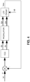
- the electronic system 10 further comprises a modulator (shown for example in Figures 3 and 4 ), configured to receive from the electronic control and processing means digital logic driving signals and to generate and provide to the first switching circuit 16 and to the second switching circuit 15 respective physical driving signals, in accordance with a predefined modulation, characterized by the aforesaid positive branch switching duty-cycle d p and negative branch switching duty-cycle d n , respectively.
- a modulator shown for example in Figures 3 and 4 , configured to receive from the electronic control and processing means digital logic driving signals and to generate and provide to the first switching circuit 16 and to the second switching circuit 15 respective physical driving signals, in accordance with a predefined modulation, characterized by the aforesaid positive branch switching duty-cycle d p and negative branch switching duty-cycle d n , respectively.
- the system comprises a further third switching circuit 18 comprising a third switching unit (comprising for example a third switch SWC), configured to take either one of two states according to a first driving signal having a positive branch switching duty-cycle d p , and a first sample resistance R SWC arranged in series with respect to the aforesaid third switching unit.
- the third switching unit is arranged between the first device terminal 11 and the negative terminal 21 of the energized electrical apparatus.
- the electronic system 10 is configured to perform an insulation resistance measuring method according to any one of the embodiments previously shown.
- the present method aims to measure an insulation loss (LOI-"Loss of Insulation”), i.e., to measure the insulation resistances R ip , R in of the poles of a battery with respect to a ground, for example a reference voltage of the chassis of a vehicle in which the battery is mounted.
- LOI- insulation loss
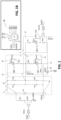
- FIG. 1 The circuit on which the analysis is carried out, in the example illustrated herein, is shown in Figure 1 , in which, in particular, two parts of an insulation resistance measurement device comprising two measurement branches, a positive branch and a negative branch, are indicated.
- the negative branch (previously also referred to as "second switching circuit 15") comprises a negative branch switch SWN switchable to open/close with a negative branch duty-cycle d n placed in parallel with a positive branch switch resistance R swn .
- the negative branch further comprises a measurement circuit 17, which in this implementation option is arranged in parallel with the second switching circuit 15 (considerations completely similar to those reported below also apply, mutatis mutandis, in the alternative implementation option in which the measurement circuit is arranged in parallel with the first switching circuit 16, as easily understood by any person skilled in the art).
- the reference voltage V iso acquired by the converter ADC, varies with a dynamic which depends on circuit parameters and an external load: R ip , R in , C ip and C in .
- the parameter d n is the duty-cycle of the switch of SWN and R swn is the equivalent resistance of the negative switch.
- the parameter d p is the duty-cycle of the switch SWP and R swp is the equivalent resistance of the positive switch.
- V iso 1 V iso
Landscapes
- Physics & Mathematics (AREA)
- General Physics & Mathematics (AREA)
- Chemical & Material Sciences (AREA)
- Engineering & Computer Science (AREA)
- Combustion & Propulsion (AREA)
- Measurement Of Resistance Or Impedance (AREA)
Applications Claiming Priority (1)
| Application Number | Priority Date | Filing Date | Title |
|---|---|---|---|
| IT102022000026010A IT202200026010A1 (it) | 2022-12-20 | 2022-12-20 | Metodo, dispositivo elettronico e sistema per misurare in modo iterativo la resistenza di isolamento di un apparato elettrico energizzato rispetto a massa |
Publications (2)
| Publication Number | Publication Date |
|---|---|
| EP4390425A1 true EP4390425A1 (de) | 2024-06-26 |
| EP4390425B1 EP4390425B1 (de) | 2025-07-16 |
Family
ID=85461900
Family Applications (1)
| Application Number | Title | Priority Date | Filing Date |
|---|---|---|---|
| EP23217286.6A Active EP4390425B1 (de) | 2022-12-20 | 2023-12-15 | Verfahren, elektronische vorrichtung und system zur iterativen messung des isolationswiderstands einer stromgetriebenen elektrischen vorrichtung in bezug auf die erde |
Country Status (5)
| Country | Link |
|---|---|
| US (1) | US12474387B2 (de) |
| EP (1) | EP4390425B1 (de) |
| JP (1) | JP2024088613A (de) |
| CN (1) | CN118226129A (de) |
| IT (1) | IT202200026010A1 (de) |
Citations (5)
| Publication number | Priority date | Publication date | Assignee | Title |
|---|---|---|---|---|
| EP3182146A1 (de) * | 2015-12-18 | 2017-06-21 | Magneti Marelli S.p.A. | Elektronische vorrichtung, system und verfahren für isolierungswiderstandsmessungen mit funktionen zur selbstdiagnose und diagnose von isolierungsverlust bezüglich der erdung einer unter spannung stehenden, elektrischen vorrichtung |
| DE102018116055B3 (de) * | 2018-07-03 | 2019-10-31 | Dr. Ing. H.C. F. Porsche Aktiengesellschaft | Verfahren und Isolationswächter zur widerstandsadaptiven Isolierungsüberwachung |
| US20210041505A1 (en) * | 2019-08-06 | 2021-02-11 | GM Global Technology Operations LLC | Active isolation detection using adaptive bias resistance |
| DE102021106968B3 (de) * | 2021-03-22 | 2022-09-15 | Dr. Ing. H.C. F. Porsche Aktiengesellschaft | Verfahren zur Funktionsüberprüfung eines HV-Systems, HV-System, Kraftfahrzeug |
| DE102021127385B3 (de) * | 2021-10-21 | 2022-11-03 | Dr. Ing. H.C. F. Porsche Aktiengesellschaft | Verfahren zur Plausibilisierung einer Isolationsüberwachung eines Hochvoltsystems eines Elektrofahrzeugs während des Aufladens einer Traktionsbatterie des Elektrofahrzeugs |
Family Cites Families (1)
| Publication number | Priority date | Publication date | Assignee | Title |
|---|---|---|---|---|
| DE102019125982B4 (de) * | 2019-09-26 | 2021-06-10 | Bender Gmbh & Co. Kg | Kombinierte Überwachungsvorrichtung zur Isolationswiderstands- und Schutzleiterwiderstands-Überwachung eines Stromversorgungssystems |
-
2022
- 2022-12-20 IT IT102022000026010A patent/IT202200026010A1/it unknown
-
2023
- 2023-12-15 JP JP2023211995A patent/JP2024088613A/ja active Pending
- 2023-12-15 EP EP23217286.6A patent/EP4390425B1/de active Active
- 2023-12-18 US US18/542,906 patent/US12474387B2/en active Active
- 2023-12-20 CN CN202311761987.4A patent/CN118226129A/zh active Pending
Patent Citations (5)
| Publication number | Priority date | Publication date | Assignee | Title |
|---|---|---|---|---|
| EP3182146A1 (de) * | 2015-12-18 | 2017-06-21 | Magneti Marelli S.p.A. | Elektronische vorrichtung, system und verfahren für isolierungswiderstandsmessungen mit funktionen zur selbstdiagnose und diagnose von isolierungsverlust bezüglich der erdung einer unter spannung stehenden, elektrischen vorrichtung |
| DE102018116055B3 (de) * | 2018-07-03 | 2019-10-31 | Dr. Ing. H.C. F. Porsche Aktiengesellschaft | Verfahren und Isolationswächter zur widerstandsadaptiven Isolierungsüberwachung |
| US20210041505A1 (en) * | 2019-08-06 | 2021-02-11 | GM Global Technology Operations LLC | Active isolation detection using adaptive bias resistance |
| DE102021106968B3 (de) * | 2021-03-22 | 2022-09-15 | Dr. Ing. H.C. F. Porsche Aktiengesellschaft | Verfahren zur Funktionsüberprüfung eines HV-Systems, HV-System, Kraftfahrzeug |
| DE102021127385B3 (de) * | 2021-10-21 | 2022-11-03 | Dr. Ing. H.C. F. Porsche Aktiengesellschaft | Verfahren zur Plausibilisierung einer Isolationsüberwachung eines Hochvoltsystems eines Elektrofahrzeugs während des Aufladens einer Traktionsbatterie des Elektrofahrzeugs |
Also Published As
| Publication number | Publication date |
|---|---|
| US20240201238A1 (en) | 2024-06-20 |
| EP4390425B1 (de) | 2025-07-16 |
| IT202200026010A1 (it) | 2024-06-20 |
| JP2024088613A (ja) | 2024-07-02 |
| CN118226129A (zh) | 2024-06-21 |
| US12474387B2 (en) | 2025-11-18 |
Similar Documents
| Publication | Publication Date | Title |
|---|---|---|
| CN111060791B (zh) | 绝缘故障检测方法、装置、电动汽车、终端设备及介质 | |
| CN106896274B (zh) | 用于绝缘电阻测量和绝缘损耗诊断的装置、系统和方法 | |
| EP3929021B1 (de) | Vorrichtung zur erkennung elektrischer fehler und system zur stromversorgung eines fahrzeugs | |
| US5574355A (en) | Method and apparatus for detection and control of thermal runaway in a battery under charge | |
| US10611243B2 (en) | Ground fault detection apparatus | |
| CN111189645B (zh) | 用于以减少的处理时间执行诊断过程的方法和系统 | |
| US12117502B2 (en) | Earth leakage detection device and vehicle power supply system | |
| KR20080068659A (ko) | 전기 에너지 저장장치의 출력 용량 예측 방법 | |
| US12072393B2 (en) | Leakage detection device and power system for vehicle | |
| KR20170064908A (ko) | 친환경 차량의 절연파괴 검출장치 및 방법 | |
| US11959951B2 (en) | Method for estimating the insulation resistance of a high-voltage circuit in an electric or hybrid motor vehicle | |
| US12210052B2 (en) | Method for detecting an electrical insulation fault between an electric power source and an electrical ground | |
| US20160109500A1 (en) | Methods and apparatus for detecting electrical leakage in a vehicle | |
| US10126344B2 (en) | Method for measuring electrical isolation of a vehicle chassis | |
| CN110361669B (zh) | 电池劣化判定装置 | |
| EP4130761B1 (de) | Vorrichtung zur erkennung von stromleckagen und fahrzeugstromversorgungssystem | |
| EP4390425A1 (de) | Verfahren, elektronische vorrichtung und system zur iterativen messung des isolationswiderstands einer stromgetriebenen elektrischen vorrichtung in bezug auf die erde | |
| US20190214689A1 (en) | Method for detecting an internal short circuit in a first electrical energy storage unit of an electrical energy storage device | |
| US11874332B2 (en) | Failure detection apparatus | |
| US20210018555A1 (en) | Method for determining at least two equivalent insulation resistances of an electric system | |
| US12044749B2 (en) | Electric insulation monitoring arrangement | |
| CN114578134A (zh) | 车辆装置绝缘电阻检测方法、装置、设备及存储介质 | |
| CN109444549A (zh) | 一种车身绝缘的快速检测电路及方法 |
Legal Events
| Date | Code | Title | Description |
|---|---|---|---|
| PUAI | Public reference made under article 153(3) epc to a published international application that has entered the european phase |
Free format text: ORIGINAL CODE: 0009012 |
|
| STAA | Information on the status of an ep patent application or granted ep patent |
Free format text: STATUS: THE APPLICATION HAS BEEN PUBLISHED |
|
| AK | Designated contracting states |
Kind code of ref document: A1 Designated state(s): AL AT BE BG CH CY CZ DE DK EE ES FI FR GB GR HR HU IE IS IT LI LT LU LV MC ME MK MT NL NO PL PT RO RS SE SI SK SM TR |
|
| STAA | Information on the status of an ep patent application or granted ep patent |
Free format text: STATUS: REQUEST FOR EXAMINATION WAS MADE |
|
| 17P | Request for examination filed |
Effective date: 20241007 |
|
| RBV | Designated contracting states (corrected) |
Designated state(s): AL AT BE BG CH CY CZ DE DK EE ES FI FR GB GR HR HU IE IS IT LI LT LU LV MC ME MK MT NL NO PL PT RO RS SE SI SK SM TR |
|
| GRAP | Despatch of communication of intention to grant a patent |
Free format text: ORIGINAL CODE: EPIDOSNIGR1 |
|
| STAA | Information on the status of an ep patent application or granted ep patent |
Free format text: STATUS: GRANT OF PATENT IS INTENDED |
|
| RIC1 | Information provided on ipc code assigned before grant |
Ipc: G01R 31/00 20060101ALI20250203BHEP Ipc: G01R 27/02 20060101ALI20250203BHEP Ipc: G01R 31/52 20200101AFI20250203BHEP |
|
| INTG | Intention to grant announced |
Effective date: 20250212 |
|
| RIN1 | Information on inventor provided before grant (corrected) |
Inventor name: EL GOUMRI, BRAHIM Inventor name: SUGLIA, ROSANNA Inventor name: PATRINOSTRO, SIMONE Inventor name: AURILIO, GIANLUCA |
|
| GRAS | Grant fee paid |
Free format text: ORIGINAL CODE: EPIDOSNIGR3 |
|
| GRAA | (expected) grant |
Free format text: ORIGINAL CODE: 0009210 |
|
| STAA | Information on the status of an ep patent application or granted ep patent |
Free format text: STATUS: THE PATENT HAS BEEN GRANTED |
|
| AK | Designated contracting states |
Kind code of ref document: B1 Designated state(s): AL AT BE BG CH CY CZ DE DK EE ES FI FR GB GR HR HU IE IS IT LI LT LU LV MC ME MK MT NL NO PL PT RO RS SE SI SK SM TR |
|
| REG | Reference to a national code |
Ref country code: GB Ref legal event code: FG4D |
|
| P01 | Opt-out of the competence of the unified patent court (upc) registered |
Free format text: CASE NUMBER: APP_28208/2025 Effective date: 20250612 |
|
| REG | Reference to a national code |
Ref country code: CH Ref legal event code: EP |
|
| REG | Reference to a national code |
Ref country code: DE Ref legal event code: R096 Ref document number: 602023004879 Country of ref document: DE |
|
| REG | Reference to a national code |
Ref country code: IE Ref legal event code: FG4D |
|
| REG | Reference to a national code |
Ref country code: NL Ref legal event code: MP Effective date: 20250716 |
|
| PG25 | Lapsed in a contracting state [announced via postgrant information from national office to epo] |
Ref country code: PT Free format text: LAPSE BECAUSE OF FAILURE TO SUBMIT A TRANSLATION OF THE DESCRIPTION OR TO PAY THE FEE WITHIN THE PRESCRIBED TIME-LIMIT Effective date: 20251117 |
|
| PG25 | Lapsed in a contracting state [announced via postgrant information from national office to epo] |
Ref country code: NL Free format text: LAPSE BECAUSE OF FAILURE TO SUBMIT A TRANSLATION OF THE DESCRIPTION OR TO PAY THE FEE WITHIN THE PRESCRIBED TIME-LIMIT Effective date: 20250716 |
|
| REG | Reference to a national code |
Ref country code: AT Ref legal event code: MK05 Ref document number: 1814482 Country of ref document: AT Kind code of ref document: T Effective date: 20250716 |
|
| PG25 | Lapsed in a contracting state [announced via postgrant information from national office to epo] |
Ref country code: IS Free format text: LAPSE BECAUSE OF FAILURE TO SUBMIT A TRANSLATION OF THE DESCRIPTION OR TO PAY THE FEE WITHIN THE PRESCRIBED TIME-LIMIT Effective date: 20251116 |
|
| PGFP | Annual fee paid to national office [announced via postgrant information from national office to epo] |
Ref country code: DE Payment date: 20251126 Year of fee payment: 3 |
|
| PG25 | Lapsed in a contracting state [announced via postgrant information from national office to epo] |
Ref country code: NO Free format text: LAPSE BECAUSE OF FAILURE TO SUBMIT A TRANSLATION OF THE DESCRIPTION OR TO PAY THE FEE WITHIN THE PRESCRIBED TIME-LIMIT Effective date: 20251016 |
|
| REG | Reference to a national code |
Ref country code: LT Ref legal event code: MG9D |
|
| PG25 | Lapsed in a contracting state [announced via postgrant information from national office to epo] |
Ref country code: AT Free format text: LAPSE BECAUSE OF FAILURE TO SUBMIT A TRANSLATION OF THE DESCRIPTION OR TO PAY THE FEE WITHIN THE PRESCRIBED TIME-LIMIT Effective date: 20250716 |
|
| PG25 | Lapsed in a contracting state [announced via postgrant information from national office to epo] |
Ref country code: FI Free format text: LAPSE BECAUSE OF FAILURE TO SUBMIT A TRANSLATION OF THE DESCRIPTION OR TO PAY THE FEE WITHIN THE PRESCRIBED TIME-LIMIT Effective date: 20250716 |
|
| PG25 | Lapsed in a contracting state [announced via postgrant information from national office to epo] |
Ref country code: HR Free format text: LAPSE BECAUSE OF FAILURE TO SUBMIT A TRANSLATION OF THE DESCRIPTION OR TO PAY THE FEE WITHIN THE PRESCRIBED TIME-LIMIT Effective date: 20250716 |
|
| PGFP | Annual fee paid to national office [announced via postgrant information from national office to epo] |
Ref country code: FR Payment date: 20251120 Year of fee payment: 3 |
|
| PG25 | Lapsed in a contracting state [announced via postgrant information from national office to epo] |
Ref country code: GR Free format text: LAPSE BECAUSE OF FAILURE TO SUBMIT A TRANSLATION OF THE DESCRIPTION OR TO PAY THE FEE WITHIN THE PRESCRIBED TIME-LIMIT Effective date: 20251017 |
|
| PG25 | Lapsed in a contracting state [announced via postgrant information from national office to epo] |
Ref country code: SE Free format text: LAPSE BECAUSE OF FAILURE TO SUBMIT A TRANSLATION OF THE DESCRIPTION OR TO PAY THE FEE WITHIN THE PRESCRIBED TIME-LIMIT Effective date: 20250716 |
|
| PG25 | Lapsed in a contracting state [announced via postgrant information from national office to epo] |
Ref country code: LV Free format text: LAPSE BECAUSE OF FAILURE TO SUBMIT A TRANSLATION OF THE DESCRIPTION OR TO PAY THE FEE WITHIN THE PRESCRIBED TIME-LIMIT Effective date: 20250716 |
|
| PG25 | Lapsed in a contracting state [announced via postgrant information from national office to epo] |
Ref country code: PL Free format text: LAPSE BECAUSE OF FAILURE TO SUBMIT A TRANSLATION OF THE DESCRIPTION OR TO PAY THE FEE WITHIN THE PRESCRIBED TIME-LIMIT Effective date: 20250716 Ref country code: BG Free format text: LAPSE BECAUSE OF FAILURE TO SUBMIT A TRANSLATION OF THE DESCRIPTION OR TO PAY THE FEE WITHIN THE PRESCRIBED TIME-LIMIT Effective date: 20250716 |
|
| PG25 | Lapsed in a contracting state [announced via postgrant information from national office to epo] |
Ref country code: RS Free format text: LAPSE BECAUSE OF FAILURE TO SUBMIT A TRANSLATION OF THE DESCRIPTION OR TO PAY THE FEE WITHIN THE PRESCRIBED TIME-LIMIT Effective date: 20251016 |
|
| PG25 | Lapsed in a contracting state [announced via postgrant information from national office to epo] |
Ref country code: ES Free format text: LAPSE BECAUSE OF FAILURE TO SUBMIT A TRANSLATION OF THE DESCRIPTION OR TO PAY THE FEE WITHIN THE PRESCRIBED TIME-LIMIT Effective date: 20250716 |
|
| PG25 | Lapsed in a contracting state [announced via postgrant information from national office to epo] |
Ref country code: RO Free format text: LAPSE BECAUSE OF FAILURE TO SUBMIT A TRANSLATION OF THE DESCRIPTION OR TO PAY THE FEE WITHIN THE PRESCRIBED TIME-LIMIT Effective date: 20250716 |
|
| PG25 | Lapsed in a contracting state [announced via postgrant information from national office to epo] |
Ref country code: SM Free format text: LAPSE BECAUSE OF FAILURE TO SUBMIT A TRANSLATION OF THE DESCRIPTION OR TO PAY THE FEE WITHIN THE PRESCRIBED TIME-LIMIT Effective date: 20250716 |
|
| PG25 | Lapsed in a contracting state [announced via postgrant information from national office to epo] |
Ref country code: DK Free format text: LAPSE BECAUSE OF FAILURE TO SUBMIT A TRANSLATION OF THE DESCRIPTION OR TO PAY THE FEE WITHIN THE PRESCRIBED TIME-LIMIT Effective date: 20250716 |
|
| PGFP | Annual fee paid to national office [announced via postgrant information from national office to epo] |
Ref country code: IT Payment date: 20251231 Year of fee payment: 3 |
|
| PG25 | Lapsed in a contracting state [announced via postgrant information from national office to epo] |
Ref country code: CZ Free format text: LAPSE BECAUSE OF FAILURE TO SUBMIT A TRANSLATION OF THE DESCRIPTION OR TO PAY THE FEE WITHIN THE PRESCRIBED TIME-LIMIT Effective date: 20250716 |
|
| PG25 | Lapsed in a contracting state [announced via postgrant information from national office to epo] |
Ref country code: EE Free format text: LAPSE BECAUSE OF FAILURE TO SUBMIT A TRANSLATION OF THE DESCRIPTION OR TO PAY THE FEE WITHIN THE PRESCRIBED TIME-LIMIT Effective date: 20250716 Ref country code: SK Free format text: LAPSE BECAUSE OF FAILURE TO SUBMIT A TRANSLATION OF THE DESCRIPTION OR TO PAY THE FEE WITHIN THE PRESCRIBED TIME-LIMIT Effective date: 20250716 |