EP4390592A1 - Prädiktive vorrichtungswartung mit fehlerprotokollierung mehrerer vorrichtungen - Google Patents
Prädiktive vorrichtungswartung mit fehlerprotokollierung mehrerer vorrichtungen Download PDFInfo
- Publication number
- EP4390592A1 EP4390592A1 EP22215430.4A EP22215430A EP4390592A1 EP 4390592 A1 EP4390592 A1 EP 4390592A1 EP 22215430 A EP22215430 A EP 22215430A EP 4390592 A1 EP4390592 A1 EP 4390592A1
- Authority
- EP
- European Patent Office
- Prior art keywords
- building infrastructure
- failure
- building
- devices
- monitoring device
- Prior art date
- Legal status (The legal status is an assumption and is not a legal conclusion. Google has not performed a legal analysis and makes no representation as to the accuracy of the status listed.)
- Pending
Links
Images




Classifications
-
- G—PHYSICS
- G05—CONTROLLING; REGULATING
- G05B—CONTROL OR REGULATING SYSTEMS IN GENERAL; FUNCTIONAL ELEMENTS OF SUCH SYSTEMS; MONITORING OR TESTING ARRANGEMENTS FOR SUCH SYSTEMS OR ELEMENTS
- G05B23/00—Testing or monitoring of control systems or parts thereof
- G05B23/02—Electric testing or monitoring
- G05B23/0205—Electric testing or monitoring by means of a monitoring system capable of detecting and responding to faults
- G05B23/0218—Electric testing or monitoring by means of a monitoring system capable of detecting and responding to faults characterised by the fault detection method dealing with either existing or incipient faults
- G05B23/0224—Process history based detection method, e.g. whereby history implies the availability of large amounts of data
- G05B23/0227—Qualitative history assessment, whereby the type of data acted upon, e.g. waveforms, images or patterns, is not relevant, e.g. rule based assessment; if-then decisions
- G05B23/0237—Qualitative history assessment, whereby the type of data acted upon, e.g. waveforms, images or patterns, is not relevant, e.g. rule based assessment; if-then decisions based on parallel systems, e.g. comparing signals produced at the same time by same type systems and detect faulty ones by noticing differences among their responses
-
- G—PHYSICS
- G05—CONTROLLING; REGULATING
- G05B—CONTROL OR REGULATING SYSTEMS IN GENERAL; FUNCTIONAL ELEMENTS OF SUCH SYSTEMS; MONITORING OR TESTING ARRANGEMENTS FOR SUCH SYSTEMS OR ELEMENTS
- G05B23/00—Testing or monitoring of control systems or parts thereof
- G05B23/02—Electric testing or monitoring
- G05B23/0205—Electric testing or monitoring by means of a monitoring system capable of detecting and responding to faults
- G05B23/0218—Electric testing or monitoring by means of a monitoring system capable of detecting and responding to faults characterised by the fault detection method dealing with either existing or incipient faults
- G05B23/0224—Process history based detection method, e.g. whereby history implies the availability of large amounts of data
- G05B23/0227—Qualitative history assessment, whereby the type of data acted upon, e.g. waveforms, images or patterns, is not relevant, e.g. rule based assessment; if-then decisions
- G05B23/0235—Qualitative history assessment, whereby the type of data acted upon, e.g. waveforms, images or patterns, is not relevant, e.g. rule based assessment; if-then decisions based on a comparison with predetermined threshold or range, e.g. "classical methods", carried out during normal operation; threshold adaptation or choice; when or how to compare with the threshold
-
- G—PHYSICS
- G05—CONTROLLING; REGULATING
- G05B—CONTROL OR REGULATING SYSTEMS IN GENERAL; FUNCTIONAL ELEMENTS OF SUCH SYSTEMS; MONITORING OR TESTING ARRANGEMENTS FOR SUCH SYSTEMS OR ELEMENTS
- G05B23/00—Testing or monitoring of control systems or parts thereof
- G05B23/02—Electric testing or monitoring
- G05B23/0205—Electric testing or monitoring by means of a monitoring system capable of detecting and responding to faults
- G05B23/0218—Electric testing or monitoring by means of a monitoring system capable of detecting and responding to faults characterised by the fault detection method dealing with either existing or incipient faults
- G05B23/0256—Electric testing or monitoring by means of a monitoring system capable of detecting and responding to faults characterised by the fault detection method dealing with either existing or incipient faults injecting test signals and analyzing monitored process response, e.g. injecting the test signal while interrupting the normal operation of the monitored system; superimposing the test signal onto a control signal during normal operation of the monitored system
-
- H—ELECTRICITY
- H05—ELECTRIC TECHNIQUES NOT OTHERWISE PROVIDED FOR
- H05B—ELECTRIC HEATING; ELECTRIC LIGHT SOURCES NOT OTHERWISE PROVIDED FOR; CIRCUIT ARRANGEMENTS FOR ELECTRIC LIGHT SOURCES, IN GENERAL
- H05B47/00—Circuit arrangements for operating light sources in general, i.e. where the type of light source is not relevant
- H05B47/20—Responsive to malfunctions or to light source life; for protection
- H05B47/21—Responsive to malfunctions or to light source life; for protection of two or more light sources connected in parallel
- H05B47/22—Responsive to malfunctions or to light source life; for protection of two or more light sources connected in parallel with communication between the lamps and a central unit
Definitions
- the invention concerns the field of building infrastructure, failure localization in building infrastructure and predictive maintenance for devices of building infrastructure.
- localizing and predicting failures in devices of the building infrastructure and a corresponding building infrastructure including a monitoring system is presented.
- Building infrastructures which usually includes a large number of electronic devices arranged over the building. Building infrastructures may include lighting systems, emergency lighting systems, escape route guiding systems, and heating and ventilation (HVAC) systems in order to name just a few examples.
- HVAC heating and ventilation
- a lighting system includes a plurality of different devices, the most prominent of which are lighting modules, which emit light, light driver devices, which generate a load current from mains supply of the site and provide the generated load current to the lighting modules, and control devices of different types.
- a communication network may connect the control devices with the light driver devices, in order to enable the control devices to control light emission by the lighting modules and to collect status messages and failure messages from the light drives devices and lighting modules.
- the control devices may include, or be connected with, a monitoring device, which monitors the operational status of the individual devices of the lighting system, based on, for example, received status messages and error messages.
- Fig. 2 of the attached drawings illustrates a simplified structure of an exemplary lighting system.
- PCB printed circuit boards
- a building infrastructure comprises a plurality of building infrastructure devices and a monitoring device, which are connected by a communication network.
- the monitoring device is configured to determine, in response to receiving a failure message from one building infrastructure device of the plurality of building infrastructure devices, whether at least one further building infrastructure device of the plurality of building infrastructure devices has a corresponding failure as the building infrastructure device.
- the monitoring device is configured to determine that a failure cause for the failure is a common environmental influence of the building infrastructure device and the at least one further building infrastructure device in case the at least one further building infrastructure device has the corresponding failure as the building infrastructure device.
- the monitoring device is furthermore configured to determine that a failure cause for the failure is a local failure of the building infrastructure device, in case the at least one further building infrastructure device has a different failure as the building infrastructure device or no failure at all.
- Current approaches for failure prediction in a building infrastructure device base on counting a runtime of the building infrastructure device and on calculating, and in particular predicting a remaining lifetime of electronic components, e.g. of electrolytic capacitors based on the counted runtime of the building infrastructure device .
- Current building infrastructures do not determine a cause for an error message generated in the building infrastructure.
- the building infrastructure according to the first aspect introduces a differentiation between causes for shutdown of building infrastructure devices. Identifying a specific failure cause enables the building infrastructure to predict a possible total dropout rate in the future for the complete building infrastructure.
- the monitoring device determines an event like receiving an error notification from at least one the building infrastructure devices, the monitoring device acquires from all building infrastructure devices connected via the communication network status information.
- the monitoring device may now determine whether the other building infrastructure devices of the building infrastructure also raised an error notification. Moreover, the monitoring device determines further whether the other building infrastructure devices raised a same type of error in the notification or a different type of error notification.
- a same type of error or corresponding failure can be determined from a look up table for example, in which failures are associated for which it is known that they typically occur as a result of the same external (environmental) influence, for example overvoltage or high ambient temperatures.
- the monitoring device now is enabled to conclude which kind of error, e.g.
- an internal error of the at least one building infrastructure device transmitting the error notification initially, or potentially an error having a common error cause due to an environmental influence on a number of building infrastructure devices is present.
- the building infrastructure devices had been or are being exposed to an overvoltage on the mains supply line, or short voltage spikes on the mains supply line, for example, which might shorten their lifetime considerably.
- a sudden temperature rise over a part of the site including a plurality of building infrastructure devices of the building infrastructure may be determined as the cause for the initial failure notification of the building infrastructure device, which may then spread to further building infrastructure devices arranged in the vicinity of the building infrastructure device.
- the monitoring device may assume what the cause for the current failure notification was.
- a building infrastructure device may shut down and notify the monitoring device via the communication network of the shutdown due to a DC bus undervoltage on a DC bus generated and provided by a PFC circuit of the building infrastructure device.
- the undervoltage on the DC voltage line may caused by two different failure mechanisms.
- failure cause is an interruption of a mains supply to the respective building infrastructure device notifying the undervoltage on the DC bus line.
- An alternative failure cause may result from an internal device failure, for example due to an electronic component in the control loop circuitry of a power factor correction circuit (PFC) circuit stage of the building infrastructure device generating the DC bus voltage reaching its end-of-life and failing.
- This second failure mechanism is an internal failure of the building infrastructure device providing the failure notification.
- the monitoring device If, however also another building infrastructure device is shutting down with the corresponding failure notification to the monitoring device referring to a DC bus undervoltage failure, the monitoring device is able to conclude that the failure notification of both building infrastructure devices was caused by a same failure cause, most probably a mains failure. In consequence, the monitoring device may output information suggesting to a technician the determined failure cause and a potential shutdown of further building infrastructure devices due to the same failure cause, although up to now no respective failure message was received from those further building infrastructure devices of the building infrastructure.
- a voltage surge pulse may trigger an overvoltage detection function in a load circuit of a building infrastructure device, e.g. a light driver, which protects a lighting module.
- the monitoring device may determine that a failure cause for the failure is in a common environmental influence of the building infrastructure device, e.g. by an event on a mains supply line due to the at least one further building infrastructure device having the corresponding failure of triggering the overvoltage protection function in the load circuit as the building infrastructure device shows.
- the monitoring device is therefore able to exclude a local failure, e.g. a LED failure in the lighting module, and determine that the failure cause for the failure is a voltage surge pulse caused by a mains failure, which causes the corresponding failure in other building infrastructure devices of the plurality of building infrastructure devices also.
- Predicting the failure cause by the monitoring device in the building infrastructure provides the advantage that further effects on the building infrastructure device become predictable: e.g. a field application in an environment in which numerous mains voltage surges occur, a lifetime of circuit components such as mains VDR of the plurality of building infrastructure devices exposed to these mains voltage surges may be expected to decrease.
- the monitoring device and a control and management of the building infrastructure may schedule regular checks of building infrastructure devices, which may be affected by the mains voltage surges. This targeted increase in maintenance of the building infrastructure may decrease the time for which building infrastructure devices are down with a failure and waiting for repair or replacement, thereby increasing availability of the building infrastructure.
- the common environmental influence includes at least one of a mains supply failure and a temperature event.
- a temperature event may be exceeding an upper threshold or falling below a lower threshold defining an intended operating range for the ambient temperature.
- Such a temperature range can be defined in the technical specification of the infrastructure device.
- Failure causes originating in the mains supply or due to excessive ambient temperatures are examples, in which the improved use of available data by the monitoring device helps to improve determining failure causes more precisely without adding further sensors into the plurality of building infrastructure devices and increasing complexity and cost of the individual building infrastructure device, and therefore system cost of the building infrastructure disproportionally.
- the plurality of building infrastructure devices may include a plurality of driver devices, in particular a plurality of light driver devices.
- Each driver device of the plurality of driver devices may include a power factor correction (PFC) circuit and a DC/DC-converter circuit.
- PFC power factor correction
- the plurality of building infrastructure devices may be configured to generate a load current for driving an electric load based on a mains power supply.
- the electric load may include at least one lighting module, which is supplied by the light driver device with the load current (LED current).
- Lighting systems including a plurality of building infrastructure devices providing a load current (LED current) for a plurality of lighting modules are a widespread application for the building infrastructure and may benefit from the additional possibilities provided by the building infrastructure.
- LED current load current
- An embodiment of the building infrastructure device show the failure message (error message) indicating an error shutdown of the building infrastructure device.
- the failure message may indicate a failure category of the determined failure, wherein the failure category includes at least a mains failure, a building infrastructure device failure and a load failure.
- the infrastructure device comprises a device failure analysis unit configured to acquire reference parameter values corresponding to a reference operation state of the respective building infrastructure device. Furthermore, the device failure analysis unit is configured to control the building infrastructure device to switch into the reference operation state.
- the device failure analysis unit is configured to read current parameter values the building infrastructure device, and to evaluate the current parameter values with the reference parameter values, which may be stored in an error mapping file, in order to generate output data, and to provide the generated output data to an output device.
- the output device is configured to transmit the output data to at least one of a predictive maintenance device or a user interface for presenting the output data to a user. In order to be sure that the obtained parameters can be compared to each other, the current parameters values are obtained in the reference operation state for which also the reference parameter values were acquired.
- the device failure analysis unit may be included in the monitoring device or the infrastructure device.
- the device failure analysis unit may be able to detect problems within a luminaire even before the entire luminaire fails, is shutting down or even destroyed, based on parameters such as an ON-time of switches in DC/DC-converter circuits implemented in a switched-mode power supply (SMPS) topology, or measured voltages and currents of individual circuit stages in the building infrastructure device.
- SMPS switched-mode power supply
- the plurality of parameters may include at least one of input signals and output signals of internal electric circuits of the plurality of building infrastructure devices.
- the plurality of parameters may include infrastructure measured signal values (measured signal values) including at least one of measured voltage amplitudes and current amplitudes.
- the plurality of parameters may include infrastructure control signal values (control signal values) that include at least one of a length of a period in which a switch control signal switches a switch into a conducting state or a duty cycle of the switch control signal.
- infrastructure control signal values control signal values
- DC/DC-converter circuits are part of many devices of building infrastructure devices.
- the plurality of parameters may include at least one of infrastructure measurement signal values (measurement signals) generated based on a process variable (manipulated variable) of a control loop, process variable values of the control loop, and control signal values output by a controller of the control loop.
- infrastructure measurement signal values measured based on a process variable (manipulated variable) of a control loop
- process variable values of the control loop and control signal values output by a controller of the control loop.
- Control loop architectures are regularly implemented in electronic circuits of building infrastructure devices.
- the monitoring device is configured to evaluate the current parameter values and the reference parameter values, which are stored previously.
- the evaluations may include determining whether a PFC circuit, a DC/DC-converter circuit, or measurement circuits associated with the PFC circuit or the DC/DC-converter circuit respectively show a failure.
- the measurements circuits may include at least one of a resistance divider network and a measurement coil.
- the control circuit of the building infrastructure device or the monitoring device may now detect, whether a resistor in the control loop feedback is failing.
- the reference parameter values include information on the initial state of building infrastructure device when it is operated in the reference operation state, e.g. after a factory acceptance test or after first time start up. A deterioration of the state of building infrastructure device over time in the filed becomes detectable by a computationally advantageous comparison of current parameter values with the reference parameter values stored in the error-mapping file.
- the reference parameter values may be obtained for a specific type of building infrastructure device, or acquired as a device-specific reference parameter values for each building infrastructure device individually. The latter may be achieve by conducting a respective measurement in the reference operation state, which could be set directly after the device is powered up for the first time or at the end of a function check at the end of the manufacturing process.
- Determining and using the reference parameter values valid for a plurality of building infrastructure devices of a same device type simplifies manufacturing of the building infrastructure devices with regard to time and cost.
- generating and using the device-specific reference parameter values for each individual building infrastructure device provides a more detailed prediction capability for each building infrastructure device in the field taking into account site-specific environmental influence.
- the plurality of building infrastructure devices of the building infrastructure may each include a memory circuit configured to store the reference parameter values.
- a building infrastructure device including the device failure analysis unit may comprises the capability to manage the reference parameter values, and therefore the standard based on which to determine the current state of the building infrastructure device locally. Replacing a building infrastructure device, in particular replacing a building infrastructure device with another building infrastructure device of a different type is easily possible, without requiring updating the reference parameter values at a monitoring server in the field to adapt to the other building infrastructure device of the different type, which may have different parameter and/or different parameter values.
- the plurality of building infrastructure devices each include a device failure analysis unit (e.g. integrated in a control circuit) configured to evaluate the actual parameter values and the reference parameter values stored in an internal memory of the infrastructure device or retrieved from an external memory that may be included in the monitoring device.
- a device failure analysis unit e.g. integrated in a control circuit
- a control circuit of the building infrastructure device is able to perform the evaluating the parameter values, the monitoring and failure analysis and failure prediction locally.
- the monitoring device of an embodiment of the building infrastructure may include a data storage unit configured to store the reference parameter values, which is in particular advantageous in case that the device failure analysis unit is included in the monitoring device.
- the monitoring device may perform a combined data analysis for the plurality of building infrastructure devices based on the reference parameter values of the plurality of building infrastructure devices.
- the monitoring device is configured to switch the building infrastructure device into the reference operation state each time after a predefined interval has elapsed.
- the evolvement of the state of the plurality of building infrastructure devices over time starting from the original (reference) state of the plurality of building infrastructure devices recorded by storing the reference parameter values is determinable.
- Predicting a future development of the building infrastructure e.g. predicting future failures of devices, or scheduling of maintenance measures is possible implementing methods of predictive maintenance in the building infrastructure.
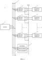
- Fig. 1 shows a simplified flowchart of an exemplary process of handling a fault message in the building infrastructure 1 according to an embodiment.
- the simplified structure of the building infrastructure 1 will be discussed in more detail with reference to fig. 2 .
- the building infrastructure 1 may be a lighting system.
- the plurality of building infrastructure devices 2.i may include a plurality of light driver devices.
- step S1 the monitoring device 7 receives a failure message from a building infrastructure device 2.i of the plurality of building infrastructure devices 2.i.
- the monitoring device 7 may receive a corresponding failure message or different failure messages from plural building infrastructure devices 2.i of the plurality of building infrastructure devices 2.i.
- step S2 the monitoring device 7 determines, in response to receiving the failure message from one building infrastructure device 2.i of the plurality of building infrastructure devices 2.i, whether at least one further building infrastructure device 2.i of the plurality of building infrastructure devices 2.i provides a corresponding failure message.
- the monitoring device 7 determines in step S3, whether the failure message received in step S1 from the building infrastructure device 2.i corresponds to at least one existing failure message received from at least one other building infrastructure device 2.i.
- step S3 determines in case the monitoring device 7 determines in step S3, that the at least one other building infrastructure device 2.i has a different failure as the building infrastructure device 2.i, or the at least one other building infrastructure device 2.i has no failure as the building infrastructure device 2.i at all, the monitoring device proceeds to step S4.
- the monitoring device 7 determines that a failure cause for the failure is an internal cause of the building infrastructure device 2.i, as the at least one further building infrastructure device 2.i shows a different failure as the building infrastructure device 2.i, or the at least one further building infrastructure device 2.i has no failure as the building infrastructure device 2.i at all.
- step S5 the monitoring device 7 generates a test report that includes that the failure notified to the monitoring device 7 is a local failure of the building infrastructure device 2.i.
- step S3 determines in case the monitoring device 7 determines in step S3, that the at least one other building infrastructure device 2.i has a corresponding failure as the building infrastructure device 2.i, the monitoring device proceeds to step S6.
- step S6 the monitoring device 7 determines that a failure cause for the failure is in a common environmental influence on the building infrastructure device 2.i. and the at least one further building infrastructure device 2.i as the at least one other building infrastructure device 2.i has the corresponding failure as the building infrastructure device 2.i. For a plurality of devices, such corresponding failures are determined to be the same failures, because identical devices will identically respond to same environmental influences.
- step S5 the monitoring device 7 generates a test report that includes that the failure notified to the monitoring device 7 has an environmental failure cause affecting plural building infrastructure devices 2.i or all building infrastructure devices 2.i of the plurality of building infrastructure devices 2.i.
- the environmental failure cause may be a global influence, affecting plural building infrastructure devices 2.i or all building infrastructure devices 2.i of the plurality of building infrastructure devices 2.i of the building infrastructure 1.
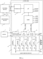
- Fig. 2 provides an overview over the structure of an exemplary building infrastructure 1.
- a mains supply device 5 provides electric power via a mains supply 4, e.g. an AC mains supply voltage, to the devices of the building infrastructure 1.
- a mains supply 4 e.g. an AC mains supply voltage
- the light driver devices each generate and output a LED current I LED as a DC current via load terminals LED+ and LED- to a lighting module connected via the load terminals LED+ and LED- to the light driver device.
- the building infrastructure 1 further comprises a communication network 6.
- the communication network 6 of the lighting system is shown as a bus system, which enables a bidirectional communication between the light driver devices on the one hand and a control, monitoring and light management facility on the other hand.
- the communication network 6 may comprise at least one of a wired communication bus or a wireless communication bus.
- the control, monitoring and light management facility may include a control device 8 that controls operation of the light driver devices and the lighting modules.
- the control, monitoring and light management facility may include a monitoring device 7 that monitors operation of the light driver devices and the lighting modules.
- the control, monitoring and light management facility may receive status messages, e.g. status messages reporting a current operational status of each light driver device, or a failure message from the devices connected via the communication network 6 with the control, monitoring and light management facility.
- the control, monitoring and light management facility 7 may request status messages such as status messages reporting a current operational status of each light driver device, or a respective failure message from of each light driver device connected via the communication network 6 with the control, monitoring and light management facility 7.
- the control, monitoring and light management facility 7 may include input/output devices providing a user interface, which enable a user or technician to access operational data of the lighting system, control operation of the lighting system, or schedule maintenance of the lighting system, for example.
- the control, monitoring and light management facility 7 may include a data storage unit that stores data for operation of the lighting system.
- the stored data may include a file that includes reference parameter values of a plurality of parameters recorded associated with each light driver device when operated in a reference operation state.
- the stored data may include at least one file includes reference parameter values of a plurality of parameters recorded associated with a specific type of light driver device.
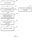
- Fig. 3 provides a simplified block diagram of a luminaire 10 in the building infrastructure 1 according to an embodiment.
- the luminaire 10 includes a light driver device 2 (LED driver) and a lighting module 3.
- the light driver device 2 generates the LED current I LED at a LED voltage V LED and outputs the LED current I LED via the load terminals LED+ and LED- to the lighting module 3.
- the lighting module 3 may include a plurality of light emitting diodes (LED) electrically connected in a series and/or parallel circuit topology to the load terminals LED+ and LED- of the light driver device 2.
- LED light emitting diodes
- the light driver device 2 of fig. 3 shows a mains supply interface connected to the mains supply 4 of the site, e.g. a mains supply grid of a building.
- the mains supply 4 may provide mains supply via an AC mains supply voltage to the luminaire 10 and its subassemblies, in particular to the light driver 2.
- Fig. 3 shows the light driver 2 of fig. 3 only with some of its functional elements, illustrated are, for example, an EMI filter and rectifier circuit 14 (EMI filter and rectifier circuit stage 14), a PFC circuit 15 (PFC circuit stage 15 ) and a DC/DC-converter circuit 16 (DC/DC-converter stage 16) in a main power path of the light driver 2.
- EMI filter and rectifier circuit stage 14 EMI filter and rectifier circuit stage 14
- PFC circuit 15 PFC circuit stage 15
- DC/DC-converter circuit 16 DC/DC-converter stage 16
- the mains supply interface obtains a mains supply current I AC,MAINS at the AC mains supply voltage V AC and provides the mains supply current I AC,MAINS to the EMI filter and rectifier circuit 14, which performs filtering and rectification functions on the AC mains supply voltage V AC and the AC mains supply current I AC,MAINS .
- a measurement circuit including a shunt resistor R 1 and a resistive divider network comprising the resistors R2 and R2_H connected in series is arranged associated with the EMI filter and rectifier circuit 14.
- the measurement circuit Via the shunt resistor R1, the measurement circuit provides a measurement signal I_MAINS, whose value is representative for, e.g. proportional to, the mains supply current I AC,MAINS .
- the measurement circuit Via the resistive divider network comprising the resistors R2 and R2_H, the measurement circuit provides a measurement signal V_MAINS, whose value is representative for, e.g. proportional to, the mains supply voltage V AC,MAINS .
- the measurement circuit provides the measurement signals I_MAINS and V_MAINS to a control circuit of the light driver device 2.
- the control circuit may include at least one integrated circuit (IC).
- IC integrated circuit
- ASIC application specific integrated circuit
- the measurement circuit provides the measurement signals I_MAINS and V_MAINS to the microcontroller circuit 11, in particular to analogue inputs of the microcontroller circuit 11.
- the microcontroller circuit 11 may perform mains supply monitoring based on the obtained measurement signals I_MAINS and V_MAINS.
- the EMI filter and rectifier circuit 14 provides the filtered and rectified AC mains supply voltage V AC and the AC mains supply current I AC, MAINS to the subsequent PFC circuit 15 arranged thereafter in the main power path of the light driver device 2.
- the PFC circuit 15 performs power factor correction, e.g. changes a waveform of the current drawn by a load.
- the PFC circuit 15 may perform active power factor correction using a buck converter topology, boost converter topology or buck-boost converter topology as typical examples of SMPS with a switch controlled by a switch control signal PFC_CTRL
- a further measurement circuit including a shunt resistor R3 and a resistive divider network comprising the resistors R4 and R4_H connected in series is arranged associated with the PFC circuit 15.
- the measurement circuit Via the shunt resistor R3, the measurement circuit provides a measurement signal I_PFC, whose value is representative for, e.g. proportional to, a current I PFC provided by the PFC circuit 15.
- the further measurement circuit provides a measurement signal V_BUS, whose value is representative for, e.g. proportional to, a DC bus voltage V BUS generated and output by the PFC circuit 15.
- the further measurement circuit associated with the PFC circuit 15 provides the measurement signals I_PFC and V_BUS to the control circuit of the light driver device 2.
- the further measurement circuit provides the measurement signals I_PFC and V_BUS to the ASIC 12, in particular to analogue inputs of the ASIC 12.
- the ASIC 12 may perform generating the switch control signal PFC_CTRL based on the obtained measurement signals I_PFC and V_BUS.
- the ASIC 12 provides the generated switch control signal PFC_CTRL to the PFC circuit 15.
- the PFC circuit 15, the further measurement circuit associated with the PFC circuit 15, and the ASIC 12 implement a control loop for controlling the DC bus voltage V BUS and the current I PFC provided by the PFC circuit 15.
- the PFC circuit 15 provides the DC bus voltage V BUS and the current I PFC to the subsequent DC/DC-converter circuit 16 arranged thereafter in the main power path of the light driver device 2.
- the DC/DC-converter circuit 16 generates the DC load voltage V LED and the DC load current I LED based on the DC bus voltage V BUS .
- the DC/DC-converter circuit 16 provides the DC load voltage V LED and the DC load current I LED via the load terminals LED+ and LED- to the lighting module 3.
- the PFC circuit 15 may have a SMPS circuit topology including at least one controlled switch, e.g. a buck converter topology, boost converter topology or buck-boost converter topology as typical examples of SMPS with a switch controlled by a switch control signal DC/DC_CTRL provided by a the ASIC 12.
- a SMPS circuit topology including at least one controlled switch, e.g. a buck converter topology, boost converter topology or buck-boost converter topology as typical examples of SMPS with a switch controlled by a switch control signal DC/DC_CTRL provided by a the ASIC 12.
- a further measurement circuit associated with the DC/DC-converter circuit 16 includes a shunt resistor R5 and a resistive divider network comprising the resistors R6 and R6_H connected in series.
- the further measurement circuit provides a measurement signal I_LED, whose value is representative for, e.g. proportional to, the load current I LED provided by the DC/DC-converter circuit 16.
- the further measurement circuit provides a measurement signal V_LED, whose value is representative for, e.g. proportional to, the DC load voltage V LED generated between the load terminals LED+ and LED-.
- the further measurement circuit associated with the DC/DC-converter circuit 16 provides the measurement signals I_LED and V_LED to the control circuit of the light driver device 2.
- the further measurement circuit provides the measurement signals I_LED and V_LED to the ASIC 12, in particular to further analogue inputs of the ASIC 12.
- the ASIC 12 may generate the switch control signal DC/DC_CTRL based on the obtained measurement signals I_LED and V_LED.
- the ASIC 12 provides the generated switch control signal DC/DC_CTRL to the DC/DC-converter circuit 16 for controlling the at least one switch of the DC/DC-converter circuit 16 implemented in a SMPS circuit topology.
- the DC/DC-converter circuit 16 implements a further control loop.
- the measured signals I_MAINS, V_MAINS, I_PFC, V_BUS, I_LED, V_LED (infrastructure measured signals) each are parameters of the light driver device 2.
- the plurality of parameters of the light driver device 2 may further include timing information of the control signals PFC_CTRL and DC/DC_CTRL (infrastructure control signals).
- the timing information of the control signals PFC_CTRL and DC/DC_CTRL may include a respective duration of an ON-time of each of the switches of the PFC circuit 15 and the DC/DC-converter circuit 16.
- An ON-time of switch may be understood as the time the switch is in a conducting state.
- the timing information of the control signals PFC_CTRL and DC/DC_CTRL may include a duty cycle of the switches of the PFC circuit 15 and the DC/DC-converter circuit 16.
- the light driver device 2 shown in fig. 3 further comprises a communication interface 13, which enables the control circuit to perform bidirectional communication via the communication network 6 with a control device 8 and the monitoring device 7 of a lighting system.
- the monitoring device 7 may be integrated with the control device 8 or may be implemented as a separate device with respect to the control device 8.
- bus 9 may provide a communication link between the control device 8 and the monitoring device 7.
- Fig. 4 illustrates a first example of a process of determining a failure cause in a building infrastructure 1 of an embodiment.
- the process is explained mentioning the steps being executed i general by the monitoring device 7, which then needs to comprise the device failure analysis unit.
- the upper portion of fig. 4 shows process steps for generating the file storing the reference parameter values in an error mapping preparation phase.
- the building infrastructure device 2, 2.i may operate in a operation phase.
- Fig. 4 illustrates the case that while the building infrastructure device 2, 2.i is operating in a standard operational mode in the standard operation phase, a failure occurs and, based on the detected failure, a failure notification is generated and output. In response to the failure notification, the building infrastructure device 2, 2.i switches from the standard operational mode into the failure logging mode. Process steps of the building infrastructure device 2, 2.i operating in the failure logging mode in a failure logging phase after the failure notification is generated and output are in the lower portion of the flowchart of fig. 4 .
- step S41 the monitoring device 7 acquires reference parameter values for a plurality of parameters from each building infrastructure device 2, 2.i of the plurality of building infrastructure devices 2, 2.i.
- step S42 the monitoring device 7 generates a file storing the reference parameter values.
- step S43 the monitoring device 7 stores the generated error mapping file.
- the monitoring device 7 controls the plurality of building infrastructure devices 2, 2.i to switch into an error-mapping mode (failure logging mode).
- the monitoring device 7 controls the building infrastructure devices 2, 2.i to acquire read current parameter values of the plurality of parameters from the plurality of building infrastructure devices 2, 2.i in step S44.
- step S45 succeeding to step S44, the monitoring device 7 reads the reference parameter values from the memory.
- step S46 the monitoring device 7 evaluates the current parameter values based on the reference parameter values stored to generate output data, and to provide the generated output data to an output device.
- the output data may comprise a failure logging notification.
- step S47 the monitoring device 7 transmits the output data to at least one of a predictive maintenance device, e.g. for scheduling a maintenance action appropriate in response to the failure logging notification, or to a user interface for presenting the output data to a user.
- a predictive maintenance device e.g. for scheduling a maintenance action appropriate in response to the failure logging notification
- a user interface for presenting the output data to a user.
- Fig. 5 illustrates an example of a process of determining an error cause in the building infrastructure 1 of the embodiment.
- Fig. 5 shows a specific processing example for the building infrastructure device 2, 2.i, which includes the DC/DC-converter circuit 16.
- step S51 the monitoring device 7 determines that the the ON-time of the switch control signal DC/DC_CTRL is different.
- the monitoring device 7 proceeds in step S51 by starting a check of the DC/DC-converter circuit 16.
- step S52 the monitoring device 7, the building infrastructure device 2, 2.i and the DC/DC-converter circuit 16 is set to operate in a predetermined reference operation state.
- step S53 a regulator for generating the switch control signal DC/DC_CTRL for the switch of the DC/DC-converter circuit 16 is frozen, in particular that the control loop for controlling the DC/DC-converter circuit 16 ceases control of the load current I LED and instead maintains the parameters of the control loop for the set reference operation state.
- step S54 the monitoring device 7 acquires the current parameter values of the plurality of parameters of the DC/DC-converter circuit 16.
- step S55 succeeding to step S54, the monitoring device 7 calculates components values of passive components of the DC/DC-converter circuit 16 based on the acquired parameter values and the known structure of the DC/DC-converter circuit 16.
- the monitoring device 7 determines whether the calculated component values of step S55 correspond, in particular are equal to stored component values of the components available to the monitoring device 7.
- the stored values of the components may be recorded in the file storing the reference parameter values.
- step S56 provides the result that the calculated component values of step S55 correspond to the stored component values of the components (YES)
- the process proceeds to step S58.
- step S58 the monitoring device 7 determines that the sensing path of the control loop has a failure, in particular, that the measurement circuit for measuring the load current I LED and generating the measurement signal I_LED representative for the load current I LED has a failure.
- step S58 proceeds from step S58 to step S59 and outputs a notification of a failure of the I LED measurement circuit, e.g. an I LED voltage divider.
- step S56 provides the result that the calculated component values calculated in step S55 differ from the stored component values of the components (NO), the process proceeds to step S57 and determines that DC/DC-converter circuit 16 has a failure.
- Fig. 6 illustrates a further example of a process of determining a failure cause in the building infrastructure 1 of the embodiment.
- step S60 the monitoring device 7 determines that the current value of the parameter V_LED is different.
- the monitoring device 7 acquires the current parameter values of the plurality of parameters of the building infrastructure device 2, 2.i, and in particular of the DC/DC-converter circuit 16.
- the monitoring device 7 proceeds in step S61 by determining whether other current parameter values of the plural parameters are different to the parameter values stored in the error mapping file.
- step S61 the monitoring device 7 determines that no other current parameter values of the plural parameters differ from the reference parameter values stored in the file (NO), the process proceeds to step S62.
- step S62 it is concluded that the measurement circuit for measuring the current value of the parameter V_LED, which represents the load voltage V LED does not operate according to its intended function.
- the voltage divider including the resistors R and R6_H of the measurement circuit illustrated in fig. 3 may have a failure.
- step S62 the monitoring device ends the processing and outputs a failure notification including an information a failure of the V_LED measurement circuit.
- step S61 the monitoring device 7 determines that other current parameter values of the plural parameters differ from the parameter values stored in the error-mapping file (YES), the process proceeds to step S63
- step S63 the monitoring device 7 determines whether the control signal DC/DC_CTRL for the switch of the DC/DC-converter circuit 16 is different from a respectively stored parameter value of the plurality of parameters.
- step S63 the monitoring device 7 determined that the control signal for the switch of the DC/DC-converter circuit 16 is different from a respectively stored parameter value of the plurality of parameters, the process proceeds to step S64.
- step S64 the monitoring device 7 determines whether the lighting module 3, 3.i has a different input voltage V LED .
- the process proceeds to step S65 and concludes that the lighting module 3, 3.i has a failure and does not operate according to its intended function, e.g. one or more LEDs of the lighting module may be defective.
- the monitoring device 7 generates a failure notification that the lighting module 3, 3.i has a failure and terminates the processing by generating and outputting a respective failure notification.
- Fig. 7 illustrates a further example of a process of determining a failure cause in the building infrastructure 1 of the embodiment.
- step S70 the monitoring device 7 determines that the current value of a parameter, in particular the current parameter value of the control signal PFC_CTRL for the PFC circuit 15 is different, in particular has the current parameter value that is different to a stored reference parameter value in the file.
- the monitoring device 7 acquires the current parameter values of the plurality of parameters of the building infrastructure device 2, 2.i, and in particular of the DC/DC-converter circuit 16.
- the monitoring device 7 proceeds in step S71 by determining whether other current parameter values of the plural parameters are different to the reference parameter values stored in the file.
- step S71 the monitoring device 7 determines that no other current parameter values of the plural parameters differ from the reference parameter values stored in the file (NO)
- the process proceeds to step S72 and concludes that the PFC circuit 15 has a failure.
- step S72 the monitoring device 7 terminates the processing and outputs a failure notification including an information a failure of the PFC circuit 15.
- step S71 the monitoring device 7 determines that other current parameter values of the plural parameters differ from the stored reference parameter values (YES), the process proceeds to step S73.
- step S73 the monitoring device 7 determines whether the control signal for the switch of the DC/DC-converter circuit 16 is different from a respectively stored parameter value of the plurality of parameters.
- step S73 If in step S73 the monitoring device 7 determined that the control signal for the switch of the DC/DC-converter circuit 16 is different from a respectively stored reference parameter value of the plurality of parameters, the process proceeds to step S74.
- step S74 the monitoring device 7 proceeds with checking the DC/DC-converter circuit 16 and proceeds then to step S75.
- step S75 the monitoring device 7 determines whether the check of the DC/DC-converter circuit 16 in step S74 resulted in detecting a failure of the DC/DC-converter circuit 16 or the DC/DC-converter circuit 16 is operating according to its intended function and specification.
- step S76 the monitoring device 7 concludes that the measurement circuit for measuring the bus voltage V BUS has a failure and does not operate according to its intended function, e.g. one or more of the resistors R4 and R4_H of the measurement circuit may be defective.
- the monitoring device 7 generates a failure notification that the measurement circuit for generating the voltage V_BUS has a failure.
- the monitoring device 7 terminates the processing in step S76 with generating and outputting a respective failure notification.
- step S75 the monitoring device 7 determines that the DC/DC-converter circuit 16 is not operating according to its intended function and specification (NO), the process proceeds to step S77.
- step S77 the monitoring device 7 concludes that the either the DC/DC-converter circuit 16 or the lighting module 3, 3.i has a failure and does not operate according to its intended function.
- the monitoring device 7 may generate a failure notification that the DC/DC-converter circuit 16 or the lighting module 3, 3.i has a failure.
- the monitoring device 7 terminates the processing in step S77 with generating and outputting a respective failure notification.
- the above given explanations assume that the evaluation of current parameter values and stored reference parameter values is performed by a device analysis unit included in the monitoring unit 7.
- device failure analysis unit may also be included in the infrastructure device and report the outcome of the analysis to the monitoring device 7.
- the device failure analysis unit may for example be formed by the control unit of the infrastructure device.
Landscapes
- Physics & Mathematics (AREA)
- General Physics & Mathematics (AREA)
- Engineering & Computer Science (AREA)
- Automation & Control Theory (AREA)
- Circuit Arrangement For Electric Light Sources In General (AREA)
Priority Applications (2)
| Application Number | Priority Date | Filing Date | Title |
|---|---|---|---|
| EP22215430.4A EP4390592A1 (de) | 2022-12-21 | 2022-12-21 | Prädiktive vorrichtungswartung mit fehlerprotokollierung mehrerer vorrichtungen |
| PCT/EP2023/084272 WO2024132495A1 (en) | 2022-12-21 | 2023-12-05 | Predictive device maintenance with multi-device error logging |
Applications Claiming Priority (1)
| Application Number | Priority Date | Filing Date | Title |
|---|---|---|---|
| EP22215430.4A EP4390592A1 (de) | 2022-12-21 | 2022-12-21 | Prädiktive vorrichtungswartung mit fehlerprotokollierung mehrerer vorrichtungen |
Publications (1)
| Publication Number | Publication Date |
|---|---|
| EP4390592A1 true EP4390592A1 (de) | 2024-06-26 |
Family
ID=84799649
Family Applications (1)
| Application Number | Title | Priority Date | Filing Date |
|---|---|---|---|
| EP22215430.4A Pending EP4390592A1 (de) | 2022-12-21 | 2022-12-21 | Prädiktive vorrichtungswartung mit fehlerprotokollierung mehrerer vorrichtungen |
Country Status (2)
| Country | Link |
|---|---|
| EP (1) | EP4390592A1 (de) |
| WO (1) | WO2024132495A1 (de) |
Citations (4)
| Publication number | Priority date | Publication date | Assignee | Title |
|---|---|---|---|---|
| US20190320519A1 (en) * | 2018-04-17 | 2019-10-17 | Electronics And Telecommunications Research Institute | Method and system for vision-based automatic fault notification and classification of system lighting |
| EP3896542A1 (de) * | 2020-04-15 | 2021-10-20 | Hitachi, Ltd. | Verfahren und vorrichtung zur diagnose von komponenten eines technischen systems |
| EP3968481A1 (de) * | 2020-09-11 | 2022-03-16 | Schneider Electric USA, Inc. | Systeme und verfahren zur verwaltung von spannungsereignisalarmen in einem elektrischen system |
| US20220197270A1 (en) * | 2020-12-21 | 2022-06-23 | Bernhard TME | Systems and methods for data analytics and fault detection in equipment |
-
2022
- 2022-12-21 EP EP22215430.4A patent/EP4390592A1/de active Pending
-
2023
- 2023-12-05 WO PCT/EP2023/084272 patent/WO2024132495A1/en not_active Ceased
Patent Citations (4)
| Publication number | Priority date | Publication date | Assignee | Title |
|---|---|---|---|---|
| US20190320519A1 (en) * | 2018-04-17 | 2019-10-17 | Electronics And Telecommunications Research Institute | Method and system for vision-based automatic fault notification and classification of system lighting |
| EP3896542A1 (de) * | 2020-04-15 | 2021-10-20 | Hitachi, Ltd. | Verfahren und vorrichtung zur diagnose von komponenten eines technischen systems |
| EP3968481A1 (de) * | 2020-09-11 | 2022-03-16 | Schneider Electric USA, Inc. | Systeme und verfahren zur verwaltung von spannungsereignisalarmen in einem elektrischen system |
| US20220197270A1 (en) * | 2020-12-21 | 2022-06-23 | Bernhard TME | Systems and methods for data analytics and fault detection in equipment |
Also Published As
| Publication number | Publication date |
|---|---|
| WO2024132495A1 (en) | 2024-06-27 |
Similar Documents
| Publication | Publication Date | Title |
|---|---|---|
| US8077028B2 (en) | System and apparatus with self-diagnostic and emergency alert voice capabilities | |
| KR101809193B1 (ko) | Led들 및 전원의 컨디션을 평가하기 위한 기법들 | |
| CA2605913C (en) | Apparatus and method for detecting failure in an emergency lighting lamphead | |
| CN105247588B (zh) | 用于在危险报警与控制系统中测量控制线路的线路电阻的方法和设备 | |
| CA2634309A1 (en) | Battery system and management method | |
| KR20110031489A (ko) | Led 조명 장치의 상대 위치를 결정하는 방법 및 장치 | |
| US20160172851A1 (en) | Dc power distribution system | |
| JP4903868B2 (ja) | 電圧変動率を有するスイッチ・モード電源の予測ヘルス監視 | |
| EP4390592A1 (de) | Prädiktive vorrichtungswartung mit fehlerprotokollierung mehrerer vorrichtungen | |
| IES81008B2 (en) | An emergency lighting network | |
| US20150192613A1 (en) | Electrical connector | |
| WO2024132430A1 (en) | Predictive device maintenance | |
| EP4271136A1 (de) | Led-treiber mit selbsttestfähigkeit | |
| WO2021009380A1 (en) | Luminaire system and method for gauging the reliability of connections | |
| WO2023208995A1 (en) | Artificial intelligence-based lifetime analytic calculations for intelligent devices of building infrastructure systems | |
| US11624772B2 (en) | Methods and systems for identifying a malfunctioning current sensor | |
| JP5615046B2 (ja) | 電源装置 | |
| EP4266832A1 (de) | Infrastrukturüberwachung durch led-treiber | |
| KR100922261B1 (ko) | 전원 공급 장치 내 배터리의 동작을 테스트하는 방법 및장치 | |
| EP4509857A1 (de) | Beurteilung der verbleibenden lebensdauer eines led-getriebes | |
| RU233579U1 (ru) | Плата зарядной станции | |
| EP4271137A1 (de) | Led-treiber, leuchte, verfahren zum betrieb eines led-treibers und system mit mehreren led-treibern | |
| EP4589807A1 (de) | Messvorrichtung zur überwachung der netzversorgung einer gebäudeinfrastruktur | |
| JP7577498B2 (ja) | 電子機器 | |
| EP4529354A1 (de) | Verfahren zur zustandsüberwachung von beleuchtungseinrichtungen |
Legal Events
| Date | Code | Title | Description |
|---|---|---|---|
| PUAI | Public reference made under article 153(3) epc to a published international application that has entered the european phase |
Free format text: ORIGINAL CODE: 0009012 |
|
| STAA | Information on the status of an ep patent application or granted ep patent |
Free format text: STATUS: THE APPLICATION HAS BEEN PUBLISHED |
|
| AK | Designated contracting states |
Kind code of ref document: A1 Designated state(s): AL AT BE BG CH CY CZ DE DK EE ES FI FR GB GR HR HU IE IS IT LI LT LU LV MC ME MK MT NL NO PL PT RO RS SE SI SK SM TR |
|
| STAA | Information on the status of an ep patent application or granted ep patent |
Free format text: STATUS: REQUEST FOR EXAMINATION WAS MADE |
|
| 17P | Request for examination filed |
Effective date: 20241018 |
|
| RBV | Designated contracting states (corrected) |
Designated state(s): AL AT BE BG CH CY CZ DE DK EE ES FI FR GB GR HR HU IE IS IT LI LT LU LV MC ME MK MT NL NO PL PT RO RS SE SI SK SM TR |
|
| STAA | Information on the status of an ep patent application or granted ep patent |
Free format text: STATUS: EXAMINATION IS IN PROGRESS |
|
| 17Q | First examination report despatched |
Effective date: 20250903 |