EP4390598A1 - Gestion de véhicules automatisés dans une zone désignée grâce à des robots terrestres configurés comme capteurs mobiles - Google Patents
Gestion de véhicules automatisés dans une zone désignée grâce à des robots terrestres configurés comme capteurs mobiles Download PDFInfo
- Publication number
- EP4390598A1 EP4390598A1 EP22216503.7A EP22216503A EP4390598A1 EP 4390598 A1 EP4390598 A1 EP 4390598A1 EP 22216503 A EP22216503 A EP 22216503A EP 4390598 A1 EP4390598 A1 EP 4390598A1
- Authority
- EP
- European Patent Office
- Prior art keywords
- designated area
- robots
- vehicles
- positions
- automated vehicles
- Prior art date
- Legal status (The legal status is an assumption and is not a legal conclusion. Google has not performed a legal analysis and makes no representation as to the accuracy of the status listed.)
- Granted
Links
Images




Classifications
-
- G—PHYSICS
- G05—CONTROLLING; REGULATING
- G05D—SYSTEMS FOR CONTROLLING OR REGULATING NON-ELECTRIC VARIABLES
- G05D1/00—Control of position, course, altitude or attitude of land, water, air or space vehicles, e.g. using automatic pilots
- G05D1/60—Intended control result
- G05D1/69—Coordinated control of the position or course of two or more vehicles
- G05D1/698—Control allocation
- G05D1/6987—Control allocation by centralised control off-board any of the vehicles
-
- G—PHYSICS
- G05—CONTROLLING; REGULATING
- G05D—SYSTEMS FOR CONTROLLING OR REGULATING NON-ELECTRIC VARIABLES
- G05D2105/00—Specific applications of the controlled vehicles
- G05D2105/80—Specific applications of the controlled vehicles for information gathering, e.g. for academic research
- G05D2105/89—Specific applications of the controlled vehicles for information gathering, e.g. for academic research for inspecting structures, e.g. wind mills, bridges, buildings or vehicles
-
- G—PHYSICS
- G05—CONTROLLING; REGULATING
- G05D—SYSTEMS FOR CONTROLLING OR REGULATING NON-ELECTRIC VARIABLES
- G05D2107/00—Specific environments of the controlled vehicles
- G05D2107/70—Industrial sites, e.g. warehouses or factories
-
- G—PHYSICS
- G05—CONTROLLING; REGULATING
- G05D—SYSTEMS FOR CONTROLLING OR REGULATING NON-ELECTRIC VARIABLES
- G05D2109/00—Types of controlled vehicles
- G05D2109/10—Land vehicles
- G05D2109/18—Holonomic vehicles, e.g. with omni wheels
-
- G—PHYSICS
- G06—COMPUTING OR CALCULATING; COUNTING
- G06Q—INFORMATION AND COMMUNICATION TECHNOLOGY [ICT] SPECIALLY ADAPTED FOR ADMINISTRATIVE, COMMERCIAL, FINANCIAL, MANAGERIAL OR SUPERVISORY PURPOSES; SYSTEMS OR METHODS SPECIALLY ADAPTED FOR ADMINISTRATIVE, COMMERCIAL, FINANCIAL, MANAGERIAL OR SUPERVISORY PURPOSES, NOT OTHERWISE PROVIDED FOR
- G06Q10/00—Administration; Management
- G06Q10/08—Logistics, e.g. warehousing, loading or distribution; Inventory or stock management
Definitions
- the invention relates in general to the field of methods, systems, and computer program products, for steering automated vehicles in a designated area such as a car assembly plant or an industrial parking lot.
- a designated area such as a car assembly plant or an industrial parking lot.
- it is directed to a method relying on sensor robots designed as ground vehicles moved across the designated area to sense the latter and generate corresponding detection signals.
- the method exploits such detection signals to update a configuration of this area and accordingly plan vehicle trajectories, for the automated vehicles to automatically drive to destination positions in this area.
- the present invention is embodied as a method of steering automated vehicles in a designated area.
- the method comprises the following steps, which are preferably performed by a central control unit (CCU).
- CCU central control unit
- one or more movable sensors are instructed to move across the designated area for the movable sensors to sense at least a part of the designated area and generate corresponding detection signals.
- a configuration of the designated area is then updated based on the generated detection signals.
- This configuration may for instance include a list of objects and respective (e.g., 2D) positions in the designated area, where the objects include the one or more vehicles and other objects, such as the one or more movable sensors.
- the updated configuration makes it possible to plan one or more vehicle trajectories from one or more current positions to one or more destination positions in the designated area.
- the one or more vehicle trajectories are then transmitted to respective ones of the automated vehicles for them to automatically drive to the one or more destination positions.
- the proposed solution makes it possible to automatically relocate vehicles in a designated area. Unlike solutions based on static sensors, the present approach relies on movable sensors, which reduces the number of required sensors and allows the sensor positions to be finely tuned in accordance with the logistic problem to be solved.
- the movable sensors are robots designed as ground vehicles.
- instructing to move the movable sensors includes instructing the robots to drive along respective paths, for the robots to sense the designated area (or a part thereof) and generate the corresponding detection signals.
- This makes it possible to position the sensor robots most judiciously, with a view to suitably updating the area configuration.
- paths are typically determined (e.g., by the CCU) according to a logistics goal, which is preferably devised based on last known positions of the automated vehicles, prior to being transmitted to the robots.
- the robots may possibly be instructed to drive along said paths up to respective target positions, for the robots to sense the designated area (or a part thereof) once having reached their respective target positions.
- the exploited signals are generated from static positions, which makes it easier (e.g., for the CCU) to reconcile the information obtained from the various sensor robots.
- the robots are instructed to drive along said paths and continually sense the designated area along said paths. This approach typically requires a smaller number of sensor robots, all things being otherwise equal.
- the area configuration can be repeatedly updated based on detection signals that are continually generated by the movable sensors as the vehicles automatically drive to their destination positions. This makes it possible to check the vehicle relocations in real-time. In particular, repeatedly updating the area configuration makes it possible to check for potential collisions between the automated vehicles and other objects in the designated area.
- the method further comprises identifying features, which include vehicle features of the automated vehicles, based on the generated detection signals, whereby said configuration is updated based on the identified features.
- vehicle features may for instance include underside features (i.e., corresponding to underbodies) of the automated vehicles, starting with wheels of the automated vehicles.
- the aforementioned configuration can be updated by determining positions of the automated vehicles based on positions determined from the underside features identified.
- the sensor robots have a form factor allowing them to pass under frames of the automated vehicles. So, one or more of the paths determined for the robots may be paths going under a frame of one or more of the automated vehicles. In that case, instructing to move the movable sensors causes one or more of the robots to drive under a vehicle frame.
- planning the vehicle trajectories comprises determining vehicle motion paths for the automated vehicles to reach their destination positions. Motions of the vehicle along the determined motion paths may then be orchestrated to obtain the one or more vehicle trajectories. Note, such vehicle motions may possibly be orchestrated for the resulting vehicle trajectories to be at least partly concomitant, in the interest of time optimization.
- the designated area may include or consist of a parking lot, which may for instance include more than 100 parking places.
- both the destination positions and the current positions of the automated vehicles may correspond to respective parking places of the parking lot.
- the robots can be dimensioned so as to be able to drive between vehicles as parked in parallel ones of the parking places according to nominal parking positions.
- the sensor robots are preferably dimensioned to be able to pass under the vehicle frames, as evoked earlier.
- the system comprises movable sensors and a CCU, which is configured to perform steps as described earlier in reference to the present methods. That is, the CCU is designed to: instruct to move the movable sensors across the designated area, for the sensors to sense at least a part of the designated area and generate corresponding detection signals; update a configuration of the designated area, based on the generated detection signals; plan one or more vehicle trajectories from one or more current positions to one or more destination positions in the designated area, based on its updated configuration; and instruct to transmit the one or more vehicle trajectories planned to respective ones of the automated vehicles for the latter to automatically drive to the one or more destination positions.
- the movable sensors are preferably designed as ground vehicle robots, which are configured to drive along respective one or more paths across the designated area, where the ground vehicles preferably are at least partly autonomous.
- the robots may have a form factor allowing them to go under frames of the automated vehicles.
- the robots are preferably designed as holonomic drive systems, i.e., enabling movement in any direction, which comes in particularly handy to avoid obstacles, especially where the automated vehicles are densely packed.
- each robot has a chassis supporting one or more batteries, four electrical motors powered by the one or more batteries, four omnidirectional wheels coupled to respective ones of the electrical motors, a Lidar sensor mounted on top of the chassis, and a GPS antenna.
- the chassis supports processing means, which include a main processing unit, a Lidar processing unit connected to the Lidar sensor, and a GPS processing unit connected to the GPS antenna.
- the chassis supports a radio receiver with an antenna for wireless data communication with the CCU, where the radio receiver is connected to the main processing unit.
- a maximal lateral dimension of each of the robots is between 200 mm and 500 mm, while a vertical dimension of each of the robots is between 60 and 150 mm.
- a final aspect of the invention concerns a computer program product for steering automated vehicles in a designated area.
- the computer program product comprises a computer readable storage medium having program instructions embodied therewith.
- the program instructions are executable by processing means of one or more computerized units (e.g., forming part of a CCU) to cause the one or more computerized units to perform steps according to the present methods.
- Section 2 addresses technical implementation details, while Section 3 aggregates final remarks.
- FIGS. 1-6 A first aspect of the invention is now described in detail in reference to FIGS. 1-6 .
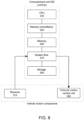
- This aspect concerns a method of steering automated vehicles 20 in a designated area 10. Note, this method and its variants are collectively referred to as the "present methods" in this document. All references S n refer to methods steps of the flowcharts of FIG. 6 , while numeral references pertain to devices, components, and concepts, as involved in embodiments of the present invention.
- the method relies on one or more movable sensors 30 - 34 to update a configuration of a designated area 10 and accordingly plan trajectories for one or more automated vehicles 20, for them to automatically drive to a destination in this area 10.
- the designated area 10 may for instance be an indoor area (e.g., a production plant, a garage, a warehouse) or an outdoor area (e.g., an industrial parking lot).
- the present methods and systems involve at least one movable sensor 30 - 34 and at least one automated vehicle 20.
- the following description mostly refer to a plurality of movable sensors 30 - 34 and a plurality of automated vehicles 20, as involved in typical applications.
- CCU central control unit
- the movable sensors 30 - 34 are instructed S11 to move across the designated area 10, e.g., so as to reach target locations in this area (i.e., static locations, as assumed in FIG. 1 ) or continually move along predefined paths (as assumed in FIG. 2A ). In both cases, the aim is for the movable sensors 30 - 34 to sense S13 the designated area 10 (or local portions thereof) and generate corresponding detection signals.
- the detection signals generated by the sensors encode information as to the sensed area 10 (or parts thereof).
- the area configuration is some digital representation of the area; this representation does not necessarily require a map of the area.
- this configuration includes an object list with respective positions (e.g., 2D positions) of objects, which include the automated vehicles. Additional objects may possibly be listed, such as movable sensors and pedestrians, if any.
- this configuration may include descriptors of bounding volumes (e.g., bounding boxes, see FIG. 5 ), associated with the object positions, with a view to detecting and preventing collisions, for instance.
- the detection signals are preferably transmitted to the CCU 100 (i.e., a server) for it to accordingly update the area configuration.
- the sensors may locally update this configuration, e.g., in a peer-to-peer manner.
- the configuration is updated collaboratively by the movable sensors 30 - 34 and the CCU 100, based on detection signals obtained by the movable sensors.
- updating the area configuration makes it possible to plan S17 vehicle trajectories 25, 25a, by exploiting information contained in the updated configuration.
- vehicle trajectories 25, 25a extend from current positions (normally static) of the vehicles 20 to destination positions (normally static too) in the designated area 10; the destination positions differ from the current positions of the automated vehicles 20.
- the planned vehicle trajectories 25, 25a are eventually transmitted S18 to respective ones of the automated vehicles 20 for the latter to automatically drive to their destination positions.
- the movable sensors 30 - 34 may sense any object in the area, e.g., vehicles 20, other movable sensors 30- 34, pedestrians, or other obstacles, in the area 10.
- the movable sensors 30 - 34 sense the current positions of the vehicles 20 and provide corresponding information to the CCU.
- the method may attempt to reconcile this information with previously known positions of the vehicles, with a view to updating the area configuration.
- a preferred approach is one where the control unit 100 already stores an object list including a list of the automated vehicles and their current positions, then updates S16 this object list thanks to detection signals received S15 from the sensors, as assumed in FIG. 6 .
- the control unit 100 may for instance instruct the movable sensors 30 - 34 to move across the area 10 to reach given target positions, which can be determined in accordance with a logistics goal and last known positions of the automated vehicles 20.
- the movable sensors 30 - 34 sense the area and generate corresponding detection signals that they transmit to the CCU 100 for it to update the area configuration, as assumed in FIG. 1 .
- the movable sensors 30 - 34 may also sense their immediate environment while moving to their target positions, in order to avoid obstacles.
- the movable sensors are embodied as ground vehicles, which can be (at least partly) autonomous, as in embodiments discussed below.
- the sensors may continually sense the area 10 as they move across it, in a continual manner, as assumed in FIGS. 2A - 2C .
- control unit and/or the movable sensors 30 - 34 process the detection signals generated by the sensors 30 - 34 to derive precise positions of vehicles 20 and other objects, if any, so that suitable trajectories may eventually be determined (e.g., in accordance with a logistics goal) and transmitted to the vehicles 20 for them to reach their new positions.
- both the current and destination positions of the vehicles 20 are normally fixed (i.e., static) positions.
- Updating the area configuration amounts to updating the current positions of sensed objects, something that may involve (but does not necessarily require) a cartographic representation (i.e., a map) of the designated area 10.
- the configuration update may, in principle, be done by the movable sensors 30 - 34 and/or processing means of the CCU 100. Still, the CCU 100 is in a better position to reconcile partial information obtained from the sensors 30- 34.
- the area configuration update is preferably managed entirely by the CCU 100 based on the detection signals received from the movable sensors.
- autonomous refers to concepts that involves some self-governance of machines, whereby such machines are capable of sensing their environment to safely move therein, avoiding obstacles and collisions with other objects, whether static or in motion.
- autonomous refers to concepts that involves some self-governance of machines, whereby such machines are capable of sensing their environment to safely move therein, avoiding obstacles and collisions with other objects, whether static or in motion.
- autonomous is to be understood in a broad sense.
- an autonomous device is a device that is automated, and therefore at least partly autonomous, though not necessarily fully autonomous. That is, this device incorporates automation to move (e.g., drive) across the area 10, through typically with external inputs (e.g., from the CCU 100).
- the automated vehicles 20 benefit from some automation, such that they can automatically drive from one location to another, without necessarily being autonomous, i.e., without necessarily being capable of sensing their environments and without necessarily being aware of their locations.
- the automated system of such vehicle is capable of taking full control of the vehicle for the latter to start, accelerate, brake, steer, and stop, so as to be able to move from one location to another.
- the automated vehicles 20 are ground vehicles, typically autonomous cars, which can have various levels of autonomy. In principle, such vehicles 20 can be of any type, e.g., cars, vans, transit buses, motorcoaches, trucks, lorries, or any other types of ground vehicles that may benefit from automation.
- the automated vehicles are production cars, vans, electric vehicles, or the likes, which benefit from automatic driving and are at least level 2 (hands off), possibly level 3 (eyes off), level 4 (mind off), or level 5 (steering wheel optional), according to the system developed by SAE International (formerly named the Society of Automotive Engineers).
- the movable sensors 30 - 34 are unmanned devices that preferably are at least partly autonomous. They can be designed as ground vehicles, aerial vehicles (drones), or devices suspended on a continuous moving cable (like cable cars), for example. In particular, they may be embodied as ground vehicles that are automated to drive along predefined pathways, using artificial aid, e.g., magnetic, or coloured strips. Preferably, though, they are designed as ground vehicles 30 - 34 that are at least partly autonomous, so as to avoid potential collisions with other objects, as assumed in FIGS. 3A-3C . So, motion planning can be used to steer the sensor robots too.
- the movable sensors 30 - 34 are location-aware devices (e.g., having GPS capability), which are more preferably equipped with a Lidar system 36, 37, or a similar system (i.e., based on 3D laser scanning), to allow the vehicles 20 and other objects to be mapped S16 on the designated area.
- the mapping data can be reconciled by the CCU 100. The goal is to determine accurate positions of such objects (including the current positions of the vehicles 20, if necessary), prior to determining the vehicle trajectories 25, 25a.
- Such trajectories 25, 25a typically aim at solving a logistic problem.
- the CCU 100 may have to solve S5 an optimization problem, prior to determining the vehicle trajectories.
- the determined vehicle trajectories 25, 25a are time-dependent motions, as opposed to mere motion paths. I.e., in the present context, trajectories consist of motion paths, augmented with timestamps (or relative time durations), whereby each vehicle 20 is instructed to drive along a certain path with a certain speed (which can vary along the path), starting at a certain time.
- the motions of the vehicles may have to be orchestrated, especially in applications where the vehicles are agnostic to their environments and can therefore not autonomously avoid obstacles and collisions.
- the sensor robots 30 - 34 may have a higher level of autonomy. I.e., the sensor robots may be capable of avoiding obstacles, unlike the vehicles 20. Preferred implementations of such robots are discussed later in detail in respect of another aspect of the invention.
- the proposed solution makes it possible to automatically relocate vehicles 20 in a designated area 10, such as a parking lot of a car production plant. Such areas can be large and accommodate hundreds to thousands of vehicles.
- the vehicles 20 need continually be relocated (e.g., to continually load trucks), which requires fleet logistic optimization.
- the logistics of relocation of vehicles within industrial parking lots is a complex problem.
- One possible way to solve this problem is to rely on static sensors. This, however, requires a large number of sensors, substantial bandwidth, throughputs, and processing power. Plus, static locations may be suboptimal.
- relying on movable sensors reduces the number of required sensors and allows the sensor positions to be finely tuned in accordance with the logistic problem to be solved.
- the robots are preferably designed as ground vehicles 20, as assumed in FIGS. 3A - 3C , and 4 .
- the robots Upon being instructed S11 to drive S12 along respective paths, the robots come to sense S13 the designated area 10 (i.e., at least the parts of the area corresponding to the environments of the robots) and generate corresponding detection signals, whether at the end of the path (i.e., once having reached target positions) and/or along their respective paths.
- the robots 30 - 34 may, in embodiments, only benefit from automatic driving capability, e.g., relying on artificial aids, such as coloured or magnetic strips. In that case, there is no need to plan trajectories for the robots; they just need be instructed to move along their respective paths.
- the sensor robots do not rely on external aid. Still, they may well have limited computational capability and a rather limited level of self-governance. Therefore, their trajectories are preferably precomputed by and transmitted from the CCU 100.
- the robots 30 - 34 are sufficiently autonomous to determine their trajectories themselves, yet based on paths precomputed and transmitted by the CCU 100. Optimal input paths may be provided to the robots based on the last known locations of the vehicles 20 in the designated area 10. To that aim, the robots 30 - 34 are preferably equipped with radio receivers, as in embodiments described later.
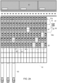
- the designated area 10 consist of a parking lot, which includes 144 parking places, partly occupied by cars 20 that have been recently assembled in the nearby production plant 40.
- the objective in this example is quite simple: a passenger car 20a must be brought closer to the other vehicles, to free up space in the southern part of the parking lot.
- This logistics goal has been devised S5 by a CCU 100 (not shown in FIG. 1 ), based on last known positions of the automated vehicles 20. Having set this logistics goal, the CCU 100 determines S10 optimal target positions for the sensor robots, as well as paths (or trajectories) for the sensor robots 30 - 34 to reach such target positions.
- the sensor robots 30 - 34 are then instructed S11 to drive S12 from their current locations along the transmitted paths to reach their respective target positions. Having reached such target positions, the robots start sensing S13 their respective environments, corresponding to respective parts of the designated area 10, see also FIG. 5 . This causes the robots to generate detection signals, which they transmit S15 to the CCU 100. This, in turn, allows the CCU 100 to update S16 the area configuration. Based on the updated configuration, the CCU 100 determines S17 an optimal trajectory 25 for the outcast vehicle 20a and transmits S18 this trajectory to the vehicle 20a, for the latter to reach its destination position. Although blind and unaware of its environment, the vehicle 20a can drive along the path corresponding to the transmitted trajectory, and in accordance with timing information contained in this trajectory, e.g., thanks to the drive-by-wire system 360 of the vehicle 20.
- the robots sense the area 10 at fixed positions (the target positions).
- the area configuration can be repeatedly updated, thanks to detection signals continually generated by the sensor robots 30 - 34 (still in their target positions) as the automated vehicle 20a automatically drives its destination position.
- the CCU 100 makes it possible for the CCU 100 to continually check for potential collisions. That is, the movable sensors continually sense the area 10 as the vehicle 20a moves, to make sure that no obstacle (starting with pedestrians) interferes with the vehicle 20a. In the unlikely event that an obstacle is detected, which would lead to a collision, a new trajectory (e.g., an emergency stop) can be quickly computed and transmitted by the CCU 100 to the vehicle 20a.
- a new trajectory e.g., an emergency stop
- FIGS. 2A - 2C illustrates a different scenario, where several vehicles 20 are to be relocated closer to a loading area, in the southern region of the parking lot.
- the goal is to be able to load car carrier trailers 50 more efficiently with selected vehicles 20.
- this logistics goal can be initially devised in accordance with the last known positions of the vehicles concerned.
- This example assumes that fewer robots (namely two) 31, 32 are available.
- the robots 31, 32 are instructed to drive along respective paths 3 1p, 32p, starting from their respective charging stations 41, 42 (the robots are assumed to be electrical vehicles), for the robots to sense S13 the designated area 10 while driving along their respective paths 31p, 32p.
- the robots sense their environments along their paths, to repeatedly generate detection signals that are transmitted to the CCU 100 (not shown in FIGS. 2A - 2C ). They may further keep on sensing the area 10 once having reached their target positions, if any, and/or while returning to their charging stations 41, 42, if necessary.
- the detection signals are processed by the CCU 100, which reconciles the partial information encoded in such signals to update the area configuration.
- the CCU 100 can determine optimal trajectories 25a (see FIG. B), in accordance with the logistics goal, and transmit such trajectories to the vehicles 20.
- the latter may then drive in accordance with the transmitted trajectories to reach their destination positions, see FIG. 2C . Not only this makes it possible to bring the cars 20 closer to the trucks 50 but, in addition, this frees up some place in the northern region of the parking lot, with a view to parking newly manufactured vehicles coming from the production site 40, if necessary.
- the paths 31p, 32p can initially be optimized according to some logistics goal, itself devised based on last known positions of the automated vehicles 20, prior to being transmitted to the sensor robots 30 - 34.
- the CCU 100 may determine trajectories instead of mere paths 31p, 32p, should the robots 31, 32 not be sufficiently autonomous. It is anyway advantageous to precompute such trajectories at the CCU, to spare the robots the computational effort.
- the CCU 100 merely transmits optimal paths to the robots 31, 32, which determine S12 their respective trajectories themselves, in accordance with the optimal paths, and then start driving S12 according to the trajectories determined.
- the robots 30 - 34 may be sufficiently autonomous to detect obstacles and stop, if necessary.
- the robots 30 - 34 can be designed to sufficiently autonomous to avoid obstacles and collisions with objects (whether vehicles 20, other robots, or other things), along their paths. I.e., the robots drive at least partly autonomously along paths (or in accordance with trajectories) as initially planned by the CCU 100 or the robots themselves, and may possibly stop or, even, locally deviate from the initial paths (or trajectories) to avoid obstacles.
- the area configuration is preferably updated based on features identified thanks to the detection signals obtained by the robots 30- 34. That is, the present methods may further identify S13, S16 features 24, 24a, which notably include vehicle features 24 of the automated vehicles 20, based on the detection signals generated by the robots.
- the area configuration is accordingly updated based on the identified features. I.e., the current positions of the automated vehicles and other objects, if any, are updated and mapped S16 on the designated area 10, based on the features 24 identified.
- the feature identification can be performed at the robots or the CCU 100. Still, as noted earlier, the configuration update is preferably performed by the CCU 100, based on detection signals obtained from the robots 30 - 34, it being reminded that this unit 100 may have to reconcile partial information obtained from the robots. With this in mind, and given the computational resources that are typically required to perform feature identification, this task is preferably performed by the CCU 100, based on detection signals transmitted by the sensor robots 30 - 34. In less preferred variants, the robots 20 - 34 may locally perform the feature identification and transmit corresponding signals to the CCU.
- the sensor robots may update a partial area configuration, based on the locally sensed environments, and the resulting local configurations may subsequently be transmitted to and reconciled by the CCU 100.
- Such tasks requires substantial computing power at the sensing robots, hence the advantage of performing these tasks at the CCU.
- the present methods may advantageously seek to identify underside features 24 of the vehicles 20, i.e., features corresponding to underbodies of the automated vehicles 20, starting with wheels of the vehicles, as such features are fairly easy to infer using standard cognitive models in computer vision.
- Various techniques known in the field of self-driving cars can usefully be applied in the present context, albeit in respect of detection signals generated by sensing robots instead of autonomous cars. This way, the positions of the automated vehicles 20 may be accurately determined based on the determined positions of the underside features identified S13.
- Robot paths (or trajectories)
- the sensor robots 30 - 34 are preferably designed so as to have a form factor allowing them to pass under frames of the automated vehicles 20. I.e., the robots 30 - 34 are dimensioned so as to be able to pass under the underbody of the vehicles 20. As a result, the paths 3 1p, 32p can be optimized so as to go under the frames of the automated vehicles 20, if necessary. Thus, upon being instructed S11 to move along their paths, the sensor robots 30 - 34 may drive S12 under the vehicle frames, if necessary. Note, this makes it easier to detect features related to wheels, such that the vehicle positions can be determined more accurately.
- the robots 30 - 34 may also be dimensioned so as to be able to drive S12 between vehicles 20 as parked in parallel parking places, at least if the vehicles are parked according to nominal (i.e., acceptable) parking positions.
- both the destination positions and the current positions of the automated vehicles 20 correspond to respective parking places of a parking lot. More generally, though, the initial and/or destination positions may possibly be outside the parking lot, e.g., in a separate loading area or an indoor area. Indoor areas may rely on a mesh of cable car-like devices, in which sensors are suspended on a continuous moving cable.
- More sophisticated relocation logistics may be contemplated, where several vehicles may have to be concomitantly relocated, which requires orchestrating the vehicle trajectories.
- the CCU 100 may first determine motion paths for the automated vehicles 20 to reach their destination positions and then orchestrate motions of the vehicle along the determined motion paths to obtain the vehicle trajectories 25, 25a. This requires another optimization, typically performed by the CCU 100. This will be useful where the vehicles 20 are not sufficiently self-aware of their environment. The same may actually be done for the robots 30 - 34, if necessary. However, the predetermined paths will likely be collision-free. Plus, the sensor robots can be made sufficiently autonomous to prevent collisions.
- the CCU 100 may seek to orchestrate the vehicle motions for the resulting vehicle trajectories 25, 25a to be at least partly concomitant. This effectively decreases the relocation time durations and contributes to improve the overall logistics.
- the vehicle trajectories 25, 25a are planned for time periods during which the sensor robots are static.
- the vehicle trajectories 25, 25a are planned so that the vehicles 20 start driving to their new positions only after all of the robots 30 - 34 have reached their target positions and sensed their environments. This makes it possible to fully decouple motions of the robots 30 - 34 and the vehicles 20, and makes it easier to obtain collision-free trajectories 25, 25a for the vehicles 20, it being reminded that such vehicles may have no collision-avoidance capability.
- the sensor robots 30- 34 may further sense the area 10 as the vehicles start moving, in order to check for potential collisions, as assumed in the scenario of FIG. 1 .
- the area configuration is repeatedly updated (e.g., continually updated), based on detection signals that are repeatedly generated by the sensor robots 30 - 34 as the automated vehicles 20 drive to their destination positions.
- This allows the CCU 100 to continually check for potential collisions based on the continually updated configuration.
- the movable sensors continually scan the area as the vehicles move, to make sure that no obstacle interferes with the vehicles starting with pedestrians. In the unlikely event that an obstacle is detected, which would lead to a collision, a new trajectory e.g., an emergency stop can be transmitted to the vehicle 20 concerned.
- Steps S5, S10, S11, S16 - S18, and S20, are performed by the CCU 100, while steps S12 - S15 are performed by the sensor robots.
- Step S19 is performed by the vehicles 20.
- the CCU analyses a logistics goal (possibly instructed by a human operator) in accordance with the last known positions of the vehicles 20.
- the CCU optimizes paths (or trajectories) for the robots, based on the last known positions of the vehicles, and in accordance with the logistics goal.
- step S11 the CCU transmits the optimized paths (or trajectories) to robots and instructs them to start sensing the area 10. Note, this last instruction may be implicit.
- Step S12 is optional; it concerns cases where mere motion paths are transmitted to the robots.
- the sensor robots determine their initial trajectories, upon receiving their respective paths.
- the robots start driving along their respective paths at step S13, in accordance with the determined trajectories. They continually sense their environment to detect and advert potential collisions, while driving along their paths. Having reached S14 their target positions, the robots 30 - 34 may again sense their environment and accordingly generate detection signals that are transmitted S15 to the CCU for processing, as in the scenario illustrated in FIG. 1 .
- the CCU reconciles S16 information captured in the various detection signals received to update the area configuration.
- the robots may continually generate detection signals along their paths and send such signals to the CCU for processing S16, as described earlier in reference to FIGS. 2A - 2C .
- the CCU determines optimal vehicle trajectories, based on the logistics goal and the area configuration as updated last. Such trajectories are next transmitted S19 to the vehicles 20 for them to relocate S20 to their destination positions. Meanwhile, the robots keep on sensing S14 the area (i.e., the flow loops back to step S14), to continually generate detection signals and send S15 such signals to the CCU, which accordingly update S16 the area configuration. Having updated the area configuration anew, the CCU checks whether the vehicles 20 have reached their destination positions. If so, the CCU stores S20 the final vehicle positions. Else, the CCU updates S17 the vehicle trajectories, if necessary, to improve them or prevent collisions, and then transmit S18 the updated trajectories to the vehicles for them to accordingly modify S19 their current trajectories.
- the system 1 basically includes movable sensors 30 - 34 and a CCU 100, which typically includes one or more computerized units such as illustrated in FIG. 7 .
- the CCU 100 is configured to instruct S11 to move one or more movable sensors 30 - 34 across the designated area 10 for the movable sensors to sense S13 at least a part of the designated area and generate corresponding detection signals. This, in turn, allows the CCU to update the configuration of the designated area 10, based on the generated detection signals.
- the CCU is further configured to plan S17 one or more vehicle trajectories 25, 25a (i.e., from current positions to destination positions in the designated area 10), based on the updated configuration. Accordingly, the CCU can eventually instruct to transmit S18 the vehicle trajectories 25, 25a as planned to respective ones of the automated vehicles 20, so that the latter may automatically drive to their destination positions.
- the trajectories are wirelessly transmitted, using an antenna 112 (see FIG. 4 ), meaning that the vehicles are equipped with a radio receiver.
- the CCU 100 may receive S15 feedback from the sensors 30 - 34 as the vehicles 20 move S19.
- the CCU may possibly receive feedback from the vehicles 20 too, although the latter are preferably agnostic to their environments in typical applications. I.e., the automated vehicles 20 have limited autonomy.
- the movable sensors 30 - 34 are preferably embodied as robots designed as ground vehicles 20, which are at least partly autonomous, as assumed in FIGS. 3A - 3C .
- the sensor robots 30 - 34 are accordingly configured to drive along respective paths across the designated area 10.
- the robots may possibly be configured to determine and re-compute their respective trajectories, in accordance with paths communicated from the CCU 100. Preferably, however, such trajectories are precomputed at the CCU 100.
- the robots may be sufficiently autonomous to avoid obstacles. In case an obstacle is detected, the robots 30 - 34 may for instance stop and transmit their current position, based on which the CCU 100 determines new trajectories for the robots to avoid the obstacles.
- the robots may sense S13 the designated area 10 by continuously sensing their environments, with a view to identifying features (including vehicle features 24), to allow the current positions of the automated vehicles 20 to be updated. More generally, any identified object features may be used to update trajectories of both the robots and the vehicles, if necessary.
- FIG. 5 shows a bounding box 24a corresponding to a detected pedestrian, in addition to bounding boxes 24 corresponding to detected cars.
- the sensor robots 30 - 34 preferably have a form factor, which allows them to go under frames of the automated vehicles 20.
- the CCU 100 may optimize the motion paths 31p, 32p and possibly determine them as paths going under one or more vehicle frames.
- this form factor may further allow the sensor robots to pass between the vehicles, at least if the latter are parked according to nominal positions in the parking places.
- the maximal lateral dimension of each sensor robot 30 - 34 is preferably between 200 mm and 500 mm.
- the maximal vertical dimension shall preferably be between 60 and 150 mm.
- the width of the depicted robot 30 is equal to 295 mm, its length is equal to 410 mm, and its height is 120 mm.
- the robots 30 - 34 can advantageously be designed as holonomic drive systems. I.e., the robots 30 - 34 can be equipped with omnidirectional wheels 34.
- the wheels 34 may for instance be so-called omni wheels or Mecanum wheels. This way, the robots can move laterally without requiring conventional steering, which is handy when manoeuvring in narrow and/or shallow places, for example between vehicles or under vehicle frames.
- the robots are preferably electrical vehicles, which includes one or more batteries.
- the sensor robot 30 has a chassis supporting four independent batteries 33, four electrical motors 34m powered by respective batteries 33, four omnidirectional wheels 34 coupled to respective electrical motors 34m.
- the robot 30 is further equipped with a Lidar sensor 36, mounted on top of the chassis. It also includes a GPS antenna 39, as well as a radio antenna 35.
- the robot further comprises processing means 37, 38, which include a main processing unit 38 (including a GPS processing unit) and a Lidar processing unit 37, the latter connected to the Lidar sensor 36.
- the GPS processing unit is connected to the GPS antenna.
- a radio receiver (not visible) is connected to the antenna 35 for wireless data communication with the CCU 100. The radio receiver is connected to the main processing unit.
- the robots 30 - 34 can be equipped with radio receivers, such that the CCU 100 may instruct to move the robots by radio transmitting predetermined paths or trajectories, as explained earlier.
- the Lidar sensors are used by the robots 30 - 34 to perform a 2D or 3D mapping of the area, i.e., to map surrounding features 24, 24a. Note, in the present context, it is normally sufficient to determine 2D positions of the identified objects.
- Radio communications may be based on a wireless LAN (WLAN) standard or a long-term evolution (LTE) standard, the latter being better suited for large outdoor areas.
- WLAN wireless LAN
- LTE long-term evolution
- the robots With the GPS antenna 39 and the GPS processing unit, the robots have the possibility to localize themselves in the area 10, as well as the vehicles 20 and other objects, assuming the corresponding features are at the robots.
- the robots may for instance implement a differential GPS, to increase the accuracy of the calculated object positions.
- the robots are preferably embodied as battery-powered vehicles, they have to be recharged from times to times, hence the need to orchestrate rotations of active robots.
- the Lidar system 36, 37 of a robot 30 - 34 can be used to scan S13, S14 the underside of the chassis, including wheels, of any other suitable vehicle feature, to make it possible to precisely determine the positions of the vehicles 20. Additional features of the sensor robots are discussed in Sect. 2.3.
- the invention is embodied as a computer program product for steering automated vehicles 20 in a designated area 10.
- the computer program product comprises a computer readable storage medium having program instructions embodied therewith.
- the program instructions are executable by one or more computerized units to cause such computerized units to perform steps as described earlier in reference to the present methods. Note, such instructions may possibly be performed at the CCU 100 only, jointly at the CCU 100 and the robot(s) 30 - 34, or at the robot(s) 30 - 34 only, e.g., in a peer-to-peer manner. Additional features of the computer program products are discussed in Sect. 3.
- the method steps S5, S10, S11, S16 - S18, and S20, described earlier in reference to FIG. 6 are implemented in software, e.g., as one or more executable programs, executed by processing means of the CCU 100, which may include one or more computerized units. Any such computerized unit may generally have the architecture 100 shown in FIG. 7 .
- the computerized system 100 involves one or more processors 105 and a memory 110 (meant to act as a main memory), coupled to a memory controller 115.
- the processors 105 are hardware devices for executing software, as loaded in the main memory of the system 100.
- the processors can be any custom made or commercially available processors; they may possibly include graphics processing units (GPUs), which can be leveraged to perform machine learning inferences, notably for computer vision-related tasks.
- GPUs graphics processing units
- the memory 110 may include a combination of volatile memory elements (e.g., random access memory) and non-volatile memory elements, e.g., solid-state devices.
- the software in memory may include one or more separate programs, each of which may for instance comprise an ordered listing of executable instructions for implementing logical functions.
- the software loaded in the memory 110 includes methods described herein in accordance with exemplary embodiments and a suitable operating system (OS).
- the OS essentially controls the execution of other computer (application) programs and provides scheduling, I/O control, file, data and memory management, and communication control as well as related services.
- the system 100 further include one or more input and/or output (I/O) devices 145, 150, 155 (or peripherals) communicatively coupled via a local input/output controller 135.
- the I/O devices notably includes an antenna 112, to communicate with the sensors 30 - 34 and vehicles 20.
- the input/output controller 135 can comprise or connect to one or more buses 140 or other wired or wireless connections.
- the I/O controller 135 may have additional elements, which are omitted for simplicity, such as controllers, buffers (caches), drivers, and receivers, etc., to enable communications.
- a local interface may include address, control, and/or data connections to enable appropriate communications among the aforementioned components.
- I/O devices 145 - 155 may include other hardware devices, which communicate both inputs and outputs.
- the system 100 may further include a display controller 125 coupled to a display 130.
- the system 100 may further include a network interface 160 or transceiver for coupling to a network (not shown).
- the methods described herein shall typically be, at least partly, in the form of executable program, script, or, more generally, executable instructions.
- one or more of the processing elements 105 execute software stored within the memory 110 (separate memory elements may possibly be dedicated to each processing element), to communicate data to and from the memory 110, and to generally control operations pursuant to software instructions.
- the methods described herein, in whole or in part are read by one or more of the processing elements 105, typically buffered therein, and then executed.
- the methods described herein are implemented in software, the methods can be stored on any computer readable medium for use by or in connection with any computer related system or method.
- Computer readable program instructions described herein can be downloaded to processing elements 105 from a computer readable storage medium, via a network, for example, the Internet and/or a wireless network.
- a network adapter card or network interface 160 in the device may receive the computer readable program instructions from the network and forwards the program instructions for storage in a computer readable storage medium 120 interfaced with the processing elements.
- a computer program product may include a computer readable storage medium (or media) having computer readable program instructions thereon for causing a processor to carry out aspects of the present invention.
- the computer readable storage medium can be a tangible device that can retain and store instructions for use by an instruction execution device.
- the computer readable storage medium may for example be an electronic storage device, a magnetic storage device, an optical or electromagnetic storage device, a semiconductor storage device, or any suitable combination of the foregoing. Examples of such storage media include: a hard disk, a random-access memory (RAM), a static random-access memory (SRAM), an erasable programmable read-only memory (EPROM or Flash memory), a memory stick, and any suitable combination of the foregoing.
- a computer readable storage medium is not to be construed as being transitory signals per se, such as radio waves or other freely propagating electromagnetic waves, electromagnetic waves propagating through a waveguide or other transmission media (e.g., light pulses passing through a fibre-optic cable), or electrical signals transmitted through a wire.
- FIG. 8 is a functional diagram showing computerized components of a vehicle 20, wherein such components interact to perform step 19 as described earlier in reference to FIG. 6 .
- the vehicle 20 comprises a computerized unit 200, which interacts with vehicle motion components, which notably includes a radio receiver 310.
- vehicle motion components which notably includes a radio receiver 310.
- the vehicle 20 may optionally include sensors, should the vehicle be configured as an autonomous vehicle. This, however, is typically not the case in the present context.
- the architecture of the computerized unit 200 is similar to that of the CCU 100. It includes a processor 230 and a memory 250 coupled to one or memory controllers 240.
- the processor 230 is a hardware device for executing software, as e.g., loaded in a main memory 250 of the unit 200.
- the processor 230 is typically a central processing unit (CPU), i.e., a custom made or commercially available processor.
- the unit further includes storage means 255, notably storing methods in the form of software, meant to be loaded in the memory 250 and executed by the CPU.
- the system bus 270 transmits data throughout the computer unit 200, from and to the connected devices, e.g., the radio receiver 310, which wirelessly receives data from the CCU 100 (via the antenna 112), and the vehicle motion control unit 360, which includes a drive by wire (DbW) system.
- the computerized unit 200 instructs the control unit 360 to operate the vehicle 20 in a partly autonomous or automated manner, based on signals produced in accordance with instructions received via the receiver 310.
- Steps S12 - S15 are performed by the sensor robots.
- the computer architecture 300 of the sensor robots 30 - 34 include processing means 305, memory 320, and one or more memory controllers 310.
- the system bus 330 coordinate data flows throughout the robot components described earlier in reference to FIGS. 3A - 3C , i.e., the four electrical motors 34m (via a dedicated control unit 360), the Lidar sensor 36 (via the respective processing unit 37), the GPS antenna 39 (via the GPS processing unit 340), and the antenna 35 (via the radio transceiver 370, possibly a mere receiver).
- the computerized unit 300 includes storage means 350, storing methods in the form of software, meant to be loaded in the memory 320 and executed by the main processing unit 305, to operate the sensor robot in accordance with embodiments described in Sect. 1.
- These computer readable program instructions may be provided to one or more processing elements as described above, to produce a machine, such that the instructions, which execute via the one or more processing elements create means for implementing the functions or acts specified in the block or blocks of the flowchart and the block diagram.
- Such program instructions may also be stored in a computer readable storage medium.
- Each computer-implemented block in the flowchart or the block diagram may represent a module, or a portion of instructions, which comprises executable instructions for implementing the functions or acts specified therein.
- the functions or acts mentioned in the blocks may occur out of the order specified in the figures.
- two blocks shown in succession may actually be executed in parallel, concurrently, or still in a reverse order, depending on the functions involved and the algorithm optimization used.
- each block and combinations thereof can also be adequately distributed through special-purpose hardware components.
- the present invention is not limited to the particular embodiments disclosed, but that the present invention will include all embodiments falling within the scope of the appended claims.
- many other variants than explicitly touched above can be contemplated.
- the robots 30 - 34 may have a different design, e.g., based on a different type of wheel.
Landscapes
- Engineering & Computer Science (AREA)
- Aviation & Aerospace Engineering (AREA)
- Radar, Positioning & Navigation (AREA)
- Remote Sensing (AREA)
- Physics & Mathematics (AREA)
- General Physics & Mathematics (AREA)
- Automation & Control Theory (AREA)
- Control Of Position, Course, Altitude, Or Attitude Of Moving Bodies (AREA)
Priority Applications (1)
| Application Number | Priority Date | Filing Date | Title |
|---|---|---|---|
| EP22216503.7A EP4390598B1 (fr) | 2022-12-23 | 2022-12-23 | Gestion de véhicules automatisés dans une zone désignée grâce à des robots terrestres configurés comme capteurs mobiles |
Applications Claiming Priority (1)
| Application Number | Priority Date | Filing Date | Title |
|---|---|---|---|
| EP22216503.7A EP4390598B1 (fr) | 2022-12-23 | 2022-12-23 | Gestion de véhicules automatisés dans une zone désignée grâce à des robots terrestres configurés comme capteurs mobiles |
Publications (3)
| Publication Number | Publication Date |
|---|---|
| EP4390598A1 true EP4390598A1 (fr) | 2024-06-26 |
| EP4390598C0 EP4390598C0 (fr) | 2026-01-07 |
| EP4390598B1 EP4390598B1 (fr) | 2026-01-07 |
Family
ID=84604131
Family Applications (1)
| Application Number | Title | Priority Date | Filing Date |
|---|---|---|---|
| EP22216503.7A Active EP4390598B1 (fr) | 2022-12-23 | 2022-12-23 | Gestion de véhicules automatisés dans une zone désignée grâce à des robots terrestres configurés comme capteurs mobiles |
Country Status (1)
| Country | Link |
|---|---|
| EP (1) | EP4390598B1 (fr) |
Citations (4)
| Publication number | Priority date | Publication date | Assignee | Title |
|---|---|---|---|---|
| US10311731B1 (en) * | 2014-09-16 | 2019-06-04 | Knightscope, Inc. | Autonomous parking monitor |
| EP3657385A2 (fr) * | 2018-11-23 | 2020-05-27 | BlackBerry Limited | Systèmes et procédés de détection de véhicules à l'intérieur d'un parc de stationnement de véhicules |
| US20200272837A1 (en) * | 2019-02-25 | 2020-08-27 | Quantifly Llc | Vehicle Parking Data Collection System and Method |
| US20200334985A1 (en) * | 2019-04-22 | 2020-10-22 | Baidu Usa Llc | Parking management architecture for parking autonomous driving vehicles |
-
2022
- 2022-12-23 EP EP22216503.7A patent/EP4390598B1/fr active Active
Patent Citations (4)
| Publication number | Priority date | Publication date | Assignee | Title |
|---|---|---|---|---|
| US10311731B1 (en) * | 2014-09-16 | 2019-06-04 | Knightscope, Inc. | Autonomous parking monitor |
| EP3657385A2 (fr) * | 2018-11-23 | 2020-05-27 | BlackBerry Limited | Systèmes et procédés de détection de véhicules à l'intérieur d'un parc de stationnement de véhicules |
| US20200272837A1 (en) * | 2019-02-25 | 2020-08-27 | Quantifly Llc | Vehicle Parking Data Collection System and Method |
| US20200334985A1 (en) * | 2019-04-22 | 2020-10-22 | Baidu Usa Llc | Parking management architecture for parking autonomous driving vehicles |
Non-Patent Citations (1)
| Title |
|---|
| SANNGOEN WANAYUTH ET AL: "Parking place inspection system utilizing a mobile robot with a laser range finder", SYSTEM INTEGRATION (SII), 2012 IEEE/SICE INTERNATIONAL SYMPOSIUM ON, IEEE, 16 December 2012 (2012-12-16), pages 55 - 60, XP032323437, ISBN: 978-1-4673-1496-1, DOI: 10.1109/SII.2012.6426967 * |
Also Published As
| Publication number | Publication date |
|---|---|
| EP4390598C0 (fr) | 2026-01-07 |
| EP4390598B1 (fr) | 2026-01-07 |
Similar Documents
| Publication | Publication Date | Title |
|---|---|---|
| US11373395B2 (en) | Methods and systems for simultaneous localization and calibration | |
| EP3612906B1 (fr) | Procédé et système de génération et d'alignement de carte d'environnement | |
| CN104133471B (zh) | 无人驾驶运输车辆及运行方法,包括该无人驾驶运输车辆的系统及规划虚拟轨迹的方法 | |
| US20240419175A1 (en) | Communication systems for self-driving vehicles, and methods of providing thereof | |
| EP4165376B1 (fr) | Procédés et systèmes d'exécution d'une relinéarisation inter-trajectoires autour d'un trajet de référence évolutif pour un véhicule autonome | |
| JP6956192B2 (ja) | ロボットアドホックネットワーク | |
| US11537140B2 (en) | Mobile body, location estimation device, and computer program | |
| US11221632B2 (en) | Method for checking a collision between two driverless transport vehicles, driverless transport vehicle, and system having a plurality of driverless transport vehicles | |
| WO2023147769A1 (fr) | Systèmes, procédés et supports lisibles par ordinateur pour la planification de mouvement spatio-temporelle | |
| US20230022637A1 (en) | Information processing apparatus, information processing method, and program | |
| US12118837B2 (en) | Responding to autonomous vehicle error states | |
| US20250262762A1 (en) | Robot control method and system based on deep reinforcement learning | |
| US20250236317A1 (en) | Autonomous vehicle blind spot management | |
| KR20210059460A (ko) | 물류 자동화를 위한 자율 주행 로봇의 원격 관제 시스템 | |
| EP4102473B1 (fr) | Procédé et dispositif pour faire fonctionner une voiture autonome | |
| EP4390598A1 (fr) | Gestion de véhicules automatisés dans une zone désignée grâce à des robots terrestres configurés comme capteurs mobiles | |
| CN119325584A (zh) | 智能配送车辆及其控制方法 | |
| JP2024022888A (ja) | 地図自動生成装置及び搬送車両システム | |
| Singholi et al. | A review on IoT-based hybrid navigation system for mid-sized autonomous vehicles | |
| US20230351896A1 (en) | Transportation service provision with a vehicle fleet | |
| US12547966B2 (en) | Dynamic purchase interface for real-time middle-mile purchase and delivery | |
| US20250224741A1 (en) | Delivery system and method for middle-mile cargo delivery using unmanned aerial vehicles | |
| CN120897830A (zh) | 用于预测物流机器人碰撞的装置和方法 | |
| CN120333410A (zh) | 用于车辆的定位和导航到充电站的系统和方法 | |
| CN121921990A (zh) | 用于车辆编组的系统和方法 |
Legal Events
| Date | Code | Title | Description |
|---|---|---|---|
| PUAI | Public reference made under article 153(3) epc to a published international application that has entered the european phase |
Free format text: ORIGINAL CODE: 0009012 |
|
| STAA | Information on the status of an ep patent application or granted ep patent |
Free format text: STATUS: THE APPLICATION HAS BEEN PUBLISHED |
|
| AK | Designated contracting states |
Kind code of ref document: A1 Designated state(s): AL AT BE BG CH CY CZ DE DK EE ES FI FR GB GR HR HU IE IS IT LI LT LU LV MC ME MK MT NL NO PL PT RO RS SE SI SK SM TR |
|
| STAA | Information on the status of an ep patent application or granted ep patent |
Free format text: STATUS: REQUEST FOR EXAMINATION WAS MADE |
|
| 17P | Request for examination filed |
Effective date: 20241227 |
|
| STAA | Information on the status of an ep patent application or granted ep patent |
Free format text: STATUS: EXAMINATION IS IN PROGRESS |
|
| 17Q | First examination report despatched |
Effective date: 20250327 |
|
| REG | Reference to a national code |
Ref country code: DE Ref country code: DE Ref legal event code: R079 Ref document number: 602022028349 Country of ref document: DE Free format text: PREVIOUS MAIN CLASS: G05D0001020000 Ipc: G05D0001698000 |
|
| GRAP | Despatch of communication of intention to grant a patent |
Free format text: ORIGINAL CODE: EPIDOSNIGR1 |
|
| STAA | Information on the status of an ep patent application or granted ep patent |
Free format text: STATUS: GRANT OF PATENT IS INTENDED |
|
| RIC1 | Information provided on ipc code assigned before grant |
Ipc: G05D 1/698 20240101AFI20250717BHEP Ipc: G06Q 10/08 20240101ALI20250717BHEP Ipc: G05D 105/80 20240101ALI20250717BHEP Ipc: G05D 107/70 20240101ALI20250717BHEP Ipc: G05D 109/18 20240101ALI20250717BHEP |
|
| INTG | Intention to grant announced |
Effective date: 20250804 |
|
| GRAS | Grant fee paid |
Free format text: ORIGINAL CODE: EPIDOSNIGR3 |
|
| GRAA | (expected) grant |
Free format text: ORIGINAL CODE: 0009210 |
|
| STAA | Information on the status of an ep patent application or granted ep patent |
Free format text: STATUS: THE PATENT HAS BEEN GRANTED |
|
| AK | Designated contracting states |
Kind code of ref document: B1 Designated state(s): AL AT BE BG CH CY CZ DE DK EE ES FI FR GB GR HR HU IE IS IT LI LT LU LV MC ME MK MT NL NO PL PT RO RS SE SI SK SM TR |
|
| REG | Reference to a national code |
Ref country code: CH Ref legal event code: F10 Free format text: ST27 STATUS EVENT CODE: U-0-0-F10-F00 (AS PROVIDED BY THE NATIONAL OFFICE) Effective date: 20260107 Ref country code: GB Ref legal event code: FG4D |
|
| REG | Reference to a national code |
Ref country code: CH Ref legal event code: R17 Free format text: ST27 STATUS EVENT CODE: U-0-0-R10-R17 (AS PROVIDED BY THE NATIONAL OFFICE) Effective date: 20260109 |
|
| REG | Reference to a national code |
Ref country code: DE Ref legal event code: R096 Ref document number: 602022028349 Country of ref document: DE |
|
| REG | Reference to a national code |
Ref country code: IE Ref legal event code: FG4D |
|
| U01 | Request for unitary effect filed |
Effective date: 20260113 |
|
| U07 | Unitary effect registered |
Designated state(s): AT BE BG DE DK EE FI FR IT LT LU LV MT NL PT RO SE SI Effective date: 20260119 |
|
| RAP4 | Party data changed (patent owner data changed or rights of a patent transferred) |
Owner name: EMBOTECH AG |
|
| U1H | Name or address of the proprietor changed after the registration of the unitary effect |
Owner name: EMBOTECH AG; CH |