EP4390888B1 - Verfahren zur branderkennung bei produktionsmaschinen und produktionsmaschine - Google Patents
Verfahren zur branderkennung bei produktionsmaschinen und produktionsmaschine Download PDFInfo
- Publication number
- EP4390888B1 EP4390888B1 EP22216612.6A EP22216612A EP4390888B1 EP 4390888 B1 EP4390888 B1 EP 4390888B1 EP 22216612 A EP22216612 A EP 22216612A EP 4390888 B1 EP4390888 B1 EP 4390888B1
- Authority
- EP
- European Patent Office
- Prior art keywords
- production machine
- production
- process controller
- fire
- machines
- Prior art date
- Legal status (The legal status is an assumption and is not a legal conclusion. Google has not performed a legal analysis and makes no representation as to the accuracy of the status listed.)
- Active
Links
Images


Classifications
-
- G—PHYSICS
- G08—SIGNALLING
- G08B—SIGNALLING SYSTEMS, e.g. PERSONAL CALLING SYSTEMS; ORDER TELEGRAPHS; ALARM SYSTEMS
- G08B17/00—Fire alarms; Alarms responsive to explosion
- G08B17/12—Actuation by presence of radiation or particles, e.g. of infrared radiation or of ions
- G08B17/125—Actuation by presence of radiation or particles, e.g. of infrared radiation or of ions by using a video camera to detect fire or smoke
-
- C—CHEMISTRY; METALLURGY
- C03—GLASS; MINERAL OR SLAG WOOL
- C03B—MANUFACTURE, SHAPING, OR SUPPLEMENTARY PROCESSES
- C03B9/00—Blowing glass; Production of hollow glass articles
- C03B9/30—Details of blowing glass; Use of materials for the moulds
- C03B9/40—Gearing or controlling mechanisms specially adapted for glass-blowing machines
- C03B9/41—Electric or electronic systems
Definitions
- the present invention relates to a method for fire detection in machines for producing hollow glass, wherein a manufacturing process on a production machine is controlled by means of a process control and the production machine is permanently monitored by means for fire detection.
- Another method is from the JP 2021-045723 A
- waste is also processed using a conveyor belt.
- an infrared camera is used to control the conveyor belts accordingly and the waste is separated.
- WO 2019/224122 A1 A fire alarm network with a central control unit and several networked fire alarm systems that include an infrared camera is known.
- the production of hollow glass is to be used here.
- molten glass first flows from a melting tank into a feeder.
- a scissor mechanism is provided under the feeder tank, which shears off individual drops formed there, which are fed to a preform via a drop distributor.
- the glass is pressed into the lower part, the mouth and preform, in a first blowing process.
- a level is formed at the mouth, around which the glass forms a molding.
- compressed air is then introduced to inflate the molding until it forms a thin-walled parison that rests against the inner wall of the preform. This is transported to a finishing mold, where it is further shaped into its final form using compressed air.
- the level is first designed as a kind of stamp by applying pressure, pressed into the preform and the glass is thus pre-formed into a parison, but the final shaping is again carried out using compressed air.
- This type of process is particularly prone to fires, as the hot material can easily cause fires, particularly when it comes into contact with machine oil and grease, which is required for lubrication on the moving parts and molded parts of production machines.
- the additional use of compressed air in the production process and the use of cooling air to control the temperature of production machines can further fuel such fires.
- the problem is that the machine operator has to be on site all the time and even then is not able to oversee the entire area from several levels. Then he must first recognize a fire and assess it as such, and take the necessary steps such as activating the emergency stop. Every system, from the feed to the material transport, cooling and lubrication, especially the production machine itself, to the removal of the products, has its own emergency stop. There is not necessarily a global emergency stop for all associated systems. This does not guarantee that all systems will be switched off safely and without voltage.
- Another problem is the emergency stop itself, which causes the production machine and the conveyor belts to stop abruptly. This means that the production machine is completely under hot, glowing glass and the temperature in and around the machine increases significantly because the cooling system is also switched off, so that a small local oil fire can quickly spread to other areas. In addition, the glowing glass containers in the machine and on the conveyor belt pose a danger to the fire-fighting personnel.
- the present invention is based on the object of specifying a method for fire detection in industrial production machines, as well as such a production machine, which automatically creates a safe state even at high production temperatures before the start of an extinguishing process in order to reduce the risk of a major fire for people and machines.
- a method for fire detection in industrial production machines for the manufacture of hollow glass wherein a production process on a production machine is controlled using a process control system and the production machine is permanently monitored by means for fire detection.
- this is characterized in that in a first step, the means for fire detection generate an alarm signal and transmit it to the process control system, in a second step, the process control system terminates the request for material for the production process and further material is retained in a fire-safe retention device, while the production machine processes or ejects material that has already been inserted and is then stopped, and in a third step, all machines that supply material and remove products are stopped.
- an alarm signal is generated and forwarded to the process control.
- the process control then takes further measures in a second and third step to ensure a safe condition.
- the material requirement for the entire machine is stopped so that no additional material enters the production machine. In the case of glass production, this means that the drop request is terminated and the drop distributor is deactivated and swung out. This prevents further liquid glass from being fed into the production machine and heating it further. Glass held in the melting tank and melting furnace remains there in a fire-safe containment.
- the production machine is emptied in a further step.
- this can mean that the material is ejected and removed, or that the production machine finishes producing the product it has started and then ejects it.
- the individual stations are brought to a controlled station stop. Each station runs for two cycles and then stops.
- the cooling and lubrication can be deactivated, which eliminates the possibility of fire acceleration caused by cooling air and flammable lubricant.
- the finished products can be ejected properly onto conveyor belts that are still running, and are only switched off in a third step along with all supply and discharge systems.
- the system then goes into emergency stop mode, meaning that all control and drive systems in the vicinity of the production machine are safely stopped. In this state, all connected systems are switched off, secured against accidental restart, and de-energized so that fire-fighting can begin.
- the means for fire detection comprise at least one infrared camera which is aimed at the production machine or parts thereof and generates a thermal image, whereby in the event of at least one thermal threshold being exceeded, an alarm signal is transmitted to the process control system.
- the use of such infrared cameras allows for comprehensive monitoring of the area around the production machine, as the entire field of view of an infrared camera is monitored, whereas temperature sensors can only monitor a very specific, limited area.
- the infrared cameras capture a thermal image in which the heat radiation from a point is coded using a corresponding color. Suitable image recognition processes can be used to determine whether a heat threshold is exceeded in the image and, in this case, an alarm can be triggered.
- this can be implemented in such a way that the infrared camera's field of view is divided into areas and one or more areas are assigned their own heat threshold. This makes it possible to define areas that can reach high temperatures without triggering an alarm, while other areas can be suspected of a fire at significantly lower temperatures and trigger an alarm.
- the infrared cameras are assigned air nozzles in the area of their camera lenses, which create an air shield to protect the camera lenses from dirt.
- Such an air shield can keep dirt away from the camera lenses, while the imaging radiation can still hit the camera lens.
- purely manual means for fire detection can also be provided, such as push buttons. If the staff detects a fire at an early stage or if it occurs outside the field of view of all infrared cameras, an alarm signal can also be sent manually to the process control system in this way.
- the push button is particularly advantageous in that it also has an acknowledgement switch with which the alarm can be turned off again. The measures according to the invention that have been started are then ended again. In a specific embodiment, only the manual alarm can be acknowledged in this way.
- a fourth step at least one extinguishing device is switched on to wet the surfaces of the production machine with an extinguishing agent.
- This can be achieved specifically by means of sprinklers, which can be arranged in the area of the production machine and in other places where there is a risk of fire.
- the process control system triggers a visual and/or acoustic alarm by activating signaling devices in response to the first step.
- a visual and/or acoustic alarm signals the personnel in the area of the production machine that a fire has been detected and that appropriate measures must be taken.
- the alarm is signaled to the personnel via suitable signaling devices, be it acoustic or optical signaling devices, but also electronic messages on smart devices, which in turn can emit haptic signals.
- suitable signaling devices be it acoustic or optical signaling devices, but also electronic messages on smart devices, which in turn can emit haptic signals.
- the personnel can then ensure that people and machines are brought into a safe state and that the fire can then be fought.
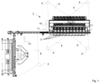
- Figure 1 shows a production machine 1 with additional devices and machines in a top view. It is a production machine 1 for producing hollow glass, i.e. glass bottles, glass containers such as jars and the like.
- the production machine 1 is an IS machine, which therefore has individual sections 2 in which products 9, namely glass bottles, are produced in parallel. Since the production machine 1 works with liquid glass, which has a temperature of around 1100 °C after melting and is processed at such a temperature, and also has to be lubricated in order to ensure its function with moving parts, the fire risk in the production machine 1 must be considered significant.
- several distributed infrared cameras 5 are assigned to the production machine 1 as a means of fire detection, which cover the individual sections 2 of the production machine 1 and at least observe common sources of fire.
- the fields of view 6 of the infrared cameras 5 are aligned in such a way that production is monitored, but also general overview areas are covered.
- a fire occurs on the production machine 1, which can be caused by an improperly guided glass drop on the drop distributor, which falls down, is fanned by a cooling air flow or by escaping compressed air from the production process and spreads to other areas, this is detected by at least one infrared camera 5 at an early stage and an alarm signal is transmitted to a process control 10.
- the process control 10 is in the Figure 1 exemplary drawn in the immediate vicinity of the production machine 1, but can be located at a greater distance for safety reasons, as long as the reliable data transmission to the process control 10 is guaranteed.
- buttons 11 are distributed in the field, with the help of which the staff can also signal an alarm, for example if a fire is seen by chance at a very early stage, before the detection thresholds of the infrared cameras 5 are reached or are outside their field of view 6.
- the push buttons 11 are also equipped with acknowledgement switches with which an accidental mechanical triggering of an alarm can be acknowledged and the alarm can be turned off.
- a signal generator 12 causes both a visual alarm via a signal light and an acoustic alarm via a siren as soon as an alarm is triggered, either by the infrared cameras 5 or manually via a push button 11.
- FIG. 2 shows a schematic representation of a thermal image 7 of an infrared camera 5, which is directed into a production area of the production machine 1.
- Products 9 in the form of glass drops or gobs are shown on it, as well as an area 8 that is essential for the function of the infrared camera 5.
- only the area 8 in which a certain threshold value should not be exceeded is monitored. If this threshold value is exceeded outside of the area 8, for example in the droplet fall and swivel area, this area is outside the monitored area 8 and this is permissible for production reasons. However, if the threshold value is exceeded within the area 8, this deviates from the specifications and causes an alarm signal from the relevant infrared camera 5 to the process control 10.
- Figure 3 illustrates the following process.
- the system is in a state of permanent monitoring 14.
- the question that arises throughout is 15 whether the threshold value in one of the Thermal images 7, as in Figure 2 shown is exceeded. As long as this is not the case, monitoring 14 will continue.
- the first step 16 of the system's reaction begins.
- an alarm signal 17 is transmitted, initially and primarily to the process control 10. In parallel, this can also be done directly to the signal generator 12, or alternatively, the alarm signal can also be forwarded via the process control.
- the second step 18 follows practically immediately after the first step 16. It is optionally possible to wait for a grace period in order to keep the option open of switching back from the alarm situation to permanent monitoring via an acknowledgement 4. This is possible at any time, whereby the acknowledgement 4 can be carried out via the process control 10 or manually via acknowledgement switches on the push buttons 11.
- the process control system 10 takes initial measures, which do not, however, involve immediately shutting down the machines or even taking extinguishing measures, but are intended to create a safe state first.
- the request for material from the drop distributor 3 is terminated, which also includes terminating cooling and lubrication in order to remove the basis for the fire.
- the processing of material is then initiated by the production machine 1, which processes the material used by continuing to work for two production cycles and ultimately ejects the products 9 that are still being manufactured in an orderly manner. These are then transported away by the system's transport means, for example via a conveyor belt, and fed towards the cooling track.
- a third step 22 follows in which, in a sub-step 23, the supply and discharge Machines are stopped and de-energized. This ensures that extinguishing agents such as water can now be used without creating dangers due to electrical voltage.
- a fourth step 24 can now follow in which extinguishing devices 13, such as sprinklers and the like, are put into operation and the fire is fought.
Landscapes
- Engineering & Computer Science (AREA)
- Multimedia (AREA)
- Business, Economics & Management (AREA)
- Emergency Management (AREA)
- Physics & Mathematics (AREA)
- General Physics & Mathematics (AREA)
- Fire-Detection Mechanisms (AREA)
Priority Applications (3)
| Application Number | Priority Date | Filing Date | Title |
|---|---|---|---|
| EP22216612.6A EP4390888B1 (de) | 2022-12-23 | 2022-12-23 | Verfahren zur branderkennung bei produktionsmaschinen und produktionsmaschine |
| ES22216612T ES3023838T3 (en) | 2022-12-23 | 2022-12-23 | Method for detecting fires in production machines and production machine |
| PL22216612.6T PL4390888T3 (pl) | 2022-12-23 | 2022-12-23 | Sposób wykrywania pożarów w maszynach produkcyjnych i maszyna produkcyjna |
Applications Claiming Priority (1)
| Application Number | Priority Date | Filing Date | Title |
|---|---|---|---|
| EP22216612.6A EP4390888B1 (de) | 2022-12-23 | 2022-12-23 | Verfahren zur branderkennung bei produktionsmaschinen und produktionsmaschine |
Publications (3)
| Publication Number | Publication Date |
|---|---|
| EP4390888A1 EP4390888A1 (de) | 2024-06-26 |
| EP4390888B1 true EP4390888B1 (de) | 2025-01-29 |
| EP4390888C0 EP4390888C0 (de) | 2025-01-29 |
Family
ID=84602404
Family Applications (1)
| Application Number | Title | Priority Date | Filing Date |
|---|---|---|---|
| EP22216612.6A Active EP4390888B1 (de) | 2022-12-23 | 2022-12-23 | Verfahren zur branderkennung bei produktionsmaschinen und produktionsmaschine |
Country Status (3)
| Country | Link |
|---|---|
| EP (1) | EP4390888B1 (pl) |
| ES (1) | ES3023838T3 (pl) |
| PL (1) | PL4390888T3 (pl) |
Family Cites Families (9)
| Publication number | Priority date | Publication date | Assignee | Title |
|---|---|---|---|---|
| CH687653A5 (de) | 1994-03-17 | 1997-01-15 | Von Roll Umwelttechnik Ag | Brandueberwachungssystem. |
| DE19722921A1 (de) * | 1997-05-31 | 1998-12-03 | Schott Zwiesel Glaswerke | Verfahren zur Herstellung von Hohlglas-Formkörpern und zugehörige Vorrichtung zur Durchführung des Verfahrens |
| CN102176270A (zh) | 2011-02-25 | 2011-09-07 | 广州飒特电力红外技术有限公司 | 安全监控及火灾预警一体化系统及方法 |
| DE102012104625B4 (de) * | 2012-05-29 | 2017-04-27 | Waltec Maschinen Gmbh | Vorrichtung zur Herstellung von Hohlkörpern aus einer Glasschmelze |
| WO2014169066A1 (en) | 2013-04-09 | 2014-10-16 | Thermal Imaging Radar, LLC | Fire detection system |
| KR101663489B1 (ko) * | 2014-12-04 | 2016-10-07 | (주)티티에스 | 열화상 감지 센서를 이용한 반도체 또는 디스플레이 제조설비의 화재 모니터링 장치 |
| GB2574010A (en) | 2018-05-21 | 2019-11-27 | Tyco Fire & Security Gmbh | Fire alarm verification |
| WO2020148625A1 (en) * | 2019-01-15 | 2020-07-23 | Ase-Advanced Safety Engineering Societa' A Responsabilita' Limitata | Apparatus for detecting symptoms of thermal and/or mechanical anomalies that can lead to the ignition of a fire |
| JP7655696B2 (ja) | 2019-09-19 | 2025-04-02 | 株式会社タクマ | ごみ処理施設の発火検知システム、及び発火検知方法 |
-
2022
- 2022-12-23 EP EP22216612.6A patent/EP4390888B1/de active Active
- 2022-12-23 ES ES22216612T patent/ES3023838T3/es active Active
- 2022-12-23 PL PL22216612.6T patent/PL4390888T3/pl unknown
Also Published As
| Publication number | Publication date |
|---|---|
| ES3023838T3 (en) | 2025-06-03 |
| EP4390888A1 (de) | 2024-06-26 |
| EP4390888C0 (de) | 2025-01-29 |
| PL4390888T3 (pl) | 2025-06-09 |
Similar Documents
| Publication | Publication Date | Title |
|---|---|---|
| EP3052363B1 (de) | Vorrichtung zum automatischen fahren eines fahrzeugs | |
| CN107848869B (zh) | 用于生产中空玻璃产品的方法中的型坯模具的润滑 | |
| DE10033077A1 (de) | Lichtgitter | |
| DE69810982T2 (de) | System zur Bestimmung der Ankunftszeit von Glastropfen bei der Herstellung von Glasrartikeln in einer IS-Maschine | |
| EP3551420A1 (de) | Verfahren und vorrichtung zum visualisieren oder beurteilen eines prozesszustandes | |
| EP1353196A1 (de) | Objekterfassung und Lichtgitter | |
| EP4390888B1 (de) | Verfahren zur branderkennung bei produktionsmaschinen und produktionsmaschine | |
| DE102013209526A1 (de) | Verfahren und Vorrichtung zum Erkennen eines Schnittabrisses | |
| WO2020087101A1 (de) | Verfahren zum betreiben eines maschinensteuerungssystems sowie entsprechendes maschinensteuerungssystem | |
| EP2718135B1 (de) | Verfahren und steuerungssystem zum schnellen und sicheren ansteuern von kraftstoffpumpen | |
| WO2019001948A1 (de) | Schmelzspinnvorrichtung | |
| DE102017119275B4 (de) | Lichtvorhang | |
| EP0040756B1 (de) | Vorrichtung zur Herstellung von Hohlglasartikeln | |
| DE102018221868A1 (de) | Vorrichtung und Verfahren zur Kühlung mindestens einer Oberfläche und/oder mindestens eines Volumens eines Sensors eines Fahrzeugs | |
| DE3744369C2 (pl) | ||
| CH719104A1 (de) | Überwachungssystem für eine Behälterglasformmaschine. | |
| DE102009034891A1 (de) | Verfahren und Bearbeitungsmaschine zur Erhöhung der Arbeitssicherheit | |
| WO2016202429A1 (de) | Anordnung zur darstellung des vakuumbetriebs im formgebungsprozess einer glasformmaschine | |
| EP4186876A1 (de) | Is-maschine zur herstellung von glasbehältern und verfahren zum betreiben einer solchen is-maschine | |
| WO2019233717A1 (de) | Vorrichtung und verfahren zur behandlung von mit aufschäumbarem flüssigen füllgut befüllten behältern | |
| EP0422959A2 (en) | Tow feeding apparatus | |
| DE102021132870A1 (de) | Druckgussform, Warmkammersystem, Verfahren für den Druckguss von Metall und Verwendung einer Druckgussform | |
| EP4205899B1 (de) | Vorrichtung zum bearbeiten von, insbesondere plattenförmigen, werkstücken aus holz oder holzersatzstoffen sowie verfahren zum betrieb einer solchen vorrichtung | |
| DE102007006449A1 (de) | Thermobonding-Kalander | |
| AT16215U1 (de) | Reinigungsvorrichtung und -verfahren für industrielle Produktionsanlagen |
Legal Events
| Date | Code | Title | Description |
|---|---|---|---|
| PUAI | Public reference made under article 153(3) epc to a published international application that has entered the european phase |
Free format text: ORIGINAL CODE: 0009012 |
|
| STAA | Information on the status of an ep patent application or granted ep patent |
Free format text: STATUS: REQUEST FOR EXAMINATION WAS MADE |
|
| 17P | Request for examination filed |
Effective date: 20230621 |
|
| AK | Designated contracting states |
Kind code of ref document: A1 Designated state(s): AL AT BE BG CH CY CZ DE DK EE ES FI FR GB GR HR HU IE IS IT LI LT LU LV MC ME MK MT NL NO PL PT RO RS SE SI SK SM TR |
|
| GRAP | Despatch of communication of intention to grant a patent |
Free format text: ORIGINAL CODE: EPIDOSNIGR1 |
|
| STAA | Information on the status of an ep patent application or granted ep patent |
Free format text: STATUS: GRANT OF PATENT IS INTENDED |
|
| INTG | Intention to grant announced |
Effective date: 20240912 |
|
| GRAS | Grant fee paid |
Free format text: ORIGINAL CODE: EPIDOSNIGR3 |
|
| GRAA | (expected) grant |
Free format text: ORIGINAL CODE: 0009210 |
|
| STAA | Information on the status of an ep patent application or granted ep patent |
Free format text: STATUS: THE PATENT HAS BEEN GRANTED |
|
| AK | Designated contracting states |
Kind code of ref document: B1 Designated state(s): AL AT BE BG CH CY CZ DE DK EE ES FI FR GB GR HR HU IE IS IT LI LT LU LV MC ME MK MT NL NO PL PT RO RS SE SI SK SM TR |
|
| REG | Reference to a national code |
Ref country code: GB Ref legal event code: FG4D Free format text: NOT ENGLISH |
|
| REG | Reference to a national code |
Ref country code: CH Ref legal event code: EP |
|
| REG | Reference to a national code |
Ref country code: DE Ref legal event code: R096 Ref document number: 502022002786 Country of ref document: DE |
|
| REG | Reference to a national code |
Ref country code: IE Ref legal event code: FG4D Free format text: LANGUAGE OF EP DOCUMENT: GERMAN |
|
| U01 | Request for unitary effect filed |
Effective date: 20250226 |
|
| U07 | Unitary effect registered |
Designated state(s): AT BE BG DE DK EE FI FR IT LT LU LV MT NL PT RO SE SI Effective date: 20250305 |
|
| REG | Reference to a national code |
Ref country code: ES Ref legal event code: FG2A Ref document number: 3023838 Country of ref document: ES Kind code of ref document: T3 Effective date: 20250603 |
|
| PG25 | Lapsed in a contracting state [announced via postgrant information from national office to epo] |
Ref country code: RS Free format text: LAPSE BECAUSE OF FAILURE TO SUBMIT A TRANSLATION OF THE DESCRIPTION OR TO PAY THE FEE WITHIN THE PRESCRIBED TIME-LIMIT Effective date: 20250429 |
|
| PG25 | Lapsed in a contracting state [announced via postgrant information from national office to epo] |
Ref country code: IS Free format text: LAPSE BECAUSE OF FAILURE TO SUBMIT A TRANSLATION OF THE DESCRIPTION OR TO PAY THE FEE WITHIN THE PRESCRIBED TIME-LIMIT Effective date: 20250529 Ref country code: NO Free format text: LAPSE BECAUSE OF FAILURE TO SUBMIT A TRANSLATION OF THE DESCRIPTION OR TO PAY THE FEE WITHIN THE PRESCRIBED TIME-LIMIT Effective date: 20250429 |
|
| PG25 | Lapsed in a contracting state [announced via postgrant information from national office to epo] |
Ref country code: HR Free format text: LAPSE BECAUSE OF FAILURE TO SUBMIT A TRANSLATION OF THE DESCRIPTION OR TO PAY THE FEE WITHIN THE PRESCRIBED TIME-LIMIT Effective date: 20250129 |
|
| PG25 | Lapsed in a contracting state [announced via postgrant information from national office to epo] |
Ref country code: GR Free format text: LAPSE BECAUSE OF FAILURE TO SUBMIT A TRANSLATION OF THE DESCRIPTION OR TO PAY THE FEE WITHIN THE PRESCRIBED TIME-LIMIT Effective date: 20250430 |
|
| PG25 | Lapsed in a contracting state [announced via postgrant information from national office to epo] |
Ref country code: SM Free format text: LAPSE BECAUSE OF FAILURE TO SUBMIT A TRANSLATION OF THE DESCRIPTION OR TO PAY THE FEE WITHIN THE PRESCRIBED TIME-LIMIT Effective date: 20250129 |
|
| PG25 | Lapsed in a contracting state [announced via postgrant information from national office to epo] |
Ref country code: SK Free format text: LAPSE BECAUSE OF FAILURE TO SUBMIT A TRANSLATION OF THE DESCRIPTION OR TO PAY THE FEE WITHIN THE PRESCRIBED TIME-LIMIT Effective date: 20250129 |
|
| PLBE | No opposition filed within time limit |
Free format text: ORIGINAL CODE: 0009261 |
|
| STAA | Information on the status of an ep patent application or granted ep patent |
Free format text: STATUS: NO OPPOSITION FILED WITHIN TIME LIMIT |
|
| 26N | No opposition filed |
Effective date: 20251030 |
|
| PGFP | Annual fee paid to national office [announced via postgrant information from national office to epo] |
Ref country code: TR Payment date: 20251218 Year of fee payment: 4 |
|
| PGFP | Annual fee paid to national office [announced via postgrant information from national office to epo] |
Ref country code: CZ Payment date: 20251210 Year of fee payment: 4 |
|
| PGFP | Annual fee paid to national office [announced via postgrant information from national office to epo] |
Ref country code: PL Payment date: 20251216 Year of fee payment: 4 |
|
| U20 | Renewal fee for the european patent with unitary effect paid |
Year of fee payment: 4 Effective date: 20251222 |
|
| PGFP | Annual fee paid to national office [announced via postgrant information from national office to epo] |
Ref country code: ES Payment date: 20260119 Year of fee payment: 4 |