EP4391003A1 - Statusüberwachungsanordnung zur überwachung eines zustands eines elektromagnetischen schalters und elektromagnetischer schalter damit - Google Patents
Statusüberwachungsanordnung zur überwachung eines zustands eines elektromagnetischen schalters und elektromagnetischer schalter damit Download PDFInfo
- Publication number
- EP4391003A1 EP4391003A1 EP22398030.1A EP22398030A EP4391003A1 EP 4391003 A1 EP4391003 A1 EP 4391003A1 EP 22398030 A EP22398030 A EP 22398030A EP 4391003 A1 EP4391003 A1 EP 4391003A1
- Authority
- EP
- European Patent Office
- Prior art keywords
- monitoring
- contact
- electromagnetic switch
- operating position
- deflected
- Prior art date
- Legal status (The legal status is an assumption and is not a legal conclusion. Google has not performed a legal analysis and makes no representation as to the accuracy of the status listed.)
- Pending
Links
Images


Classifications
-
- H—ELECTRICITY
- H01—ELECTRIC ELEMENTS
- H01H—ELECTRIC SWITCHES; RELAYS; SELECTORS; EMERGENCY PROTECTIVE DEVICES
- H01H50/00—Details of electromagnetic relays
- H01H50/08—Indicators; Distinguishing marks
-
- H—ELECTRICITY
- H01—ELECTRIC ELEMENTS
- H01H—ELECTRIC SWITCHES; RELAYS; SELECTORS; EMERGENCY PROTECTIVE DEVICES
- H01H50/00—Details of electromagnetic relays
- H01H50/54—Contact arrangements
- H01H50/541—Auxiliary contact devices
- H01H50/545—Self-contained, easily replaceable microswitches
-
- H—ELECTRICITY
- H01—ELECTRIC ELEMENTS
- H01H—ELECTRIC SWITCHES; RELAYS; SELECTORS; EMERGENCY PROTECTIVE DEVICES
- H01H71/00—Details of the protective switches or relays covered by groups H01H73/00 - H01H83/00
- H01H71/10—Operating or release mechanisms
- H01H71/12—Automatic release mechanisms with or without manual release
- H01H71/46—Automatic release mechanisms with or without manual release having means for operating auxiliary contacts additional to the main contacts
- H01H71/465—Self-contained, easily replaceable microswitches
-
- H—ELECTRICITY
- H01—ELECTRIC ELEMENTS
- H01H—ELECTRIC SWITCHES; RELAYS; SELECTORS; EMERGENCY PROTECTIVE DEVICES
- H01H1/00—Contacts
- H01H1/12—Contacts characterised by the manner in which co-operating contacts engage
- H01H1/14—Contacts characterised by the manner in which co-operating contacts engage by abutting
- H01H1/18—Contacts characterised by the manner in which co-operating contacts engage by abutting with subsequent sliding
-
- H—ELECTRICITY
- H01—ELECTRIC ELEMENTS
- H01H—ELECTRIC SWITCHES; RELAYS; SELECTORS; EMERGENCY PROTECTIVE DEVICES
- H01H9/00—Details of switching devices, not covered by groups H01H1/00 - H01H7/00
- H01H9/16—Indicators for switching condition, e.g. "on" or "off"
- H01H9/167—Circuits for remote indication
Definitions
- the present invention relates to monitoring of electromagnetic switches, and more specifically, to status monitoring assemblies for monitoring the operating state of an electromagnetic switch and an electromagnetic switch comprising the same.
- Electromagnetic switches such as DC relays and high-voltage contactors, are widely used for protecting electrical equipment against sudden high current discharges and short circuiting in a variety of applications, such as in industrial premises, electrical machines, solar panel installations, electric or hybrid vehicles, and the like.
- high-voltage batteries such as for the automobile industry
- electromagnetic switches are generally switched between closed and open operating states via an electromagnetic coil which, when energized, actuates onto a movable core or armature coupled to the switch main contacts.
- the switch main contacts may be either closed to allow the passage of electrical current across the electromagnetic switch or opened to interrupt the electrical current flow.
- the status monitoring function has to be performed under a very harsh environment, for e.g. under high temperatures and arcing events.
- Status monitoring based on the use of Hall sensors has also been proposed, but presents the drawback of being sensitive to electromagnetic interference.
- the present invention has been made in view of the shortcomings and disadvantages of the prior art, and an object thereof is to provide a status monitoring assembly for an electromagnetic switch which is compact in size, requires a minimum of electrical connections and parts and which can be easily customisable and assembled to the electromagnetic switch.
- a further object of the present invention is to provide an electromagnetic switch having the status monitoring assembly and method of producing the status monitoring assembly.
- a status monitoring assembly for an electromagnetic switch, the electromagnetic switch having a core which is movable, along a central axis of a working region, towards and away from a first operating position
- the status monitoring assembly comprising: a first monitoring contact and a second monitoring contact arranged separate from the first monitoring contact, each of the first and second monitoring contacts having an anchoring section and a deflected section that is deflected, with respect to the anchoring section, by a contact angle; and a support member adapted to hold the first and second monitoring contacts over an open side of the working region, facing a contact surface of the movable core, and with the anchoring sections positioned at respective predetermined distances, in the direction of the central axis, from the first operating position of the movable core such that a free-end of each deflected section makes mechanical contact with a contact surface of the movable core in the first operating position, thereby electrically connecting the first and second monitoring contacts to each other via the movable core.
- the pair of monitoring contacts becomes electronically connected, via the armature, only at given operation states of the electromagnetic switch at which mechanical contact between the monitoring contacts and the armature is established, and electrically disconnected at any other operating state at which the monitoring contacts do not touch the armature.
- the first and second monitoring contacts are electrically disconnected from each other when the movable core is in a second operating position along the central axis, the second operating position being more distant from the first and second monitoring contacts than the first operating position.
- the operating state of the electromagnetic switch may be monitored by monitoring the position of the movable core.
- said predetermined distance, the contact angle and length of the deflected section of each of the first and second monitoring contacts are set such as to have the free-end of each deflected section at said predetermined distance, in the direction of the central axis, from the respective anchoring section and to mechanically contact with the contact surface of the movable core in the first operating position; and/or the deflected sections of the first and second monitoring contacts are arranged adjacent to each other in a direction transverse to the central axis and separated by a distance which is set based on the shape and size of the core contact surface such that the respective free ends of the deflected sections make contact with the contact surface of the movable core.
- the status monitoring assembly may be easily adapted to the characteristics of electromagnetic switches from different suppliers by simply changing length and/or contact angle of the monitoring contacts.
- each deflected section is resiliently attached to the anchoring section to allow the contact angle to vary within a given tolerance range and maintain mechanical contact with the movable core between the first operating position and a third operating position, the third operating position being closer to the first and second monitoring contacts than the first operating position.
- the status monitoring assembly is able to compensate for small variations in the operating position of the movable core, such as those caused by tolerance variations during operation of the electromagnetic, production variations and even small displacements caused by turbulence during operation, as well as increase lifetime of the status monitoring assembly.
- the first and second monitoring contacts are each made from a straight beam which is bent by said contact angle at a joint between the anchoring section and the deflected section, and/or wherein each deflected section has a curled-up free end adapted to make the deflected section slide on the contact surface of the movable core.
- the status monitoring assembly requires a reduced number of parts and can be produced using easily available materials with an associated reduction in production costs.
- the first and second monitoring contacts are disposed in the support member with the respective anchoring sections parallel to each other; and/or the first and second monitoring contacts are disposed in the support member with the respective anchoring sections at either a same predetermined distance or at different predetermined distances from the first operating position, in the direction of the central axis, and/or wherein the respective deflected sections are disposed so as to extend in parallel to each other or making a divergent angle.
- the support member has a central aperture
- each of the first and second monitoring contacts is disposed in the support member such that the respective deflected section is arranged, at least partially, within the aperture, and such that an end portion of the respective anchoring section protrudes from one side of the support member for connecting to an external electric potential, the other end portion of the anchoring section, to which the deflected section is connected, protrudes from a wall of the central aperture, and an intermediate portion of the anchoring section between the two end portions is embedded in the support member.
- the support member allows an easy access to the monitoring contacts, namely, from a side opposed to the side to be mounted onto the electromagnetic switch.
- the support member is adapted to be mounted onto a body of the electromagnetic switch in a releasable manner or permanently fixed thereto.
- the support member comprises one or more snap-fit features adapted to snap into mating snap-fit features provided on the body of the electromagnetic switch to form a snap-fit joint that secures the support member to the electromagnetic switch.
- the status monitoring assembly can be easily mounted on the electromagnetic switch on a single assembly step, without the need of separate fixing means, such as screws or glues.
- the one or more snap-fit features are shaped as cantilever snap-arms with an angled undercut which is adapted to snap into mating cavities provided in the electromagnetic switch body to form a detachable snap-fit joint and secure the support member to the electromagnetic switch in the releasable manner.
- the status monitoring assembly may be advantageously removed from the electromagnetic switch if needed, for e.g. in case the underlying electromagnetic switch needs to be repaired or replaced.
- one of the first and second monitoring contacts which is used as an input line contact, has an terminal end adapted to connect to an output terminal of a power supply or external monitoring device for receiving a detection signal therefrom
- the other one of the first and second monitoring contacts which is used as an output line contact, has a terminal end adapted to connect to one of a ground potential and an input terminal of the power supply or external monitoring device for outputting the detection signal received via the movable core.
- the status monitoring assembly requires a minimum number of additional connections, such as only two connections for connecting to a monitoring signal unit, or even one in case the output line contact is connected to the same ground potential of the electromagnetic switch.
- an electromagnetic switch having a status monitoring assembly
- the electromagnetic switch comprising: a body; a core movable along a central axis of a working region inside the body; and a status monitoring assembly according to the previous embodiments; wherein the status monitoring assembly is arranged on the body and aligned with the central axis such that the first and second monitoring contacts are positioned with the respective deflected sections over an open side of the working region and facing the contact surface of the movable core.
- one of an open state and a closed state of the electromagnetic switch corresponds to a state in which the movable core is in the first operating position or in a third operating position along the central axis C, the third operating position being closer to the status monitoring assembly than the first operating position, and the other one of said open and closed states corresponds to having the movable core in the second operating position.
- the electromagnetic switch is a high-voltage contactor or a DC relay, and/or the movable core is an armature of the electromagnetic switch.
- the present invention also provides a method of producing a status monitoring assembly according to the present invention, the method comprising: providing a pair of straight contact beams to form the first and second monitoring contacts, wherein each straight contact beam is provided with a first bending region and a second bending region to facilitate bending of the straight contact beam at the first and second bending regions, respectively, and wherein a section of the contact beam between one end of the straight contact beam and the first bending region corresponds to a sliding free-end of the monitoring contact to be formed, a section of the contact beam between the first and second bending regions corresponds to the deflected section of the monitoring contact, and the remaining section of the contact beam between the second bending region and the terminal end of the beam contact includes the anchoring section of the monitoring contact; forming the support member with a central aperture by molded injection, including embedding or fixing the portion of each contact beam corresponding to the anchoring section to the support member and arranging the portion of each contact beam corresponding to the deflected section in the central aperture; bending the straight contact
- the status monitoring assembly can be routed to the connector of the electromagnetic coil connector and even use the coil ground.
- present invention requires only an additional connection in the relay or contactor to feed the detection signal to the status monitoring assembly.
- additional connections can be included in the connector that energizes the electromagnetic coil so that only one cable is necessary for connecting external power to the relay or contactor.
- present invention allows to dramatically reduce problems associated with working interactions in the chamber area since the status monitoring of the present invention operates in the armature/bushing region of the relay or contactor.
- a concept underlying the present invention lies in providing a technique for monitoring an operating state of an electromagnetic switch of a movable core type which relies on detecting whether the electromagnetic switch is in one of an open and closed states by using the movable core itself to establish or not an electrical path across at least two monitoring contacts, depending on the operating position of the movable core.
- the status monitoring assembly has at least monitoring contacts, for e.g. thin copper bars which work as beam springs, held by a support member, such as a plastic housing or similar.
- the monitoring contacts are partially bent to the inside of the electromagnetic switch bushing (i.e.
- the armature working region so that the monitoring contacts touch the surface of the armature only when this is at specific operating positions, which are correlated with the state of the electromagnetic switch.
- the pair of monitoring contacts becomes electronically connected, via the armature, only at given operating states of the electromagnetic switch at which mechanical contact with the armature is established, and electrically disconnected at any other operating states in which the monitoring contacts do not touch the armature. It is then possible to detect the operating state of the electromagnetic switch by detecting the presence (or absence) of a detecting current or voltage signal across the pair of monitoring contacts.
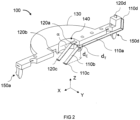
- Fig. 1 is a schematic perspective view of a status monitoring assembly 100 having a pair of monitoring contacts 110 and 120 for monitoring the operating state of an electromagnetic switch 200, such as shown in Fig. 3 .
- the electromagnetic switch 200 has a movable core or armature 210 which can move within a working region 220 of the electromagnetic switch 200 under the actuation of an electromagnetic coil (not shown) to acquire different operating positions along a central axis C of the working region 220, at least two of the acquired operating positions being associated with two different operating states of the electromagnetic switch 200.
- the movable armature 210 may be displaced along the central axis C upwards, under actuation of the energized electromagnetic coil (not shown), towards a top side of the electromagnetic switch 200 to acquire a first operating position P1 on the central axis C.
- the first operating position P1 corresponds to a distance at which the first and second monitoring contacts 110 and 120 are at rest and first enter into contact with the movable core 210 (i.e. without being pressed towards the status monitoring assembly 100 by the movable core 210).
- the electromagnetic coil is de-energized
- the movable armature 210 moves downwards the central axis C, i.e. away from the top side of the electromagnetic switch 200 onto which the status monitoring assembly 100 is to be installed, to acquire a second operating position P2 at which the electromagnetic switch 200 is in an open state.
- the closed state of the electromagnetic switch 200 (i.e. when an electric current can pass across the electromagnetic switch 200) may correspond to an operating state at which the movable core 210 is at the first operating position P1 or when the movable core 210 at a third operating position P3 along the central axis C, which is closer to the status monitoring assembly 100 than the first operating position P1 (as shown in Fig. 3 ).
- the mechanical contact between the pair of monitoring contacts 110 and 120 is first established when the movable core 210 passes the first operating position P1 and is maintained until the movable core 210 reaches the third operating position P3, causing a small deflection of the first and second monitoring contacts 110 and 120 from their rest position towards the status monitoring assembly 100.
- the status monitoring assembly 100 may be designed such that the mechanical contact with the movable core 210 is only established when the movable core 210 reaches the final closed state (i.e. the first and third operating positions P1 and P3 are made to overlap).
- the status monitoring assembly 100 since the status monitoring assembly 100 detects the position of the movable core 210 within the working region 220 of the electromagnetic switch 200 based on whether or not mechanical contact is established between the pair of monitoring contacts 110 and 120 and the movable core 210, the status monitoring assembly 100 may also be employed for monitoring electromagnetic switches with a reverse configuration, i.e. in which the first operating position P1 (or third operating position P3) corresponds to the open state and the second operating position P2 corresponds to the closed state of the electromagnetic switch.
- the status monitoring assembly 100 includes a first monitoring contact 110 and a second monitoring contact 120, both held by a support member 130 which is designed to hold the first and second monitoring contacts 110 and 120 over an open side 230 of the working region 220, facing a contact surface 240 of the movable core 210.
- the contact surface 240 of the movable core 210 corresponds to an upper side of the movable core 210 which is oriented perpendicularly to the central axis C.
- the central axis of the working region 220 is aligned with a central axis C of the support member 130.
- the status monitoring assembly 100 is preferably provided as a separate device having the support member 130 specifically adapted to be mounted on a top side of the electromagnetic switch 200.
- the support member is omitted, for e.g. the pair of monitoring contacts 110 and 120 are directly held or fixed to a body of the electromagnetic switch itself, over the open side of the core working region.
- the support member may be also provided as an integral part of the electromagnetic switch.
- the first and second monitoring contacts 110 and 120 are designed with a specific bent shape and disposed in the support member 130 so as to ensure that mechanical contact is established with the movable core 210 only when the movable core 210, actuated to move from the second operating position P2 towards the top side of the electromagnetic switch 200, reaches the first operating position P1 and is maintained at either the first operating position P1 or between the first operating position P1 and the third operating position P3, closer to the status monitoring assembly 100 than the first operating position P1.
- the first and second monitoring contacts 110 and 120 are then automatically disconnected from the movable core 210 when this is displaced in the opposite direction along the central axis C, i.e.
- the first monitoring contact 110 may be formed from a beam (or thin bar) that is bended at two spaced-apart bending zones to form an intermediate anchoring section 110a, which is the portion of the first monitoring contact 110 that is held by the support member 130.
- the anchoring section 110a is preferably flat and disposed in the support member 130 along a direction transverse to the central axis C, which coincides with the horizontal direction of the axis X in Fig. 1 .
- the first monitoring contact 110 includes a deflected section 110b, immediately adjacent to the anchoring section 110a, that is bent at one of the bending zones downwards (i.e.
- the contact angle ⁇ is the angle made by the deflected section 110b at rest (i.e. it is not being pressed by the contact with the movable core 210) and a plane containing the respective anchoring section 110a and which is transverse to the central axis C.
- the second monitoring contact 120 is designed with a shape similar to the first monitoring contact 110, including an intermediate anchoring section 110a, via which the second monitoring contact 120 is attached to the support member 130, and a deflected section 110b bended with respect to the anchoring section 110a by the contact angle ⁇ .
- a configuration may be envisaged in which the first and second monitoring contacts differ in shape, including by the value of the contact angle ⁇ between the respective deflected and anchoring sections.
- the support member 130 is adapted to hold the first and second monitoring contacts 110 and 120 at a given height from its base such that, when the status monitoring assembly 100 is mounted on the electromagnetic switch 200, the anchoring sections 110a and 120a lie at a predetermined distance (measured along the central axis C) from the core contact surface 240 when the movable core 210 in the first operating position P1.
- each of the deflected sections 110b and 120b are set based on this predetermined distance d C (or vice-versa) such that that the free-ends 110c and 120c of the deflected sections 110b and 120b (which are the ends with which the first and second monitoring contacts 110 and 120 can make mechanical contact with the core contact surface 240) are distant from the plane, transverse to the central axis C, containing the respective anchoring sections 110a and 120a by the same distance de.
- the monitoring contacts 110 and 120 touch the contact surface 240 of the movable core 210 only when the movable core 210 is in the first operating position P1 (or closer to the status monitoring assembly 100), and consequently, an electrical path is established between the pair of monitoring contacts 110 and 120, via the movable core 210, only when the electromagnetic switch 200 is in the closed state.
- the first and second monitoring contacts 110 and 122 do not touch the contact surface 240 of the movable core 210 and consequently, are electrically disconnected from each other.
- each deflected section 110b and 120b, value of contact angle ⁇ , and the separation dr with which the monitoring contacts 110 and 120 are arranged adjacent to each other in a direction transverse to both the central axis C and the anchoring sections 110a and 120a also depend on the shape and size of the core contact surface 240 of the electromagnetic switch 200 onto which the status monitoring assembly 100 will be mounted.
- the movable core 210 has a circular contact surface 240 with a central opening.
- the monitoring contacts 110 and 120 are then designed so as to extend over almost the entire area of the core contact surface 240 (which) and touch the core contact surface 240 on its second half-hemisphere, i.e. at an intermediate distance from the outer perimeter, thereby maximizing the length of the deflected sections 110b and 120b and minimizing the value of the contact angle.
- This configuration offers more stability and resilience of the mechanical contact established by the monitoring contacts 110 and 120 with the movable core 210.
- the first and second monitoring contacts 110 and 120 may also be designed so as to contact the movable core 210 on any other location on the second half-hemisphere or even at locations on the first half-hemisphere of the contact surface 240.
- Each of the deflected sections 110b and 120b is resiliently attached to the respective anchoring section 110a and 120a so that the angle made with the anchoring sections 110a and 120a may increase from the rest contact angle ⁇ and vary within a given tolerance range, thereby maintaining mechanical contact with the movable core 210 during any displacement between the first and third operating positions P1 and P3.
- each of the first and second monitoring contacts 110 and 120 may be made from a straight beam of electrically conductive material, such as a thin bar of copper or a copper alloy, which is sufficiently flexible to be bent at to form the specific shape of the monitoring contacts 110 and 120 and still maintain resilience at the bending junction between the anchoring and deflected sections against small variations in the actual operating position acquired by the movable core 210 in the electromagnetic switch 200 in the closed state (i.e. about the first operating position P1) or to return to the monitoring contacts 110 and 120 to the rest contact angle ⁇ when the movable core 210 returns to the second operating position P2.
- a straight beam of electrically conductive material such as a thin bar of copper or a copper alloy
- the first and second monitoring contacts 110 and 120 may be made of a thin bar of copper alloy having a thickness of 0.15 mm (in the direction of the central axis C), a width of 1 mm and a length of 7.5 mm, and which is bent at the junction between the anchoring and deflected sections by a contact angle ⁇ of about 36,5°.
- an external detection signal of about 3 - 5 V voltage may be applied across the pair of monitoring contacts 110 and 120, which corresponds to a detection current of about 60 - 80 mA when the monitoring contacts 110 and 120 are electrically connected via the movable core 210, for monitoring the state of the electromagnetic switch 200.
- the first and second monitoring contacts 110 and 120 are disposed in the support member 130 with the respective anchoring sections 110a and 120a parallel to each other and such as to be positioned at a same predetermined distance d C (measured in the direction of the central axis C) from the first operating position P1 when the status monitoring assembly 100 is mounted on the electromagnetic switch 200.
- d C measured in the direction of the central axis C
- the monitoring contacts of the status monitoring assembly are positioned at different distances, in the direction of the central axis C, from the first operating position P1. In this case, the length and/or contact angle ⁇ of each deflected section will be different for each monitoring contact.
- the monitoring contacts 110 and 120 in the present embodiment are designed and disposed in the support member 130 such that the respective deflected sections 110b and 120b extend in parallel and at a same distance from each other, the pair of monitoring contacts may be designed and disposed so that the respective deflected sections diverge from each other, as it will be described later with reference to the embodiment of Fig. 5 .
- the electrical contact made with the contact surface 240 may be deteriorated with use because of the dust accumulated in this region by the wear out of the armature surface 240 against the monitoring contacts 110, 120.
- the monitoring contacts 110, 120 may have a sliding contact configuration at the terminations of the deflected sections 110b, 120b so as to reduce the risk of electrical insulation appearing between the monitoring contacts 110, 120 and the armature contact surface 240.
- friction between the core contact surface 240 and the monitoring contacts 110 and 120, and consequently, wear of the contacting parts may be reduced by terminating the deflected sections 110b and 110c with curled-up free-ends 110c and 120c, respectively, which are suitably rounded to make the respective deflected sections 110b and 120b slide onto the contact surface 240 of the movable core 210, for e.g. during displacement of the core 210 within the first and third operating positions P1 and P3.
- the curled-up free-ends 110c and 120c may be formed by bending up the initially straight contact beams at a third bending zone provided near the end of the deflected sections 110b and 120b.
- the support member 130 preferably has an aperture 140, centered at a central axis of the support member 130.
- the aperture 140 becomes aligned with the central axis C of the working region 240 when the status monitoring assembly 100 is mounted on the electromagnetic switch 200.
- the central aperture 140 serves the purpose of facilitating access to the monitoring contacts 110 and 120, after these have been embedded or fixed to the support member 130 by the respective anchoring sections 110a and 120a, such as for bending the contact beams and form the deflected sections 110b and 120b and the curled-up free-end sections 110c and 120c.
- Each of the first and second monitoring contacts 110 and 120 is therefore disposed in the support member 130 with the portions corresponding to the respective deflected sections 110b and 120b arranged, at least partially, within the aperture 140.
- the respective anchoring sections 110a and 120a are partially embedded in the support member 130 with one of the respective end portions 110d and 120d bent upwards and protruding from an upper side of the support member 130 for providing a terminal connection to an electric potential.
- the end portion 110d is terminated as an input terminal to connect to an output terminal of a power supply or external monitoring device (not shown) for receiving a detection signal therefrom.
- the other monitoring contact 120 is used as an output line contact for outputting the detection signal received via the movable core 210, the end portion 120d of the second monitoring contact 120 providing a terminal end suitable for connecting to the other terminal of the power supply, or to a ground potential.
- the orientation and shape of the terminal ends 110d and 120d have the advantage that the status monitoring assembly 100 can be easily connected, using standard connectors, to an external monitoring unit or a microcontroller of a printed circuit board for monitoring and measuring the detection signal across the pair of monitoring contacts 110 and 120.
- the intermediate portions of the anchoring sections 110a and 120a are embedded within the support member 130.
- the support member 130 has a shape adapted to be mounted on the top side 230 of a housing or body 240 of the electromagnetic switch 200 and to position the monitoring contacts 110 and 120 over the open side of the working region 220, facing the contact surface 240.
- the support member 130 is preferably provided with fixation means suitable for attaching the status monitoring assembly 100 to the electromagnetic switch body 240 without the need of additional components.
- the type of fixation means may be selected depending on whether it is desired to have the status monitoring assembly 100 attached to the electromagnetic switch 200 in releasable manner or permanently fixed thereto.
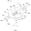
- the support member 130 may comprise one or more snap-fit features 150a - 150d shaped for snapping into corresponding mating snap-fit features 250a - 250d on the housing 240 of the electromagnetic switch 200 so as to form snap-fit joints that secure the support member 130 to the electromagnetic switch 200 in a releasable or permanent manner.
- the support member 130 is designed with a base 142 having the central aperture 140 and a pair of arms 144 and 146, extending from the left and right sides of the base 142 over the top side of the electromagnetic switch 200.
- a pair of snap-fit features 150a - 150b and 150c - 150d is provided at the respective end of each support arm 144 and 146.
- snap-fit features 150a - 150b and 150c - 150d are shaped as cantilever snap-arms with an angled undercut adapted to snap into mating cavities 250a - 250d provided in the electromagnetic switch body 250 and to form detachable snap-fit joints and secure the support member 130 to the electromagnetic switch 200.
- the status monitoring assembly 100 may be produced such that the pair of monitoring contacts are first fixed to or embedded in the support member 130 as straight contact beams, positioned adjacent to each other and which are to be shaped into the form of the first and second monitoring contacts 110 and 120 prior to assembly onto the electromagnetic switch 200.
- each straight contact beam is provided with previously defined first and second bending regions 112 and 114 that facilitate bending of the straight contact beam after being attached to the support member 130 so as to form the final shape of the deflected sections 110b, 120b.
- a section of the contact beam between one end of the straight contact beam and the first bending region 112 is defined to form the sliding free-end 110c, 120c of the first and second monitoring contacts 110, 120
- a section of the contact beam between the first and second bending regions 112 and 114 correspond to the deflected sections 110b and 120b
- the remaining section of each contact beam between the second bending region 114 and the terminal end of the beam contact includes the anchoring section 110a and 120a of the monitoring contacts 110 and 120 to be formed.
- the support member 130 with the central aperture 140 is preferably made by molded injection using methods known in the art.
- Each straight contact beam is disposed in the support member 130 so as to have the portion of each contact beam corresponding to the deflected sections 110b and 120b in the central aperture 140 and the portion corresponding to the anchoring sections 110a and 120a embedded within the support member 130.
- the straight contact beams can then be bended at the respective first bending zone 112 to form the sliding free-end sections 110c, 120c and at the second bending zone 114, in a direction transverse and away from the support member 130 and the fixed anchoring sections 110a, 120a by the contact angle ⁇ .
- the status monitoring assembly 100 can be produced in a simple manner, with a minimum of assembly steps, and still allows adjustments of the contact angle ⁇ for contacting movable cores of different diameters, at least within a given range.
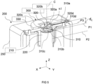
- Fig. 5 illustrates a status monitoring assembly 300 according to a second embodiment.
- the status monitoring assembly 300 includes a first monitoring contact 310 and a second monitoring contact 320, both held by a support member 330 which is also designed to hold the first and second monitoring contacts 310 and 320 over an open side 230 of the working region 220 of the movable core 210, facing the contact surface 240 of the movable core 210.
- the status monitoring assembly 300 differs from the status monitoring assembly 200 in that the support member is rigidly attached to the top side of the electromagnetic switch 200 and in the shape of the first and second monitoring contacts 310 and 320.
- the pair of monitoring contacts 310 and 320 have flat anchoring sections 310d, 320d through which the monitoring contacts 110 and 120 are fixed between the support member 330 and the top side of the electromagnetic switch 200.
- the pair of monitoring contacts 310 and 320 is shaped with deflected sections 310b and 320b, which are not only deflected downwards (along the central axis X) by a given first contact angle ⁇ 1 with respect to anchoring sections 310a and 320a, but also diverge from each other by a divergence angle ⁇ 2 in the direction transverse to the central axis C and the anchoring sections 310a and 320a.
- the length, contact angle ⁇ 1 and divergence angle ⁇ 2 are set based on the distance dc at which the anchoring sections 310a, 320a are located with respect to the first operating position P of the electromagnetic switch 200, when the status monitoring assembly 300 is arranged on top of the electromagnetic switch 200, so as to ensure that the free-end sections of the deflected sections 310b and 320b enter into mechanical contact with the movable core in the first operating position P1.
- the terminal end portions 310d and 320d of the anchoring sections 310b and 320b extend over the top side of the electromagnetic switch 200 for making an external connection, directly to a detecting signal unit or to be routed through a PCB and header (not shown).
- the remaining features and functioning of the status monitoring assembly 300 and electromagnetic switch 200 are similar to those described in the first embodiment above.
- the present invention provides a status monitoring assembly for monitoring the operating state of electromagnetic switches which uses the movable core itself for closing an electrical path between the pair of monitoring contacts.
- a status monitoring assembly for monitoring the operating state of electromagnetic switches which uses the movable core itself for closing an electrical path between the pair of monitoring contacts.
- the electromagnetic switch 200 described above may be a high-voltage contactor, and DC relay and the like.
Landscapes
- Physics & Mathematics (AREA)
- Electromagnetism (AREA)
- Switch Cases, Indication, And Locking (AREA)
Priority Applications (1)
| Application Number | Priority Date | Filing Date | Title |
|---|---|---|---|
| EP22398030.1A EP4391003A1 (de) | 2022-12-21 | 2022-12-21 | Statusüberwachungsanordnung zur überwachung eines zustands eines elektromagnetischen schalters und elektromagnetischer schalter damit |
Applications Claiming Priority (1)
| Application Number | Priority Date | Filing Date | Title |
|---|---|---|---|
| EP22398030.1A EP4391003A1 (de) | 2022-12-21 | 2022-12-21 | Statusüberwachungsanordnung zur überwachung eines zustands eines elektromagnetischen schalters und elektromagnetischer schalter damit |
Publications (1)
| Publication Number | Publication Date |
|---|---|
| EP4391003A1 true EP4391003A1 (de) | 2024-06-26 |
Family
ID=84943625
Family Applications (1)
| Application Number | Title | Priority Date | Filing Date |
|---|---|---|---|
| EP22398030.1A Pending EP4391003A1 (de) | 2022-12-21 | 2022-12-21 | Statusüberwachungsanordnung zur überwachung eines zustands eines elektromagnetischen schalters und elektromagnetischer schalter damit |
Country Status (1)
| Country | Link |
|---|---|
| EP (1) | EP4391003A1 (de) |
Citations (3)
| Publication number | Priority date | Publication date | Assignee | Title |
|---|---|---|---|---|
| US20130335174A1 (en) * | 2011-03-22 | 2013-12-19 | Panasonic Corporation | Eletromagnetic opening/closing device |
| DE102015224658A1 (de) * | 2015-12-09 | 2017-06-14 | Lisa Dräxlmaier GmbH | Elektromechanischer Schutzschalter |
| EP3432336A1 (de) * | 2016-03-18 | 2019-01-23 | BYD Company Limited | Relais |
-
2022
- 2022-12-21 EP EP22398030.1A patent/EP4391003A1/de active Pending
Patent Citations (3)
| Publication number | Priority date | Publication date | Assignee | Title |
|---|---|---|---|---|
| US20130335174A1 (en) * | 2011-03-22 | 2013-12-19 | Panasonic Corporation | Eletromagnetic opening/closing device |
| DE102015224658A1 (de) * | 2015-12-09 | 2017-06-14 | Lisa Dräxlmaier GmbH | Elektromechanischer Schutzschalter |
| EP3432336A1 (de) * | 2016-03-18 | 2019-01-23 | BYD Company Limited | Relais |
Similar Documents
| Publication | Publication Date | Title |
|---|---|---|
| RU2312437C2 (ru) | Способ и устройство для изготовления электрического соединения узлов и модулей | |
| US20020036557A1 (en) | Electromagnetic relay | |
| CN1036232C (zh) | 具有热保护的电气设备 | |
| US10541097B2 (en) | Electromechanical relay, terminal block, and electromechanical relay assembly | |
| CN102598185B (zh) | 开关设备 | |
| US5903201A (en) | Relay for high breaking capacities | |
| CN118136463A (zh) | 一种继电器 | |
| WO2012080091A1 (en) | Contact arrangement for a relay with two load current tracks and a transverse current track and relay with contact arrangement | |
| US8314670B2 (en) | Switching device | |
| EP1073159B1 (de) | Schalteinrichtung mit einem Wechselstromeinlass und einem Wechselstromschalter | |
| CN219658627U (zh) | 一种用于大电流的接触器 | |
| EP1073162B1 (de) | Schalteranordnung mit Wechselspannungseingangsstecker | |
| US7498912B2 (en) | Electromagnetic relay | |
| CN110178197A (zh) | 模块化的电流接触器组件 | |
| KR20120019066A (ko) | 릴레이 오조립 방지 구조 | |
| KR101506473B1 (ko) | 다수의 회로들을 동시에 스위칭하기 위한 전기 스위치엘리먼트, 특히 릴레이 | |
| AU2024266731B2 (en) | Electromagnetic relay | |
| JP7779725B2 (ja) | 電磁引き外し装置、回路遮断器、及び、分電盤 | |
| CN223245502U (zh) | 一种高压直流继电器 | |
| CN223785087U (zh) | 一种转辙机用无接触接点组 | |
| EP3078043B1 (de) | Kontaktsatz für hochstromrelais | |
| CN214378246U (zh) | 一种电磁继电器 | |
| US12191586B2 (en) | Electric device with a contacting device for a releasable connection of bus sections | |
| US20240282538A1 (en) | Double throw relay | |
| KR100389500B1 (ko) | 전자개폐기 |
Legal Events
| Date | Code | Title | Description |
|---|---|---|---|
| PUAI | Public reference made under article 153(3) epc to a published international application that has entered the european phase |
Free format text: ORIGINAL CODE: 0009012 |
|
| STAA | Information on the status of an ep patent application or granted ep patent |
Free format text: STATUS: THE APPLICATION HAS BEEN PUBLISHED |
|
| AK | Designated contracting states |
Kind code of ref document: A1 Designated state(s): AL AT BE BG CH CY CZ DE DK EE ES FI FR GB GR HR HU IE IS IT LI LT LU LV MC ME MK MT NL NO PL PT RO RS SE SI SK SM TR |
|
| STAA | Information on the status of an ep patent application or granted ep patent |
Free format text: STATUS: REQUEST FOR EXAMINATION WAS MADE |
|
| 17P | Request for examination filed |
Effective date: 20241212 |
|
| GRAP | Despatch of communication of intention to grant a patent |
Free format text: ORIGINAL CODE: EPIDOSNIGR1 |
|
| STAA | Information on the status of an ep patent application or granted ep patent |
Free format text: STATUS: GRANT OF PATENT IS INTENDED |
|
| RIC1 | Information provided on ipc code assigned before grant |
Ipc: H01H 50/08 20060101AFI20260306BHEP Ipc: H01H 71/46 20060101ALI20260306BHEP Ipc: H01H 50/54 20060101ALI20260306BHEP Ipc: H01H 9/16 20060101ALN20260306BHEP Ipc: H01H 1/18 20060101ALN20260306BHEP |
|
| INTG | Intention to grant announced |
Effective date: 20260331 |