EP4391124A1 - Humidificateur à membrane de pile à combustible - Google Patents
Humidificateur à membrane de pile à combustible Download PDFInfo
- Publication number
- EP4391124A1 EP4391124A1 EP22858585.7A EP22858585A EP4391124A1 EP 4391124 A1 EP4391124 A1 EP 4391124A1 EP 22858585 A EP22858585 A EP 22858585A EP 4391124 A1 EP4391124 A1 EP 4391124A1
- Authority
- EP
- European Patent Office
- Prior art keywords
- housing
- seal
- fuel cell
- cartridge
- dry air
- Prior art date
- Legal status (The legal status is an assumption and is not a legal conclusion. Google has not performed a legal analysis and makes no representation as to the accuracy of the status listed.)
- Pending
Links
Images



Classifications
-
- H—ELECTRICITY
- H01—ELECTRIC ELEMENTS
- H01M—PROCESSES OR MEANS, e.g. BATTERIES, FOR THE DIRECT CONVERSION OF CHEMICAL ENERGY INTO ELECTRICAL ENERGY
- H01M8/00—Fuel cells; Manufacture thereof
- H01M8/04—Auxiliary arrangements, e.g. for control of pressure or for circulation of fluids
- H01M8/04082—Arrangements for control of reactant parameters, e.g. pressure or concentration
- H01M8/04089—Arrangements for control of reactant parameters, e.g. pressure or concentration of gaseous reactants
- H01M8/04119—Arrangements for control of reactant parameters, e.g. pressure or concentration of gaseous reactants with simultaneous supply or evacuation of electrolyte; Humidifying or dehumidifying
- H01M8/04126—Humidifying
- H01M8/04149—Humidifying by diffusion, e.g. making use of membranes
-
- B—PERFORMING OPERATIONS; TRANSPORTING
- B01—PHYSICAL OR CHEMICAL PROCESSES OR APPARATUS IN GENERAL
- B01D—SEPARATION
- B01D63/00—Apparatus in general for separation processes using semi-permeable membranes
- B01D63/02—Hollow fibre modules
-
- B—PERFORMING OPERATIONS; TRANSPORTING
- B01—PHYSICAL OR CHEMICAL PROCESSES OR APPARATUS IN GENERAL
- B01D—SEPARATION
- B01D65/00—Accessories or auxiliary operations, in general, for separation processes or apparatus using semi-permeable membranes
- B01D65/003—Membrane bonding or sealing
-
- H—ELECTRICITY
- H01—ELECTRIC ELEMENTS
- H01M—PROCESSES OR MEANS, e.g. BATTERIES, FOR THE DIRECT CONVERSION OF CHEMICAL ENERGY INTO ELECTRICAL ENERGY
- H01M8/00—Fuel cells; Manufacture thereof
- H01M8/02—Details
- H01M8/0271—Sealing or supporting means around electrodes, matrices or membranes
- H01M8/0276—Sealing means characterised by their form
- H01M8/0278—O-rings
-
- H—ELECTRICITY
- H01—ELECTRIC ELEMENTS
- H01M—PROCESSES OR MEANS, e.g. BATTERIES, FOR THE DIRECT CONVERSION OF CHEMICAL ENERGY INTO ELECTRICAL ENERGY
- H01M8/00—Fuel cells; Manufacture thereof
- H01M8/02—Details
- H01M8/0271—Sealing or supporting means around electrodes, matrices or membranes
- H01M8/028—Sealing means characterised by their material
-
- H—ELECTRICITY
- H01—ELECTRIC ELEMENTS
- H01M—PROCESSES OR MEANS, e.g. BATTERIES, FOR THE DIRECT CONVERSION OF CHEMICAL ENERGY INTO ELECTRICAL ENERGY
- H01M8/00—Fuel cells; Manufacture thereof
- H01M8/04—Auxiliary arrangements, e.g. for control of pressure or for circulation of fluids
-
- H—ELECTRICITY
- H01—ELECTRIC ELEMENTS
- H01M—PROCESSES OR MEANS, e.g. BATTERIES, FOR THE DIRECT CONVERSION OF CHEMICAL ENERGY INTO ELECTRICAL ENERGY
- H01M8/00—Fuel cells; Manufacture thereof
- H01M8/04—Auxiliary arrangements, e.g. for control of pressure or for circulation of fluids
- H01M8/04082—Arrangements for control of reactant parameters, e.g. pressure or concentration
- H01M8/04089—Arrangements for control of reactant parameters, e.g. pressure or concentration of gaseous reactants
- H01M8/04119—Arrangements for control of reactant parameters, e.g. pressure or concentration of gaseous reactants with simultaneous supply or evacuation of electrolyte; Humidifying or dehumidifying
- H01M8/04126—Humidifying
- H01M8/04141—Humidifying by water containing exhaust gases
-
- B—PERFORMING OPERATIONS; TRANSPORTING
- B01—PHYSICAL OR CHEMICAL PROCESSES OR APPARATUS IN GENERAL
- B01D—SEPARATION
- B01D2313/00—Details relating to membrane modules or apparatus
- B01D2313/02—Specific tightening or locking mechanisms
-
- B—PERFORMING OPERATIONS; TRANSPORTING
- B01—PHYSICAL OR CHEMICAL PROCESSES OR APPARATUS IN GENERAL
- B01D—SEPARATION
- B01D2313/00—Details relating to membrane modules or apparatus
- B01D2313/04—Specific sealing means
-
- B—PERFORMING OPERATIONS; TRANSPORTING
- B01—PHYSICAL OR CHEMICAL PROCESSES OR APPARATUS IN GENERAL
- B01D—SEPARATION
- B01D2313/00—Details relating to membrane modules or apparatus
- B01D2313/04—Specific sealing means
- B01D2313/041—Gaskets or O-rings
-
- B—PERFORMING OPERATIONS; TRANSPORTING
- B01—PHYSICAL OR CHEMICAL PROCESSES OR APPARATUS IN GENERAL
- B01D—SEPARATION
- B01D2313/00—Details relating to membrane modules or apparatus
- B01D2313/20—Specific housing
-
- B—PERFORMING OPERATIONS; TRANSPORTING
- B01—PHYSICAL OR CHEMICAL PROCESSES OR APPARATUS IN GENERAL
- B01D—SEPARATION
- B01D2313/00—Details relating to membrane modules or apparatus
- B01D2313/21—Specific headers, end caps
-
- H—ELECTRICITY
- H01—ELECTRIC ELEMENTS
- H01M—PROCESSES OR MEANS, e.g. BATTERIES, FOR THE DIRECT CONVERSION OF CHEMICAL ENERGY INTO ELECTRICAL ENERGY
- H01M8/00—Fuel cells; Manufacture thereof
- H01M8/10—Fuel cells with solid electrolytes
- H01M2008/1095—Fuel cells with polymeric electrolytes
-
- Y—GENERAL TAGGING OF NEW TECHNOLOGICAL DEVELOPMENTS; GENERAL TAGGING OF CROSS-SECTIONAL TECHNOLOGIES SPANNING OVER SEVERAL SECTIONS OF THE IPC; TECHNICAL SUBJECTS COVERED BY FORMER USPC CROSS-REFERENCE ART COLLECTIONS [XRACs] AND DIGESTS
- Y02—TECHNOLOGIES OR APPLICATIONS FOR MITIGATION OR ADAPTATION AGAINST CLIMATE CHANGE
- Y02E—REDUCTION OF GREENHOUSE GAS [GHG] EMISSIONS, RELATED TO ENERGY GENERATION, TRANSMISSION OR DISTRIBUTION
- Y02E60/00—Enabling technologies; Technologies with a potential or indirect contribution to GHG emissions mitigation
- Y02E60/30—Hydrogen technology
- Y02E60/50—Fuel cells
-
- Y—GENERAL TAGGING OF NEW TECHNOLOGICAL DEVELOPMENTS; GENERAL TAGGING OF CROSS-SECTIONAL TECHNOLOGIES SPANNING OVER SEVERAL SECTIONS OF THE IPC; TECHNICAL SUBJECTS COVERED BY FORMER USPC CROSS-REFERENCE ART COLLECTIONS [XRACs] AND DIGESTS
- Y02—TECHNOLOGIES OR APPLICATIONS FOR MITIGATION OR ADAPTATION AGAINST CLIMATE CHANGE
- Y02P—CLIMATE CHANGE MITIGATION TECHNOLOGIES IN THE PRODUCTION OR PROCESSING OF GOODS
- Y02P70/00—Climate change mitigation technologies in the production process for final industrial or consumer products
- Y02P70/50—Manufacturing or production processes characterised by the final manufactured product
Definitions
- the present disclosure relates to a fuel cell membrane humidifier and, more particularly, to a fuel cell membrane humidifier, in which when manufacturing a membrane humidifier, airtightness can be maintained between an inlet housing and a cartridge, and when supplying dry air, airtightness and sealing pressure increase to stably maintain the supply of dry air and fuel cell power generation efficiency.
- a hydrogen fuel cell that utilizes electricity generated when hydrogen fuel reacts with oxygen
- various types of fuel cells such as a polymer electrolyte fuel cell, a polymer electrolyte membrane fuel cell (PEMFC), a phosphoric acid fuel cell (PAFC), and a double exchange membrane fuel cell, etc.
- a selective permeable membrane used in a membrane humidification method is preferably a hollow fiber membrane with a large permeable area per unit volume when forming a module.
- the hollow fiber membrane with a large contact surface area can be highly integrated, thereby enabling sufficient humidification of a fuel cell even with a small capacity, allowing low-cost materials to be used, and enabling reuse thereof through the humidifier by recovering moisture and heat contained in gas (or off-gas) discharged at a high temperature from the fuel cell.
- Korean Patent No. 10-2265021 discloses a membrane humidifier for a fuel cell having an assembly member provided between ends of a cap casing and a middle casing.
- the membrane humidifier for a fuel cell of the prior art described above includes a middle casing in which a plurality of hollow fiber membranes is accommodated; a cap casing coupled to the middle casing; a potting part formed on the end of the plurality of hollow fiber membranes and disposed to be spaced apart from the inner surface of the middle casing; an assembly member disposed between the ends of the cap casing and the middle casing to tightly couple the cap casing and the middle casing to each other; and a protruding part extending toward the edge part of the potting part inside the cap casing to tightly couple the cap casing and the potting part to each other, wherein the edge part of the potting part is contracted by a predetermined depth by the protruding part.
- a packing member is configured so that the ends of the cap casing and the middle casing are in direct contact with each other, and thus the membrane humidifier is presented as a design structure that maintains airtightness for a hollow fiber membrane cartridge in the process of supplying dry air for humidification into the hollow fiber membrane.
- the membrane humidifier of the prior art described above provides packing for the end of a humidification module, but when the membrane humidifier is used for a long period of time, airtightness between the cap casing to which high-pressure dry air is supplied, the middle casing, and the hollow fiber membrane cartridge deteriorates. Accordingly, leakage of dry air occurs, and this not only lowers the supply efficiency of humidifying air but also has a negative impact on fuel cell power generation efficiency.
- the present disclosure is intended to propose a fuel cell membrane humidifier, in which pressure of air introduced into a main chamber of an inlet housing when dry air is supplied is applied to a variable seal through a back pressure passage, thereby increasing airtightness between a cartridge housing and the inlet housing and stably maintaining humidifying flow of dry air to membranes.
- the present disclosure is intended to propose a fuel cell membrane humidifier, in which a circular flow or vortex of gas is formed without a dead zone inside a hollow fiber membrane cartridge to stably maintain humidifying flow of dry air to membranes, thereby stably maintaining fuel cell power generation efficiency.
- a fuel cell membrane humidifier including: a main housing having an inlet connecting portion formed on a first end portion of a body, an outlet connecting portion formed on a second end portion of the body, and a gas outlet formed on one side of the body; a hollow fiber membrane cartridge comprising a seal mount formed on an end of a cartridge housing by protruding therefrom, and a fixing layer for potting each of multiple membranes in each of opposite side ends of a body thereof, with the hollow fiber membrane cartridge installed inside the main housing; an inlet housing comprising a coupling portion mounted on the inlet connecting portion of the main housing, a seal ground portion formed inside the coupling portion, and a main chamber into which dry air is supplied through a cooler; an outlet housing comprising a coupling portion mounted on the outlet connecting portion of the main housing, a gas inflow port through which gas is provided from a hydrogen fuel cell stack, a second chamber in which humid air formed through the membranes flows, and a cartridge insertion portion to which one side end
- the fuel cell membrane humidifier wherein the variable seal includes a first groove formed in one side of the body, and a second groove formed to be spaced apart from the first groove to accommodate the dry air pressure.
- the fuel cell membrane humidifier wherein the rib has a predetermined variable angle and is formed by opening outward and extending from the second groove.
- variable seal may be formed in the cartridge insertion portion of the outlet housing.
- variable seal configured as an elastic member including a rubber material.
- the fuel cell membrane humidifier wherein the hollow fiber membrane cartridge includes: an arrangement of an upper stream distribution opening, a middle stream distribution opening, and a lower stream distribution opening formed on a first side wall of the cartridge housing; and an arrangement of an upper stream discharge opening, a middle stream discharge opening, and a lower stream discharge opening formed on a second side wall of the cartridge housing, wherein the distribution openings are formed in a multiple-layer arrangement so that an opening area increases gradually toward a lower stream side from an upper stream side, and the discharge openings are formed in a multiple-layer arrangement so that an opening area increases gradually toward an upper stream side from a lower stream side.
- ground pressure or sealing pressure increases, thereby securely maintaining airtightness and sealing performance between the inlet housing and the hollow fiber membrane cartridge and stably maintaining the flow of dry air.
- humid gas circulates inside a hollow fiber membrane module, thereby providing maximized humidification efficiency without a dead zone for dry compressed air passing through the inside of the cartridge and the hollow fiber membrane.
- FIG. 1 is a cross-sectional view of the fuel cell membrane humidifier according to an embodiment of the present disclosure disclosed in the present specification
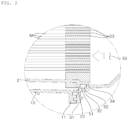
- FIG. 2 is an enlarged view of a main part of the fuel cell membrane humidifier illustrated in FIG. 1
- FIG. 3 is a schematic perspective view of a variable seal according the embodiment of the present disclosure
- FIG. 4 is a schematic diagram illustrating the initial state of the variable seal for the fuel cell membrane humidifier according to the embodiment of the present disclosure
- FIG. 5 is a schematic diagram illustrating the operating state of the variable seal when supplying dry air to the fuel cell membrane humidifier according to the embodiment of the present disclosure
- FIG. 6 is a schematic exploded perspective view of the fuel cell membrane humidifier according to the embodiment of the present disclosure.
- the fuel cell membrane humidifier includes a main housing 10, a hollow fiber membrane cartridge 20 installed inside the main housing 10, and an inlet housing 30 and an outlet housing 40 mounted respectively on opposite sides of the main housing 10.
- the main housing 10 includes an inlet connecting portion 11 formed on a first end portion of a body thereof, an outlet connecting portion 12 formed on a second end portion of the body, and a gas outlet 16 formed on one side of the body.
- the hollow fiber membrane cartridge 20 includes a seal mount 22 formed on an end portion of a cartridge housing 21 by protruding therefrom, and a fixing layer 23 for potting each of multiple membranes M on each of opposite ends of a body thereof, with the hollow fiber membrane cartridge 20 being installed inside the main housing 10.
- the main housing 10 includes a flow in section 13 having an inlet part of gas discharged from a fuel cell, a flow out section 15 having an outlet part of the gas, and one or more cartridge support parts 14; 14a, 14b formed on the inner wall of the body between the flow in section 13 and the flow out section 15.
- the hollow fiber membrane cartridge 20 includes one or more supports 24; 24a, 24b for being mounted to the cartridge support parts 14; 14a, 14b inside the main housing 10.
- the inlet housing 30 includes a coupling portion 31 mounted on the inlet connecting portion 11 of the main housing 10, a seal ground portion 32 formed inside the coupling portion 31, and a main chamber 33 into which dry air is supplied through a cooler 36.
- the inlet housing 30 is not limited to a specific shape, and as an example, as illustrated in the drawing, an outer side of the coupling portion 31 may have an open quadrangular enclosure structure, and an air inlet 37 is formed on another side of the coupling portion 31 of the inlet housing 30.
- the outlet housing 40 includes a coupling portion 41 mounted on the outlet connecting portion 12 of the main housing 10, a gas inlet part 42 through which gas is provided from a hydrogen fuel cell stack, a second chamber 43 in which humid air formed through the membranes M flows, and a cartridge insertion portion 44 to which one side end of the cartridge housing 21 is coupled.
- the outlet housing 40 may be provided with a gas inflow port 45 and an air outflow port 46 as in a prior art.
- the flow in section 13 of the main housing 10 defines a flow space through which high-pressure and high-humidity gas or water vapor formed in a hydrogen fuel cell is introduced through the gas inlet part 42 of the outlet housing 40, and the flow out section 15 defines a flow space through which the gas is discharged to the outside of the cartridge housing 21 after the gas circulates inside the cartridge housing 21 and sufficiently contacts the membranes M or the hollow fiber membrane without a dead zone.
- the inlet housing 30 and the outlet housing 40 may be respectively fixed to the inlet connecting portion 11 and the outlet connecting portion 12 of the main housing 10 through a bolting or guide-pin assembly process during cartridge assembly and a membrane humidifier manufacturing process.
- the membrane humidifier includes the variable seal 50 having a body 51 elastically grounded to the outer peripheral surface of the seal mount 21 and a rib 52 elastically transformed with respect to the body 51 and being in close contact with the seal ground portion 32, and a back pressure passage 34 communicating between the main chamber 33 and the seal ground portion 32, wherein a ground pressure of the rib 52 on the seal ground portion 32 is formed to increase in correspondence to the pressure of the dry air of the main chamber 33 introduced through the back pressure passage 34 when the dry air is supplied.
- the variable seal 50 includes a first groove 53 formed on one side of the body 51 and a second groove 54 formed to be spaced apart the first groove 53 so as to accommodate the pressure of the dry air, wherein the rib 52 has a predetermined variable angle and is formed by extending outward from the second groove 54.
- variable seal 50 is configured as an elastic member including a rubber material
- the rib 52 is formed integrally with the body 51 so that the rib can be bent to correspond to air pressure applied through the back pressure passage 34.
- the back pressure is applied to the surface of the second groove 54 and acts as a force pushing the rib 52 to the seal ground portion 32 of the inlet housing 30. Accordingly, the rib 52 has a ground pressure increased by an elastic force thereof and the above-mentioned back pressure, thereby securely maintaining airtightness and sealing performance.
- an adapter 60 by which the flow of air is induced between the hollow fiber membrane cartridge 20 mounted to the main housing 10 and the inlet housing 30 and is guided to the entrance of the membranes M of the hollow fiber membrane cartridge, and in this case, the variable seal 50 as described above may be configured on the end of the hollow fiber membrane cartridge 20.
- the hollow fiber membrane cartridge 20 includes a distribution opening arrangement 25 including an upper stream distribution opening 25a, a middle stream distribution opening 25b, and a lower stream distribution opening 25c formed on a first side wall of the cartridge housing 21, and a discharge opening arrangement 26 including an upper stream discharge opening 26a, a middle stream discharge opening 26b, and a lower stream discharge opening 26c formed on a second side wall of the cartridge housing 10.
- the distribution openings 25; 25a, 25b, and 25c are formed in a multiple-layer arrangement so that an opening area increases gradually toward a lower stream side from an upper stream side.
- the discharge openings may each have a through-hole structure in which the number of through holes increases gradually toward the lower stream distribution opening 25c from the upper stream distribution opening 25a.
- the distribution opening arrangement 25 includes through holes whose opening areas increase as a distance from the flow in section 13 increases.
- the upper stream distribution opening 25a, the middle stream distribution opening 25b, and the lower stream distribution opening 25c may each have a through-hole structure with a different opening area, and may be have various geometric modifications including a circular hole, a triangular hole, and a rectangular hole.
- the discharge openings 26: 26a, 26b, 26c are formed in a multiple-layer arrangement so that an opening area increases gradually toward a lower stream side from an upper stream side.
- the discharge openings may each have a through-hole structure in which the number of through holes increases gradually toward the lower stream discharge opening 26c from the upper stream discharge opening 26a.
- the discharge opening arrangement 26: 26a, 26b, 26c is includes through holes whose opening areas decrease as a distance from the flow out section 15 increases.
- the upper stream discharge opening 26a, the middle stream discharge opening 26b, and the lower stream discharge opening 26c may each have a through-hole structure with a different opening area, and may be have various geometric modifications including a circular hole, a triangular hole, and a rectangular hole.
- gas generated in the hydrogen fuel cell stack (not shown) is usually provided in the form of water vapor at a preset high pressure through the gas inlet part 42 of the outlet housing 40, and is primarily filled in the flow in section 13 of the main housing 10.
- the gas filled in the flow in section 13 flows into the cartridge housing 21 through the upper stream distribution opening 25a, the middle stream distribution opening 25b, and the lower stream distribution opening 25c sequentially provided on one side wall of the cartridge housing 21.
- the gas enters the flow out section 15 of the main housing 10 through the discharge openings 26a, 26b, and 26c.
- Back pressure introduced into the second groove 54 of the variable seal 50 acts as a force pushing the rib 54 outward or toward the ground portion 42 of the inlet housing 30.
- the back pressure applied to the variable seal 50 acts as horizontal and vertical forces F in the drawing through the body 51 and the rib 52, and thus the airtightness of the variable seal is securely maintained, so the flow of dry air passing through the inlet housing 30 and the membrane module M is maintained to be stable.
- dry air flowing inside the membranes or hollow fiber membranes M from the main chamber 33 of the inlet housing 30 is sufficiently humidified due to a stable flow thereof and then is provided to the hydrogen fuel cell stack through the second chamber 43 and the air outflow port 46 of the outlet housing 40 and the air outflow.
- gas supplied from the hydrogen fuel cell stack is in even contact with the entirety of the upper, middle, and lower arrangement of the membrane module M or the hollow fiber membrane module, thereby improving humidification efficiency, and the airtightness of the main chamber 33 of the inlet housing 30 is securely maintained to increase the supply efficiency of dry air, thereby greatly improving the performance of the membrane humidifier.
- the membrane humidifier In the fuel cell membrane humidifier according to the present disclosure, airtightness between the inlet housing and the cartridge can be maintained, and when dry air is supplied, airtightness and sealing pressure increase, so the membrane humidifier is useful to stably maintain dry air supply and fuel cell power generation efficiency.
Landscapes
- Chemical & Material Sciences (AREA)
- Chemical Kinetics & Catalysis (AREA)
- Life Sciences & Earth Sciences (AREA)
- Engineering & Computer Science (AREA)
- Manufacturing & Machinery (AREA)
- Sustainable Development (AREA)
- Sustainable Energy (AREA)
- Electrochemistry (AREA)
- General Chemical & Material Sciences (AREA)
- Fuel Cell (AREA)
Applications Claiming Priority (2)
| Application Number | Priority Date | Filing Date | Title |
|---|---|---|---|
| KR1020210108698A KR102607764B1 (ko) | 2021-08-18 | 2021-08-18 | 연료전지 막가습기 |
| PCT/KR2022/008160 WO2023022343A1 (fr) | 2021-08-18 | 2022-06-09 | Humidificateur à membrane de pile à combustible |
Publications (2)
| Publication Number | Publication Date |
|---|---|
| EP4391124A1 true EP4391124A1 (fr) | 2024-06-26 |
| EP4391124A4 EP4391124A4 (fr) | 2025-07-02 |
Family
ID=85239603
Family Applications (1)
| Application Number | Title | Priority Date | Filing Date |
|---|---|---|---|
| EP22858585.7A Pending EP4391124A4 (fr) | 2021-08-18 | 2022-06-09 | Humidificateur à membrane de pile à combustible |
Country Status (6)
| Country | Link |
|---|---|
| US (1) | US20240356049A1 (fr) |
| EP (1) | EP4391124A4 (fr) |
| JP (1) | JP7799036B2 (fr) |
| KR (1) | KR102607764B1 (fr) |
| CN (1) | CN117897835A (fr) |
| WO (1) | WO2023022343A1 (fr) |
Family Cites Families (13)
| Publication number | Priority date | Publication date | Assignee | Title |
|---|---|---|---|---|
| KR100458912B1 (ko) * | 1996-07-02 | 2005-06-02 | 존 웬트워드 버크넬 | 유압식 어셈블리용 실 |
| JP2006278209A (ja) | 2005-03-30 | 2006-10-12 | Toyota Motor Corp | 燃料電池システム |
| KR101185326B1 (ko) * | 2010-03-31 | 2012-09-26 | 코오롱인더스트리 주식회사 | 연료전지용 가습기 |
| DK2798691T3 (en) * | 2011-12-29 | 2019-03-18 | Kolon Inc | MEMBRANE MOISTURE |
| JP2014228105A (ja) * | 2013-05-24 | 2014-12-08 | 本田技研工業株式会社 | 高圧ガス容器および高圧ガス容器シール部のガス漏れ判定方法 |
| KR102507047B1 (ko) * | 2016-12-09 | 2023-03-06 | 현대자동차주식회사 | 연료전지용 막 가습기 |
| KR102265021B1 (ko) | 2018-06-05 | 2021-06-14 | 코오롱인더스트리 주식회사 | 연료전지용 막가습기 |
| KR102430374B1 (ko) | 2019-04-17 | 2022-08-08 | 코오롱인더스트리 주식회사 | 연료전지용 가습기 및 그것을 위한 패킹 부재 |
| JP7245930B2 (ja) * | 2019-06-25 | 2023-03-24 | コーロン インダストリーズ インク | 燃料電池用加湿器及びその製造方法 |
| KR102800842B1 (ko) * | 2019-11-29 | 2025-04-24 | 코오롱인더스트리 주식회사 | 연료전지용 가습기 |
| KR102704080B1 (ko) * | 2019-11-29 | 2024-09-05 | 코오롱인더스트리 주식회사 | 연료전지용 가습기 |
| CN212113898U (zh) * | 2020-07-01 | 2020-12-08 | 深圳伊腾迪新能源有限公司 | 一种燃料电池增湿器进气分流固定网框 |
| KR102538321B1 (ko) * | 2020-12-23 | 2023-06-01 | 엔브이에이치코리아(주) | 연료전지 막가습기 |
-
2021
- 2021-08-18 KR KR1020210108698A patent/KR102607764B1/ko active Active
-
2022
- 2022-06-09 CN CN202280059739.2A patent/CN117897835A/zh active Pending
- 2022-06-09 US US18/684,301 patent/US20240356049A1/en active Pending
- 2022-06-09 WO PCT/KR2022/008160 patent/WO2023022343A1/fr not_active Ceased
- 2022-06-09 JP JP2024509515A patent/JP7799036B2/ja active Active
- 2022-06-09 EP EP22858585.7A patent/EP4391124A4/fr active Pending
Also Published As
| Publication number | Publication date |
|---|---|
| CN117897835A (zh) | 2024-04-16 |
| US20240356049A1 (en) | 2024-10-24 |
| WO2023022343A1 (fr) | 2023-02-23 |
| EP4391124A4 (fr) | 2025-07-02 |
| KR20230026729A (ko) | 2023-02-27 |
| JP7799036B2 (ja) | 2026-01-14 |
| JP2024529745A (ja) | 2024-08-08 |
| KR102607764B1 (ko) | 2023-11-30 |
Similar Documents
| Publication | Publication Date | Title |
|---|---|---|
| JP7325163B2 (ja) | 燃料電池膜加湿器 | |
| JP7311575B2 (ja) | 燃料電池用膜加湿器 | |
| KR101393558B1 (ko) | 연료 전지용 가습장치 | |
| EP3806210B1 (fr) | Humidificateur à membrane pour pile à combustible | |
| CN114747055B (zh) | 燃料电池用加湿器 | |
| KR20190081736A (ko) | 연료전지 막가습기 | |
| KR102538321B1 (ko) | 연료전지 막가습기 | |
| JP7573766B2 (ja) | 燃料電池の膜加湿器 | |
| EP4280319A1 (fr) | Humidificateur à membrane pour pile à combustible | |
| EP2827073A1 (fr) | Humidificateur | |
| EP4273977A1 (fr) | Humidificateur à membrane de pile à combustible | |
| CN114747056B (zh) | 燃料电池用加湿器 | |
| CN116670871A (zh) | 用于燃料电池的加湿器的筒体和用于燃料电池的加湿器 | |
| CN117642893A (zh) | 膜加湿器筒体和包括该膜加湿器筒体的燃料电池膜加湿器 | |
| US20240356049A1 (en) | Fuel cell membrane humidifier | |
| JP7854517B2 (ja) | 燃料電池用加湿器のミッド-ケース及び燃料電池用加湿器 | |
| JP7573767B2 (ja) | 燃料電池の膜加湿器 | |
| CN117716549A (zh) | 膜加湿器筒体和包括该膜加湿器筒体的燃料电池膜加湿器 | |
| US20250357509A1 (en) | Fuel cell membrane humidifier | |
| EP4738488A1 (fr) | Humidificateur de pile à combustible ayant un déflecteur de type à dérivation |
Legal Events
| Date | Code | Title | Description |
|---|---|---|---|
| STAA | Information on the status of an ep patent application or granted ep patent |
Free format text: STATUS: THE INTERNATIONAL PUBLICATION HAS BEEN MADE |
|
| PUAI | Public reference made under article 153(3) epc to a published international application that has entered the european phase |
Free format text: ORIGINAL CODE: 0009012 |
|
| STAA | Information on the status of an ep patent application or granted ep patent |
Free format text: STATUS: REQUEST FOR EXAMINATION WAS MADE |
|
| 17P | Request for examination filed |
Effective date: 20240306 |
|
| AK | Designated contracting states |
Kind code of ref document: A1 Designated state(s): AL AT BE BG CH CY CZ DE DK EE ES FI FR GB GR HR HU IE IS IT LI LT LU LV MC MK MT NL NO PL PT RO RS SE SI SK SM TR |
|
| DAV | Request for validation of the european patent (deleted) | ||
| DAX | Request for extension of the european patent (deleted) | ||
| A4 | Supplementary search report drawn up and despatched |
Effective date: 20250602 |
|
| RIC1 | Information provided on ipc code assigned before grant |
Ipc: H01M 8/04 20160101ALI20250526BHEP Ipc: H01M 8/10 20160101ALI20250526BHEP Ipc: B01D 65/00 20060101ALI20250526BHEP Ipc: B01D 63/02 20060101ALI20250526BHEP Ipc: H01M 8/04119 20160101AFI20250526BHEP |
|
| STAA | Information on the status of an ep patent application or granted ep patent |
Free format text: STATUS: EXAMINATION IS IN PROGRESS |
|
| 17Q | First examination report despatched |
Effective date: 20260319 |