EP4391126A1 - Dispositif de compression pour cellules électrochimiques - Google Patents
Dispositif de compression pour cellules électrochimiques Download PDFInfo
- Publication number
- EP4391126A1 EP4391126A1 EP22307043.4A EP22307043A EP4391126A1 EP 4391126 A1 EP4391126 A1 EP 4391126A1 EP 22307043 A EP22307043 A EP 22307043A EP 4391126 A1 EP4391126 A1 EP 4391126A1
- Authority
- EP
- European Patent Office
- Prior art keywords
- stack
- compression device
- housing
- thermal
- sensor
- Prior art date
- Legal status (The legal status is an assumption and is not a legal conclusion. Google has not performed a legal analysis and makes no representation as to the accuracy of the status listed.)
- Pending
Links
Images




Classifications
-
- H—ELECTRICITY
- H01—ELECTRIC ELEMENTS
- H01M—PROCESSES OR MEANS, e.g. BATTERIES, FOR THE DIRECT CONVERSION OF CHEMICAL ENERGY INTO ELECTRICAL ENERGY
- H01M8/00—Fuel cells; Manufacture thereof
- H01M8/24—Grouping of fuel cells, e.g. stacking of fuel cells
- H01M8/2465—Details of groupings of fuel cells
- H01M8/247—Arrangements for tightening a stack, for accommodation of a stack in a tank or for assembling different tanks
- H01M8/248—Means for compression of the fuel cell stacks
-
- H—ELECTRICITY
- H01—ELECTRIC ELEMENTS
- H01M—PROCESSES OR MEANS, e.g. BATTERIES, FOR THE DIRECT CONVERSION OF CHEMICAL ENERGY INTO ELECTRICAL ENERGY
- H01M8/00—Fuel cells; Manufacture thereof
- H01M8/24—Grouping of fuel cells, e.g. stacking of fuel cells
- H01M8/241—Grouping of fuel cells, e.g. stacking of fuel cells with solid or matrix-supported electrolytes
- H01M8/2425—High-temperature cells with solid electrolytes
-
- H—ELECTRICITY
- H01—ELECTRIC ELEMENTS
- H01M—PROCESSES OR MEANS, e.g. BATTERIES, FOR THE DIRECT CONVERSION OF CHEMICAL ENERGY INTO ELECTRICAL ENERGY
- H01M8/00—Fuel cells; Manufacture thereof
- H01M8/24—Grouping of fuel cells, e.g. stacking of fuel cells
- H01M8/241—Grouping of fuel cells, e.g. stacking of fuel cells with solid or matrix-supported electrolytes
- H01M8/2425—High-temperature cells with solid electrolytes
- H01M8/2432—Grouping of unit cells of planar configuration
-
- H—ELECTRICITY
- H01—ELECTRIC ELEMENTS
- H01M—PROCESSES OR MEANS, e.g. BATTERIES, FOR THE DIRECT CONVERSION OF CHEMICAL ENERGY INTO ELECTRICAL ENERGY
- H01M8/00—Fuel cells; Manufacture thereof
- H01M8/24—Grouping of fuel cells, e.g. stacking of fuel cells
- H01M8/2457—Grouping of fuel cells, e.g. stacking of fuel cells with both reactants being gaseous or vaporised
-
- H—ELECTRICITY
- H01—ELECTRIC ELEMENTS
- H01M—PROCESSES OR MEANS, e.g. BATTERIES, FOR THE DIRECT CONVERSION OF CHEMICAL ENERGY INTO ELECTRICAL ENERGY
- H01M8/00—Fuel cells; Manufacture thereof
- H01M8/10—Fuel cells with solid electrolytes
- H01M8/12—Fuel cells with solid electrolytes operating at high temperature, e.g. with stabilised ZrO2 electrolyte
- H01M2008/1293—Fuel cells with solid oxide electrolytes
Definitions
- the present invention relates to the field of electrochemical cells, especially SOECs and SOFCs, particularly in the context of high temperature water electrolysis for the production of hydrogen.
- This reaction can be separated in two partial reactions:
- FIG. 1 shows a solid oxide electrolysis cell (SOEC) in which the reaction can be carried out.
- SOEC solid oxide electrolysis cell
- the water flow goes into the cathode 14 and the water molecules are broken down.
- the oxygen atoms become oxide ions which pass through the electrolyte 16 to the anode 12 where there is a reduction, the electrons go to the electrical circuit 18 and oxygen in the form of O 2 is collected out of the cell 10.
- H 2 stays on the cathode 14 side and is collected through a manifold where it can be stored or used.
- This reaction is made possible thanks to a potential difference between the two sides of the cell 10 applied by a power source 20.
- the cells 10 generally have a planar shape, which makes it possible to form a stack 30 comprising a plurality of cells 10 electrically connected in series.
- the cells within the stack are pressed together to improve electrical conductivity and to reduce contact resistance between the cells.
- the efficiency of the system is important for industrialization and mass production purposes. It has been found that the SOEC efficiency is optimal in a temperature range from approximately 500 to 1000°C, preferably from approximately 650 to 850°C. This is because it is more advantageous to electrolyze vapor water (steam) than liquid water, and because part of the energy required for the reaction can be brought in the form of heat rather than electric power. This implies that the stack of cells needs to be placed in an oven. In this context, it is particularly challenging to properly press the stack and monitor this compression at such high operating temperature range. In particular, sensors for monitoring stack compression cannot usually operate in the temperature range in which an SOEC is used.
- a solid oxide fuel cell (SOFC) is operated in a reverse manner relative to an SOEC; namely, the cell is fed with hydrogen and oxygen and produces electrical power.
- SOFCs are generally similar to those of SOECs.
- the invention relates to the following items:
- the present invention provides a compression device for compressing a stack of electrochemical cells within a thermal enclosure, as well as a sensor for sensing the compression force, located outside the thermal enclosure.
- One or more thermal protection features may be located along the compression device and/or between the sensor and the inside of the thermal enclosure.
- the one or more thermal protection features allow the sensor to operate at a relatively low temperature, the sensor being thus protected and isolated from the heat of the thermal enclosure. Therefore, compression is provided to the stack and the compression can be adequately monitored.
- the system may include a combination of components of high and low thermal conductivity in a high temperature environment, thereby ensuring optimal mechanical and thermal protection functions. Consequently, it is possible to monitor the compressive force applied to the stack while also ensuring protection of the components of the system that may become easily damaged when exposed to high temperatures, such as the sensor.
- the system may in particular be a water electrolysis system for producing hydrogen, or a fuel cell system for producing electrical power.
- the system may be in particular a High Temperature Electrolysis (HTE) system, or a High Temperature Steam Electrolysis (HTSE) system.
- HTE High Temperature Electrolysis
- HTSE High Temperature Steam Electrolysis
- the system comprises a thermal enclosure or hotbox (e.g . oven) 120.
- the thermal enclosure 120 may comprise one or more heating elements; it may be an industrial oven; it may be capable of heating one or more electrolytic stacks and capable of operating at high temperatures, ranging for example from 500 to 1000°C or from 650 to 850°C, for example operating at a temperature of approximately 800°C.
- the materials of components of the system may be selected for their mechanical properties and thermal properties, according to their location in the system and their function. Components of the system may be able to sustain a high temperature environment without experiencing significant changes to their properties.
- the system comprises at least one stack 100 comprising at least one electrochemical cell 101.
- the stacks 100 are inside the thermal enclosure 120.
- Each electrochemical cell 101 may comprise an electrolyte and two electrodes.
- Each electrochemical cell 101 may in particular be an electrolytic cell, i.e. a cell configured for electrolysis, preferably water electrolysis.
- the electrochemical cells 101 may preferably be SOEC cells. Additionally or alternatively, the electrolytic cells may be SOFC cells.
- Each stack 100 may comprise multiple electrochemical cells 101.
- the stack 100 may comprise a stacking or piling of electrochemical cells 101 along a stacking direction.
- Each cell may be a planar cell.
- the respective stacks 100 may comprise the same number of cells or a different number of cells.
- Each stack 100 may be associated with electrical circuitry, as well as with fluid feeding and fluid collecting elements.
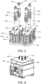
- multiple stacks 100 When multiple stacks 100 are present in the thermal enclosure 120, they may preferably be placed side by side as shown in FIG. 3 , i.e. the layers of the cells 101 of the respective stacks 100 may be substantially aligned or parallel.
- the system comprises at least one compression device 118 for applying a compressive force to each stack 100, wherein the force has a component along the stacking direction, and is preferably parallel to the stacking direction.
- the compression device 118 may maintain the stack 100 in a compressed state allowing a good electrical and/or thermal contact between the various layers (i.e. of stacked cells) of the stack.
- the compression device 118 may maintain a compressive force on the stack 100 to keep the cells 101 compressed so as to allow the passage of electric current, enable a good electrical contact between the cells, enable the passage of fluids through the stack and to avoid gas leaks.
- the compression device 118 may apply a compressive force to the stack 100 in a direction perpendicular to the planar surface of the cells 101.
- compression device 118 there can be a single compression device 118 per stack 100, as illustrated herein. Alternatively, there can be more than one compression devices per stack.
- Each compression device 118 is positioned through an opening of a wall of the thermal enclosure 120 as shown on FIG. 4 and comprises a first part outside (i.e. protruding out of) the thermal enclosure 120 and a second part inside (i.e. inserted in) the thermal enclosure 120.
- the system comprises a sensor 112 for sensing the compression force applied to the stack 100.
- the sensor 112 is attached to the first part of the compression device 118.
- the sensor 112 may have an operating temperature lower than that of the thermal enclosure 120.
- the system comprises one or more thermal protection features located along the compression device 118 and between the sensor 112 and the at least one stack 100. At least one of the thermal protection features may be inside the thermal enclosure 120. Additionally or alternatively, at least one of the thermal protection features may be outside the thermal enclosure 120. At least one of the thermal protection features may be a cooling feature.
- the thermal protection features in this case may comprise elements for cooling or ventilating the compression device 118, preferably for cooling or ventilating an internal portion of the compression device 118. At least one of the one or more thermal protection features may be a thermal insulation feature. The one or more thermal protection features in this case may facilitate insulating the sensor 112 from the inside of the thermal enclosure 120.
- each compression device 118 may be elongated along a main axis 113 which is perpendicular to the planar surfaces of the cells 101.
- the term “ distal” refers to the orientation towards the stack 100 (illustrated by the arrow 105 on FIG. 3 ), and the term “proximal” refers to the orientation away from the stack 100 (direction opposite to the arrow 105).
- the compression device 118 may comprise a housing 140 enclosing a mechanical pusher 146 and a biasing member 134.
- the mechanical pusher 146 may extend along the main axis 113 and may be slidable within the housing 140 along this main axis 113.
- the mechanical pusher 146 and the housing 140 may have a generally cylindrical (respectively, tubular) shape along the main axis 113.
- the mechanical pusher 146 may be positioned distally relative to the biasing member 134.
- the biasing member 134 may be configured for biasing the mechanical pusher 146 towards the stack 100.
- a disk element 138 may be provided at the interface between the biasing member 134 and the mechanical pusher 146, in order to make sure that the biasing force exerted by the biasing member 134 is transmitted to the mechanical pusher 146.
- the biasing member 134 may be configured for biasing the housing 140 away from the stack 100.
- the biasing member 134 may press on the mechanical pusher 146 in the distal direction, while exerting a force on the housing 140 in the proximal direction.
- the biasing member 134 may be partly or preferably fully outside of the thermal enclosure 120.
- the mechanical pusher 146 may be fully inside the thermal enclosure 120, or preferably only partly inside the thermal enclosure 120.
- the compression device 118 may be mounted to a compression plate 116. More specifically, the distal end of the mechanical pusher 146 may bear against the compression plate 116, the compression plate 116 being configured to transfer and distribute the compressive force (along the arrow 105) from the mechanical pusher 146 to the stack 100. As the compression device 118 applies a compressive force to the stack 100, the contact between the mechanical pusher 146 and the compression plate 116 can allow for a homogenous repartition of the force from the mechanical pusher 146 to the stack 100, i.e. a substantially equal distribution of the force across the stack 100, enabling a more effective contact between each respective cell 101 of the stack 100 as they are compressed.
- the compression device 118 may be mounted on a frame fixedly arranged in the system.
- the frame may include a pulling plate 117, a base plate 107 and struts 103 as will be described in more detail below.
- the frame may have any configuration that allows it to remain in a fixed position within the system, especially relative to the stack. For instance it could consist of a plate only that is fixed within the thermal enclosure via any appropriate means.
- the base plate 107 may be provided on the other side of the stack 100, relative to the compression plate 116. The stack may thus be sandwiched and compressed between the compression plate 116 and the base plate 107.
- the compression device 118 may further be fixedly mounted to the pulling plate 117, preferably via the housing 140.
- the pulling plate may be fixedly connected to the base plate 107, preferably by one or more struts 103 which may for example be positioned around the stack 100 as shown on FIG. 3 .
- the pulling plate may allow for the recovery of the forces generated by the biasing member 134 and mechanical pusher 146 and transmitted in the opposite direction through the base plate 107 and struts 103.
- the forces may in this case be further transmitted to the housing 140 which is attached to the pulling plate 117.
- Both the compression plate 116 and the pulling plate 117 may be in the thermal enclosure 120.
- Both the compression plate 116 and the pulling plate 117 may be on the same side of the stack 100 (while the base plate 107 is on the other side of the stack 100).
- the compression plate 116 may be positioned distally relative to the pulling plate 117 (i.e. the compression plate 116 may be between the stack 100 and the pulling plate 117).
- a gap may be provided between the pulling plate 117 and the compression plate 116.
- a through hole may be provided in the pulling plate 117 so that the compression device 118 may extend through this through hole and down to the compression plate 117, as shown in FIG. 11 .
- the compression plate 116, pulling plate 117 and base plate 107 may be of any shape, such as a triangular shape, square shape, rectangular shape, circular shape or other.
- the pulling plate 117, in the illustrated example, may be of a triangular shape.
- a distal end component 176 may be provided at an interface between the mechanical pusher 146 and the compression plate 116 a shown on FIG. 11 .
- the distal end component 176 may be accommodated into a recess in the compression plate 116, the recess guiding the mechanical pusher 146 and thereby facilitating correctly applying (and in particular orienting) the force to the stack 100.
- the distal end component 176 may have a convex surface, such as a rounded surface, engaged with a concave surface in a recess in the compression plate 116.
- the distal end component 176 may also comprise a notch for accommodating the distal end of the mechanical pusher 146.
- the mechanical pusher 146 may apply the compressive force to the compression plate 116 via the distal end component 176.
- An anchoring piece 102 may be provided to fixedly connect the housing 140 of the compression device 118 to the pulling plate 117.
- the anchoring piece 102 may be an annular piece fixed within the through hole of the pulling plate 117.
- the outer periphery of the housing 140 may be at least partly inserted within the anchoring piece 102 and fixed thereto.
- the anchoring piece 102 may for example be fixed to the pulling plate 117 via a locking ring or bearing 174 inserted between the pulling plate 117 and the anchoring piece 102 as shown on FIG. 13C .
- a stopper ring 172 may be present between the anchoring piece 102 and the housing 140, as illustrated on FIG. 13A .
- This stopper ring 172 may be positioned in a circumferential groove on an exterior surface of the housing 140.
- the stopper ring 172 may be made of two half rings which are assembled around the housing 140.
- the anchoring piece 102 may be slid onto the housing 140 from the proximal end and abut on the stopper ring 172. Once the assembling is complete, and in use, a pulling force (oriented opposite to the compressive force) acts on the housing 140 and the housing 140 is maintained in a fixed position relative to the anchoring piece 102 owing to the abutment on the stopper ring 172.
- the centering tool 182 is visible on FIG. 13C .
- the centering tool 182 may be an annular tool comprised of two semi-annular elements interfaced between the distal end component 176 and the anchoring piece 102. This centering tool 182 may be removed once the assembling of the compression device 118 is complete.
- the biasing member 134 may be in the form of a compression spring.
- the biasing member 134 may bear against the mechanical pusher 146 at a proximal end thereof.
- the mechanical pusher 146 comprises a first (distal) portion 161, a second (middle) portion 160, which will be described in more detail below, as well as a third (proximal) portion 139.
- This third portion 139 is an interface element between the biasing member 134 and the rest of the mechanical pusher 146, which transmits the compressive force from the biasing member 134 to the mechanical pusher 146.
- the third portion 139 can comprise a (e.g.
- the distal end of the third portion 139 and the proximal end of the second portion 160 may mate together.
- the distal end of the third portion 139 may comprise a recess in which a protrusion at the proximal end of the second portion 160 may be inserted - the opposite being of course also possible.
- a nut 114 may be mounted on a proximal end of the housing 140.
- the nut may be configured for adjusting the compressive force exerted by the biasing member 134 on the mechanical pusher 146 (preferably, manually).
- the nut may be threadedly engaged with an outer surface of the housing 140.
- the nut 114 may be helically movable along the main axis relative to the main housing 140.
- the biasing member 134 may press against the nut in the proximal direction.
- the nut 114 when the nut 114 is rotated (such as manually rotated): either it is screwed distally, so that the compression force exerted by the biasing member 134 increases; or it is screwed proximally, so that the compression force exerted by the biasing member 134 decreases.
- the housing 140 may comprise several parts, which may be fixed together. As illustrated, the housing 140 may comprise a distal part 104 surrounding the mechanical pusher 146 (this distal part 104 may be fixedly engaged with the pulling plate 117 via the anchoring piece 102); and a proximal part 109 surrounding the biasing member 134. The nut 114 may be threadedly engaged with the proximal part 109.
- the housing 140 may also comprise an interconnecting part 137 which may interconnect the distal part 104 with the proximal part 109. For example, as illustrated, the interconnecting part 137 may be connected at a proximal end of the distal part 104 and at a distal end of the proximal part 109.
- the interconnecting part 137 may surround a portion of both the distal part 104 and proximal part 109.
- the interconnecting part 137 may enclose a distal end of the biasing member 134 and a proximal end of the mechanical pusher 146 (e.g. the above-described third portion 139 as well as optionally a proximal length of the above-described second portion 160 of the mechanical pusher 146).
- the biasing member 134 (preferably the compression spring) may be prestressed in the compression device, preferably before the thermal enclosure starts to heat up.
- the biasing member 134 may be prestressed with a force ranging between 3000 and 6000 N, for example between 4000 and 5000 N.
- the compressive force applied by the biasing member 134 may be reduced due to thermal dilatation. It may range for example between 3500 and 4500 N.
- a sensor 112 is provided at a proximal end of the compression device 118 (outside the thermal enclosure 120), for sensing the compression force applied to the stack 100.
- the sensor 112 may be a mechanical sensor.
- the sensor 112 may sit upon a sensor base housing 110.
- the sensor base housing 110 may be fixedly mounted at the proximal end of the nut 114.
- the nut 114 is preferably fully outside the thermal enclosure 120.
- the sensor may comprise a sensor cover 157 and a sensing component 156.
- the sensing component 156 may be surrounded by a peripheral sensor wall 111.
- the sensing component 156 may in contact with a bearing 166.
- the sensor cover 157 may be placed proximally relative to the sensing component 156, while the bearing 166 may be placed distally.
- the peripheral sensor wall 111 may have an annular shape and surround the sensing component 156.
- the bearing 166 may be at an interface between the biasing member 134 and the sensor 112.
- the bearing 166 may comprise a (e.g. central) radially extending flange (or alternatively, radially extending arms) upon which the coils of the compression spring may bear.
- the biasing member 134 thus biases the bearing 166 proximally.
- the applied force is transmitted to the sensor 112.
- the sensing element 156 may mate with the bearing 166. As illustrated, a distal protrusion of the sensing element 156 may be inserted in a mating proximal recess in the bearing 166.
- the sensing element 156 may be fixed to the sensor cover 157, which is itself fixed to the peripheral sensor wall 111.
- the peripheral sensor wall 111 may comprise a radially extending flange, preferably at a distal end thereof.
- the sensor base housing 110 may have an annular shape and may partly surround the peripheral sensor wall 111.
- the peripheral sensor wall 111 may be secured against axial movement relative to the sensor base housing 110, but may be freely rotatable relative to the sensor base housing 110. This can be accomplished using a dedicated interface between the sensor base housing 110 and peripheral sensor wall 111, such as a rolling bearing 153 (or thrust bearing).
- the rolling bearing 153 can be sandwiched between the sensor base housing 110 (on the proximal side) and the flange of the peripheral sensor wall 111 (distal side). Therefore, when the nut 114 is rotated, the sensor base housing 110 rotates as well, but the sensor 112 itself does not rotate. This prevents any damage to the sensor's electrical wiring by twisting (not shown on the drawings).
- the sensor 112 and in particular the sensing element 156 senses the force applied between the biasing member 134 and the sensor base housing 110 / nut 113 / housing 140.
- thermal protection features may include thermal insulation and/or cooling features.
- thermal protection feature any element having a function of preventing transmission of excessive heat from the inside of the thermal enclosure 120 to the sensor 112. This prevention may be effected through a specific geometric shape and/or through a specific choice of material.
- Thermal insulation features may include one or more elements, in particular element of the compression device 118, made of a material having low thermal conductivity, such as a ceramic material.
- the material having low thermal conductivity may have a thermal conductivity at 20°C of less than 10 Wm -1 K -1 , preferably less than 5 Wm -1 K -1 more preferably less than 3 Wm -1 K -1 or less than 2 Wm -1 K -1 .
- the thermal conductivity at 20°C may be from 0.5 to 10 Wm -1 K -1 , preferably from 1 to 5 Wm -1 K -1 , more preferably from 1 to 3 Wm -1 K -1 and even more preferably from 1.5 to 2 Wm -1 K -1 .
- Thermal conductivity may be measured according to ASTM C1470-20.
- the material preferably withstands a temperature of up to 1000°C.
- Cooling features may preferably include passive cooling features, in particular for facilitating the natural convection of air within the compression device 118.
- At least a portion of a mechanical pusher 146 of the compression device 118 may be made of a material having low thermal conductivity and high mechanical resistance, such as a ceramic material.
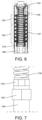
- the mechanical pusher 146 comprises a first (distal) portion 161 and a second (middle) portion 160 as already indicated above and as illustrated in FIG. 12 .
- the first portion 161 may be made of a metal (including an alloy, such as an austenitic nickel-chrome superalloy, for example of the Inconel ® brand).
- the second portion 160 may be made of a ceramic material.
- the second portion 160 may be made of material having low thermal conductivity, as described above..
- the distal end of the second portion 160 may bear against the proximal end of the first portion 161.
- the distal end of the second portion 160 may mate with the proximal end of the first portion 161.
- the proximal end of the first portion 161 may comprise a recess in which a protrusion at the proximal end of the second portion 160 may be inserted - the opposite being of course also possible.
- the portions may be maintained assembled in compression.
- the second portion 160 may be positioned through the wall of the thermal enclosure 120.
- the first portion 161 may be positioned through the wall of the thermal enclosure 120.
- the first portion 161 may be of a length (along the main axis) longer than that of the second portion 160.
- the second portion 160 may significantly block the conduction of heat from the inside of the thermal enclosure 120 to the biasing member 134 and ultimately to the sensor 112.
- the material of the second portion 160 preferably has high mechanical resistance since it is subjected to high compressive force.
- this material may have a resistance to compression of at least 200 MPa, or at least 300 MPa, or at least 400 MPa (such as from 200 to 1000 MPa, or from 400 to 800 MPa, or from 450 to 600 MPa).
- This material may have a resistance to flexion of at least 50 MPa, or at least 70 MPa, or at least 90 MPa (such as from 50 to 250 MPa, or from 70 to 200 MPa, or from 90 to 150 MPa).
- This material may have an elastic modulus (Young's modulus) at 20 °C of at least 20 GPa, or at least 40 GPa, or at least 60 GPa (for example from 20 to 120 GPa, or from 40 to 100 GPa, or from 60 to 80 GPa).
- Young's modulus Young's modulus
- Vitro800 is an example of a commercial ceramic material (marketed by Final Advanced Materials) which may be used for the second portion 160.
- one or more thermally insulating rings may be provided in the compression device 118.
- the one or more thermally insulated rings may act as thermal bridge breakers.
- the compression device 118 may comprise at least one heat breaker ring 142 around the housing 140, preferably positioned outside the thermal enclosure 120.
- An example of a heat breaker ring 142 can be seen in FIG. 7 , FIG. 8B and FIG. 11 .
- the heat breaker ring 142 may have a thermal conductivity within the ranges described above.
- the heat breaker ring 142 may be made of a ceramic material.
- the heat breaker ring 142 may be positioned in a circumferential groove on an exterior surface of the housing 140.
- the heat breaker ring 142 may be made of two half rings which are assembled within the circumferential groove.
- the heat breaker ring 142 may in particular be positioned around the distal part 104 of the housing 140, more preferably close to the proximal end of this distal part 104.
- the heat breaker ring may radially protrude from the circumferential groove.
- the heat breaker ring 142 may surround the second portion 160 of the mechanical pusher 146 (with the housing in-between).
- the housing 140 (and in particular the distal part 104) may be made of a material such as a metal, including an alloy, such as an austenitic nickel-chrome superalloy, for example of the Inconel ® brand. Generally, the housing 140 (and in particular the distal part 104) is not made of a ceramic material. The choice of material for the housing 140 (and in particular the distal part 104) may be primarily dictated by a desired mechanical performance in traction. This generally implies that the housing 140 (and in particular the distal part 104) has a higher thermal conductivity than the low thermal conductivity materials mentioned above.
- the housing 140 may have a reduced thickness in the area where the heat breaker ring 142 is present, which limits the transmission of heat by conduction from the thermal enclosure 120 to the sensor 112 via the housing.
- the stopper ring 172 described above may also be a heat breaker ring (alternatively or additionally) present in the system, between the anchoring piece 102 and the housing 140 (in particular the distal part 104), as illustrated on FIG. 13A .
- the stopper ring 172 may have a thermal conductivity within the ranges described above.
- the stopper ring 172 may be made of a ceramic material.
- the housing 140 may have a reduced thickness in the area where the stopper ring 172 is present, which limits the transmission of heat by conduction.
- one or more sealing members may be provided in the compression device 118.
- the one or more sealing members may act to prevent or reduce the flow of hot air within the compression device towards the sensor 112.
- the one or more sealing members may in particular be positioned within the housing 140.
- One sealing member in particular may be a sealing ring 178 as shown in FIG. 7 and FIG. 13B .
- this sealing ring 178 may be provided at a proximal end of the first (distal) part 104 of the housing.
- the sealing ring 178 may comprise an annular portion inserted between the housing 140 and the mechanical pusher 146, for example between the first part 104 of the housing and the third portion 139 of the mechanical pusher 146. It may also have a radially extending flange covering the proximal end of the first part 104 of the housing 140.
- the sealing ring 178 may for example be made of a ceramic material or of a metal (including an alloy).
- the sealing ring 178 has a low thermal conductivity within the ranges described above.
- the system may comprise a thermally insulating material as a thermal seal in the opening of the thermal enclosure around the compression device, in order to reduce heat loss from the thermal enclosure.
- the thermally insulating material may be a ceramic wool (i.e. wool with a very low thermal conductivity and which can withstand temperature up to 1000°C).
- the thermally insulating material may have a thermal conductivity at 800°C of less than 0.5 Wm -1 K -1 , preferably of less than 0.2 Wm -1 K -1 , more preferably of less than 0.1 Wm -1 K -1 , most preferably of less than 0.04 Wm -1 K -1 .
- the system may comprise a thermal insulation feature at the interface between the mechanical pusher 146 and the compression plate 116 so as to break the heat conduction path at this junction.
- a thermal insulation feature at the interface between the mechanical pusher 146 and the compression plate 116 so as to break the heat conduction path at this junction.
- This can be achieved, for example, by providing a low thermal conductivity material (as defined above) between the mechanical pusher 146 and the compression plate 116.
- the distal end component 176 described above may act as such a thermal insulation feature.
- this can be achieved by machining the compression plate 116 so as to create a relatively high roughness surface. Providing high roughness on the surface may ensure continued optimal mechanical function while mitigating thermal conduction from the stack 100 to the mechanical pusher 146.
- the roughness Ra of the surface of the compression plate 116 can range from 1.6 to 3.2 ⁇ m.
- the roughness Ra may be measured in accordance with ISO 4287:2000.
- these may comprise ventilation holes and/or a heat sink, positioned outside the thermal enclosure 120. These cooling features may assist in cooling the compression device 118 by ambient air.
- the housing 140 and/or the nut 113 may comprise ventilation holes.
- the second (proximal) part 109 of the housing may comprise ventilation holes; and/or the interconnecting part 137 of the housing may comprise ventilation holes; and/or the nut 114 may comprise ventilation holes.
- the ventilation holes may comprise one or more inlets 148 and one or more outlets 152.
- the outlets 152 may for example be located proximal relative to the inlets 148. Therefore, air may enter the housing at one or more distal positions (see the arrows 164 on FIG.
- the interconnecting part 137 may comprise a plurality of inlets 148 and the nut 114 may comprise a plurality of outlets 152.
- the nut outlets 152 may be provided at an angle or slant inside the nut.
- the nut ventilation holes 152 may be perpendicular to the main axis 113.
- the housing 140 in particular the interconnecting part 137, may comprise a plurality of ventilation holes 148 longitudinally spaced along the main axis. Air may enter the housing via some of these holes 128, flow along the main axis, and exit the housing via other holes 130, thus also ensuring the cooling function.
- a model of such ventilation within the interconnecting part 137 of the housing can be seen on FIG. 6 .
- a sealing ring 124 may be provided within the housing proximal to the ventilation holes 128, 130 in the interconnecting part 137, to prevent relatively hot air from flowing further proximally.
- a heat sink may be provided around the housing, outside the thermal enclosure.
- the heat sink may be in the form of fins or elongated arms directly protruding from a wall of the housing.
- the heat sink may be present on a cover sleeve fit around a portion of the housing.
- the compression device 118 may comprise a cover sleeve 108 fixed around the housing 140, outside of the thermal enclosure.
- the cover sleeve 108 may for example be made of a metal, for example aluminum.
- the cover sleeve 108 may be fit around the interconnecting part 137 of the housing.
- the cover sleeve 108 may comprise holes aligned with these ventilation holes so that they are not obstructed by the cover sleeve 108.
- the cover sleeve 108 may comprise a heat sink 106, preferably in the form of a plurality of fins 151.
- the fins 151 can for example extend along the main axis and be circumferentially arranged on the cover sleeve 108. Alternatively, the fins could also be in the form of circumferential flanges, longitudinally spaced apart. Other protruding features such as arms or the like can also be used for the heat sink 106.
- the heat sink 106 can facilitate the transfer of heat from the thermal enclosure to the environment.
- the fins 151 may preferably be made of metal, for example aluminum, and may be welded or soldered to the cover sleeve 108.
- the fins are preferably made of a high thermal conductivity material (the thermal conductivity is preferably more than 50 Wm -1 K -1 , more preferably more than 100 Wm -1 K -1 ) so as to facilitate heat conduction through the fins and cooling by the surrounding air.
- Holes may be present between the fins.
- a line of holes e.g. 5 or 6 holes aligned along the main axis is provided between every pair of adjacent fins, corresponding to similar ventilation holes in the interconnecting part 137.
- a unitary member may be provided (i.e . for example the heat sink, e.g . fins, may be directly fixed to the interconnecting part), the geometry being otherwise similar to what has been described above.
- Various surface treatments may be provided to further reduce the transfer of heat from the thermal enclosure to the sensor.
- some or all components of the system may receive a surface treatment so as to reduce their emissivity.
- a low emissivity property can advantageously allow for reducing the heat transfer between the different parts by radiation, which is likely to occur between components subjected to high temperatures.
- the surface treatment may comprise a polishing step.
- the surface treatment may comprise providing a coating or paint, such as a metal coating.
- the metal coating may have a thickness from 1 to 10 ⁇ m.
- emissivity at a temperature of 500°C may be reduced by a factor of 2 to 10, for example by a factor of 3 to 5, due to the surface treatment.
- the senor may be maintained and may operate at a temperature of less than 200°C, preferably less than 150°C or even less than 100°C.
- Exemplary ranges of temperature operation for the sensor are from 50 to 200°C, preferably from 70 to 150°C.
- the arrows 132 indicate the general direction of heat flow throughout the compression device 118 in FIG. 8A and FIG. 8B .
- These drawings show a numerical simulation of the temperature gradient across the mechanical pusher 146 and biasing member 134.
Landscapes
- Life Sciences & Earth Sciences (AREA)
- Engineering & Computer Science (AREA)
- Manufacturing & Machinery (AREA)
- Sustainable Development (AREA)
- Sustainable Energy (AREA)
- Chemical & Material Sciences (AREA)
- Chemical Kinetics & Catalysis (AREA)
- Electrochemistry (AREA)
- General Chemical & Material Sciences (AREA)
- Electrolytic Production Of Non-Metals, Compounds, Apparatuses Therefor (AREA)
Priority Applications (2)
| Application Number | Priority Date | Filing Date | Title |
|---|---|---|---|
| EP22307043.4A EP4391126A1 (fr) | 2022-12-24 | 2022-12-24 | Dispositif de compression pour cellules électrochimiques |
| PCT/EP2023/086397 WO2024133106A1 (fr) | 2022-12-24 | 2023-12-18 | Dispositif de compression pour cellules électrochimiques |
Applications Claiming Priority (1)
| Application Number | Priority Date | Filing Date | Title |
|---|---|---|---|
| EP22307043.4A EP4391126A1 (fr) | 2022-12-24 | 2022-12-24 | Dispositif de compression pour cellules électrochimiques |
Publications (1)
| Publication Number | Publication Date |
|---|---|
| EP4391126A1 true EP4391126A1 (fr) | 2024-06-26 |
Family
ID=85017680
Family Applications (1)
| Application Number | Title | Priority Date | Filing Date |
|---|---|---|---|
| EP22307043.4A Pending EP4391126A1 (fr) | 2022-12-24 | 2022-12-24 | Dispositif de compression pour cellules électrochimiques |
Country Status (2)
| Country | Link |
|---|---|
| EP (1) | EP4391126A1 (fr) |
| WO (1) | WO2024133106A1 (fr) |
Citations (15)
| Publication number | Priority date | Publication date | Assignee | Title |
|---|---|---|---|---|
| US6645659B2 (en) * | 2000-07-19 | 2003-11-11 | Toyota Jidosha Kabushiki Kaisha | Fuel cell apparatus |
| US6797425B2 (en) | 2002-12-24 | 2004-09-28 | Fuelcell Energy, Inc. | Fuel cell stack compressive loading system |
| US6835486B2 (en) | 2001-03-27 | 2004-12-28 | Fuelcell Energy, Ltd. | SOFC stack with thermal compression |
| KR20100136723A (ko) * | 2009-06-19 | 2010-12-29 | 한국전력공사 | 자동 연료전지 스택 가압 장치 및 그 제어방법 |
| KR101102177B1 (ko) * | 2009-08-13 | 2012-01-02 | 두산중공업 주식회사 | 연료전지의 면압제어장치 |
| JP5188755B2 (ja) | 2006-07-14 | 2013-04-24 | トプサー・フューエル・セル・アクチエゼルスカベット | 圧縮アセンブリ、固体酸化物燃料電池スタック、固体酸化物燃料電池の圧縮方法及びそれの使用 |
| JP5283634B2 (ja) | 2007-01-26 | 2013-09-04 | トプサー・フューエル・セル・アクチエゼルスカベット | 燃料電池スタックのクランプ構造および固体酸化物型燃料電池スタック |
| US8877399B2 (en) | 2011-01-06 | 2014-11-04 | Bloom Energy Corporation | SOFC hot box components |
| US9559378B2 (en) | 2011-06-28 | 2017-01-31 | Toyota Jidosha Kabushiki Kaisha | Fuel cell stack case with pressure plate |
| US20170140233A1 (en) | 2015-11-13 | 2017-05-18 | Fingerprint Cards Ab | Method and system for calibration of a fingerprint sensing device |
| US9812729B2 (en) | 2009-09-30 | 2017-11-07 | Bloom Energy Corporation | Fuel cell stack compression devices and methods |
| US20190088974A1 (en) | 2017-09-19 | 2019-03-21 | Phillips 66 Company | Method for compressing a solid oxide fuel cell stack |
| EP3679620A1 (fr) | 2017-10-26 | 2020-07-15 | Commissariat à l'énergie atomique et aux énergies alternatives | Ensemble d'un empilement à oxydes solides de type soec/sofc et d'un système de serrage avec système de surchauffe des gaz intégré |
| EP3707296A1 (fr) | 2017-12-19 | 2020-09-16 | Commissariat à l'énergie atomique et aux énergies alternatives | Ensemble d'un empilement à oxydes solides de type soec/sofc, d'un système de serrage et d'un système de couplage étanche |
| US20220115685A1 (en) * | 2019-02-07 | 2022-04-14 | Eh Group Engineering Ag | Fuel cell stack with compression means |
-
2022
- 2022-12-24 EP EP22307043.4A patent/EP4391126A1/fr active Pending
-
2023
- 2023-12-18 WO PCT/EP2023/086397 patent/WO2024133106A1/fr not_active Ceased
Patent Citations (15)
| Publication number | Priority date | Publication date | Assignee | Title |
|---|---|---|---|---|
| US6645659B2 (en) * | 2000-07-19 | 2003-11-11 | Toyota Jidosha Kabushiki Kaisha | Fuel cell apparatus |
| US6835486B2 (en) | 2001-03-27 | 2004-12-28 | Fuelcell Energy, Ltd. | SOFC stack with thermal compression |
| US6797425B2 (en) | 2002-12-24 | 2004-09-28 | Fuelcell Energy, Inc. | Fuel cell stack compressive loading system |
| JP5188755B2 (ja) | 2006-07-14 | 2013-04-24 | トプサー・フューエル・セル・アクチエゼルスカベット | 圧縮アセンブリ、固体酸化物燃料電池スタック、固体酸化物燃料電池の圧縮方法及びそれの使用 |
| JP5283634B2 (ja) | 2007-01-26 | 2013-09-04 | トプサー・フューエル・セル・アクチエゼルスカベット | 燃料電池スタックのクランプ構造および固体酸化物型燃料電池スタック |
| KR20100136723A (ko) * | 2009-06-19 | 2010-12-29 | 한국전력공사 | 자동 연료전지 스택 가압 장치 및 그 제어방법 |
| KR101102177B1 (ko) * | 2009-08-13 | 2012-01-02 | 두산중공업 주식회사 | 연료전지의 면압제어장치 |
| US9812729B2 (en) | 2009-09-30 | 2017-11-07 | Bloom Energy Corporation | Fuel cell stack compression devices and methods |
| US8877399B2 (en) | 2011-01-06 | 2014-11-04 | Bloom Energy Corporation | SOFC hot box components |
| US9559378B2 (en) | 2011-06-28 | 2017-01-31 | Toyota Jidosha Kabushiki Kaisha | Fuel cell stack case with pressure plate |
| US20170140233A1 (en) | 2015-11-13 | 2017-05-18 | Fingerprint Cards Ab | Method and system for calibration of a fingerprint sensing device |
| US20190088974A1 (en) | 2017-09-19 | 2019-03-21 | Phillips 66 Company | Method for compressing a solid oxide fuel cell stack |
| EP3679620A1 (fr) | 2017-10-26 | 2020-07-15 | Commissariat à l'énergie atomique et aux énergies alternatives | Ensemble d'un empilement à oxydes solides de type soec/sofc et d'un système de serrage avec système de surchauffe des gaz intégré |
| EP3707296A1 (fr) | 2017-12-19 | 2020-09-16 | Commissariat à l'énergie atomique et aux énergies alternatives | Ensemble d'un empilement à oxydes solides de type soec/sofc, d'un système de serrage et d'un système de couplage étanche |
| US20220115685A1 (en) * | 2019-02-07 | 2022-04-14 | Eh Group Engineering Ag | Fuel cell stack with compression means |
Also Published As
| Publication number | Publication date |
|---|---|
| WO2024133106A1 (fr) | 2024-06-27 |
Similar Documents
| Publication | Publication Date | Title |
|---|---|---|
| EP3117477B1 (fr) | Agencement de bloc de piles à combustible | |
| TWI604656B (zh) | 密封式高溫介電導管總成 | |
| US11335934B2 (en) | Assembly comprising a SOEC/SOFC-type solid oxide stack and a clamping system with an integrated gas superheating system | |
| JP7601636B2 (ja) | Soec/sofc型固体酸化物スタック、圧着システム、および熱交換システムを備えるアセンブリ | |
| CN114450829B (zh) | 固体氧化物燃料电池传导 | |
| US20130034790A1 (en) | Fuel cell stack having a structural heat exchanger | |
| EP3282513A2 (fr) | Systèmes de pile à combustible multi-piles et ensembles d'échangeur de chaleur | |
| EP2793310B1 (fr) | Module de cellule pourvu d'un bloc de cellules | |
| TWI657614B (zh) | 密封式高溫介電質導管總成 | |
| US5419981A (en) | Hydrogen electrochemical cell housing | |
| EP4391126A1 (fr) | Dispositif de compression pour cellules électrochimiques | |
| EP2722915B1 (fr) | Batterie des piles à combustible | |
| JP2009289435A (ja) | 固体酸化物形燃料電池システム | |
| JP4598510B2 (ja) | 燃料電池システム | |
| US8268504B2 (en) | Thermomechanical sealing of interconnect manifolds in fuel cell stacks | |
| AU2022420316A1 (en) | Solid oxide electrolysis cell core | |
| JP6873820B2 (ja) | 燃料電池モジュール | |
| KR101303502B1 (ko) | 고체산화물 연료전지 스택 | |
| EP3301739B1 (fr) | Module de pile à combustible | |
| US11916265B2 (en) | Metal-dielectric conduit assemblies and methods of making thereof | |
| US20060134477A1 (en) | Fuel cell system | |
| JP2016058212A (ja) | 燃料電池モジュール | |
| US20250308724A1 (en) | Flexible electrical conductor comprising elements connected to one another by tig welding, and method for manufacturing such a flexible electrical conductor | |
| US20250377245A1 (en) | Thermocouple harnesses for solid oxide electrochemical systems | |
| HK1233056A1 (en) | Fuel cell stack arrangement |
Legal Events
| Date | Code | Title | Description |
|---|---|---|---|
| PUAI | Public reference made under article 153(3) epc to a published international application that has entered the european phase |
Free format text: ORIGINAL CODE: 0009012 |
|
| STAA | Information on the status of an ep patent application or granted ep patent |
Free format text: STATUS: THE APPLICATION HAS BEEN PUBLISHED |
|
| AK | Designated contracting states |
Kind code of ref document: A1 Designated state(s): AL AT BE BG CH CY CZ DE DK EE ES FI FR GB GR HR HU IE IS IT LI LT LU LV MC ME MK MT NL NO PL PT RO RS SE SI SK SM TR |
|
| RAP3 | Party data changed (applicant data changed or rights of an application transferred) |
Owner name: COMMISSARIAT A L'ENERGIE ATOMIQUE ET AUX ENERGIESALTERNATIVES Owner name: SCHLUMBERGER TECHNOLOGY B.V. Owner name: SERVICES PETROLIERS SCHLUMBERGER Owner name: GENVIA |
|
| STAA | Information on the status of an ep patent application or granted ep patent |
Free format text: STATUS: REQUEST FOR EXAMINATION WAS MADE |
|
| 17P | Request for examination filed |
Effective date: 20241203 |
|
| RBV | Designated contracting states (corrected) |
Designated state(s): AL AT BE BG CH CY CZ DE DK EE ES FI FR GB GR HR HU IE IS IT LI LT LU LV MC ME MK MT NL NO PL PT RO RS SE SI SK SM TR |