EP4391131A1 - Batteriezelle mit optimierter anordnung - Google Patents
Batteriezelle mit optimierter anordnung Download PDFInfo
- Publication number
- EP4391131A1 EP4391131A1 EP23214075.6A EP23214075A EP4391131A1 EP 4391131 A1 EP4391131 A1 EP 4391131A1 EP 23214075 A EP23214075 A EP 23214075A EP 4391131 A1 EP4391131 A1 EP 4391131A1
- Authority
- EP
- European Patent Office
- Prior art keywords
- electrodes
- cell
- contact
- folded
- cells
- Prior art date
- Legal status (The legal status is an assumption and is not a legal conclusion. Google has not performed a legal analysis and makes no representation as to the accuracy of the status listed.)
- Pending
Links
Images


Classifications
-
- H—ELECTRICITY
- H01—ELECTRIC ELEMENTS
- H01M—PROCESSES OR MEANS, e.g. BATTERIES, FOR THE DIRECT CONVERSION OF CHEMICAL ENERGY INTO ELECTRICAL ENERGY
- H01M50/00—Constructional details or processes of manufacture of the non-active parts of electrochemical cells other than fuel cells, e.g. hybrid cells
- H01M50/10—Primary casings; Jackets or wrappings
- H01M50/102—Primary casings; Jackets or wrappings characterised by their shape or physical structure
- H01M50/105—Pouches or flexible bags
-
- H—ELECTRICITY
- H01—ELECTRIC ELEMENTS
- H01M—PROCESSES OR MEANS, e.g. BATTERIES, FOR THE DIRECT CONVERSION OF CHEMICAL ENERGY INTO ELECTRICAL ENERGY
- H01M10/00—Secondary cells; Manufacture thereof
- H01M10/04—Construction or manufacture in general
- H01M10/0481—Compression means other than compression means for stacks of electrodes and separators
-
- H—ELECTRICITY
- H01—ELECTRIC ELEMENTS
- H01M—PROCESSES OR MEANS, e.g. BATTERIES, FOR THE DIRECT CONVERSION OF CHEMICAL ENERGY INTO ELECTRICAL ENERGY
- H01M50/00—Constructional details or processes of manufacture of the non-active parts of electrochemical cells other than fuel cells, e.g. hybrid cells
- H01M50/10—Primary casings; Jackets or wrappings
- H01M50/172—Arrangements of electric connectors penetrating the casing
- H01M50/174—Arrangements of electric connectors penetrating the casing adapted for the shape of the cells
- H01M50/178—Arrangements of electric connectors penetrating the casing adapted for the shape of the cells for pouch or flexible bag cells
-
- H—ELECTRICITY
- H01—ELECTRIC ELEMENTS
- H01M—PROCESSES OR MEANS, e.g. BATTERIES, FOR THE DIRECT CONVERSION OF CHEMICAL ENERGY INTO ELECTRICAL ENERGY
- H01M50/00—Constructional details or processes of manufacture of the non-active parts of electrochemical cells other than fuel cells, e.g. hybrid cells
- H01M50/20—Mountings; Secondary casings or frames; Racks, modules or packs; Suspension devices; Shock absorbers; Transport or carrying devices; Holders
- H01M50/204—Racks, modules or packs for multiple batteries or multiple cells
- H01M50/207—Racks, modules or packs for multiple batteries or multiple cells characterised by their shape
- H01M50/211—Racks, modules or packs for multiple batteries or multiple cells characterised by their shape adapted for pouch cells
-
- H—ELECTRICITY
- H01—ELECTRIC ELEMENTS
- H01M—PROCESSES OR MEANS, e.g. BATTERIES, FOR THE DIRECT CONVERSION OF CHEMICAL ENERGY INTO ELECTRICAL ENERGY
- H01M50/00—Constructional details or processes of manufacture of the non-active parts of electrochemical cells other than fuel cells, e.g. hybrid cells
- H01M50/20—Mountings; Secondary casings or frames; Racks, modules or packs; Suspension devices; Shock absorbers; Transport or carrying devices; Holders
- H01M50/249—Mountings; Secondary casings or frames; Racks, modules or packs; Suspension devices; Shock absorbers; Transport or carrying devices; Holders specially adapted for aircraft or vehicles, e.g. cars or trains
-
- H—ELECTRICITY
- H01—ELECTRIC ELEMENTS
- H01M—PROCESSES OR MEANS, e.g. BATTERIES, FOR THE DIRECT CONVERSION OF CHEMICAL ENERGY INTO ELECTRICAL ENERGY
- H01M50/00—Constructional details or processes of manufacture of the non-active parts of electrochemical cells other than fuel cells, e.g. hybrid cells
- H01M50/20—Mountings; Secondary casings or frames; Racks, modules or packs; Suspension devices; Shock absorbers; Transport or carrying devices; Holders
- H01M50/262—Mountings; Secondary casings or frames; Racks, modules or packs; Suspension devices; Shock absorbers; Transport or carrying devices; Holders with fastening means, e.g. locks
- H01M50/264—Mountings; Secondary casings or frames; Racks, modules or packs; Suspension devices; Shock absorbers; Transport or carrying devices; Holders with fastening means, e.g. locks for cells or batteries, e.g. straps, tie rods or peripheral frames
-
- H—ELECTRICITY
- H01—ELECTRIC ELEMENTS
- H01M—PROCESSES OR MEANS, e.g. BATTERIES, FOR THE DIRECT CONVERSION OF CHEMICAL ENERGY INTO ELECTRICAL ENERGY
- H01M50/00—Constructional details or processes of manufacture of the non-active parts of electrochemical cells other than fuel cells, e.g. hybrid cells
- H01M50/20—Mountings; Secondary casings or frames; Racks, modules or packs; Suspension devices; Shock absorbers; Transport or carrying devices; Holders
- H01M50/289—Mountings; Secondary casings or frames; Racks, modules or packs; Suspension devices; Shock absorbers; Transport or carrying devices; Holders characterised by spacing elements or positioning means within frames, racks or packs
-
- H—ELECTRICITY
- H01—ELECTRIC ELEMENTS
- H01M—PROCESSES OR MEANS, e.g. BATTERIES, FOR THE DIRECT CONVERSION OF CHEMICAL ENERGY INTO ELECTRICAL ENERGY
- H01M50/00—Constructional details or processes of manufacture of the non-active parts of electrochemical cells other than fuel cells, e.g. hybrid cells
- H01M50/20—Mountings; Secondary casings or frames; Racks, modules or packs; Suspension devices; Shock absorbers; Transport or carrying devices; Holders
- H01M50/296—Mountings; Secondary casings or frames; Racks, modules or packs; Suspension devices; Shock absorbers; Transport or carrying devices; Holders characterised by terminals of battery packs
-
- H—ELECTRICITY
- H01—ELECTRIC ELEMENTS
- H01M—PROCESSES OR MEANS, e.g. BATTERIES, FOR THE DIRECT CONVERSION OF CHEMICAL ENERGY INTO ELECTRICAL ENERGY
- H01M50/00—Constructional details or processes of manufacture of the non-active parts of electrochemical cells other than fuel cells, e.g. hybrid cells
- H01M50/50—Current conducting connections for cells or batteries
- H01M50/502—Interconnectors for connecting terminals of adjacent batteries; Interconnectors for connecting cells outside a battery casing
- H01M50/503—Interconnectors for connecting terminals of adjacent batteries; Interconnectors for connecting cells outside a battery casing characterised by the shape of the interconnectors
-
- H—ELECTRICITY
- H01—ELECTRIC ELEMENTS
- H01M—PROCESSES OR MEANS, e.g. BATTERIES, FOR THE DIRECT CONVERSION OF CHEMICAL ENERGY INTO ELECTRICAL ENERGY
- H01M50/00—Constructional details or processes of manufacture of the non-active parts of electrochemical cells other than fuel cells, e.g. hybrid cells
- H01M50/50—Current conducting connections for cells or batteries
- H01M50/502—Interconnectors for connecting terminals of adjacent batteries; Interconnectors for connecting cells outside a battery casing
- H01M50/509—Interconnectors for connecting terminals of adjacent batteries; Interconnectors for connecting cells outside a battery casing characterised by the type of connection, e.g. mixed connections
- H01M50/51—Connection only in series
-
- H—ELECTRICITY
- H01—ELECTRIC ELEMENTS
- H01M—PROCESSES OR MEANS, e.g. BATTERIES, FOR THE DIRECT CONVERSION OF CHEMICAL ENERGY INTO ELECTRICAL ENERGY
- H01M50/00—Constructional details or processes of manufacture of the non-active parts of electrochemical cells other than fuel cells, e.g. hybrid cells
- H01M50/50—Current conducting connections for cells or batteries
- H01M50/502—Interconnectors for connecting terminals of adjacent batteries; Interconnectors for connecting cells outside a battery casing
- H01M50/514—Methods for interconnecting adjacent batteries or cells
-
- H—ELECTRICITY
- H01—ELECTRIC ELEMENTS
- H01M—PROCESSES OR MEANS, e.g. BATTERIES, FOR THE DIRECT CONVERSION OF CHEMICAL ENERGY INTO ELECTRICAL ENERGY
- H01M50/00—Constructional details or processes of manufacture of the non-active parts of electrochemical cells other than fuel cells, e.g. hybrid cells
- H01M50/50—Current conducting connections for cells or batteries
- H01M50/531—Electrode connections inside a battery casing
- H01M50/533—Electrode connections inside a battery casing characterised by the shape of the leads or tabs
-
- H—ELECTRICITY
- H01—ELECTRIC ELEMENTS
- H01M—PROCESSES OR MEANS, e.g. BATTERIES, FOR THE DIRECT CONVERSION OF CHEMICAL ENERGY INTO ELECTRICAL ENERGY
- H01M50/00—Constructional details or processes of manufacture of the non-active parts of electrochemical cells other than fuel cells, e.g. hybrid cells
- H01M50/50—Current conducting connections for cells or batteries
- H01M50/531—Electrode connections inside a battery casing
- H01M50/54—Connection of several leads or tabs of plate-like electrode stacks, e.g. electrode pole straps or bridges
-
- H—ELECTRICITY
- H01—ELECTRIC ELEMENTS
- H01M—PROCESSES OR MEANS, e.g. BATTERIES, FOR THE DIRECT CONVERSION OF CHEMICAL ENERGY INTO ELECTRICAL ENERGY
- H01M50/00—Constructional details or processes of manufacture of the non-active parts of electrochemical cells other than fuel cells, e.g. hybrid cells
- H01M50/50—Current conducting connections for cells or batteries
- H01M50/543—Terminals
- H01M50/547—Terminals characterised by the disposition of the terminals on the cells
- H01M50/548—Terminals characterised by the disposition of the terminals on the cells on opposite sides of the cell
-
- H—ELECTRICITY
- H01—ELECTRIC ELEMENTS
- H01M—PROCESSES OR MEANS, e.g. BATTERIES, FOR THE DIRECT CONVERSION OF CHEMICAL ENERGY INTO ELECTRICAL ENERGY
- H01M2220/00—Batteries for particular applications
- H01M2220/20—Batteries in motive systems, e.g. vehicle, ship, plane
Definitions
- the present invention relates to the field of electric accumulators and more particularly to the field of electric accumulators for vehicles.
- the electric accumulators are made in the form of a set of individual electric cells united inside a housing block, so that these different cells are connected to each other via respective terminals for store and release electrical energy.
- These cells inside the housing block are thus individually produced in the form of a flattened arrangement comprising at one of their ends a pair of tabs in the plane extension of the body of the cell
- connection terminals The connection of these different cells to each other is thus carried out, by a series assembly, via these tabs forming respectively positive and negative connection elements for each of the cells.
- tabs at the ends of cells thus have the shape of two outgrowths which protrude from the body of the cell to interact with homologous tabs of juxtaposed cells.
- tabs are structurally fragile elements compared to the rest of the body of the cells. Indeed, in the event of an impact, the risk of a rupture at the junction between the tongue and the body of the cell is likely to occur.
- the portion of the housing occupied by the pair of tabs in the extension of the body of the cell is then not dedicated to electrical energy storage but is intended solely for connecting cells to each other.
- the present invention aims to overcome these drawbacks by proposing a solution which limits the risks of vulnerability of cells positioned inside a housing block, while allowing optimization of the volume dedicated to electrical energy storage. inside a housing block for these cells.
- the invention also relates to an accumulator block comprising a casing, characterized in that the block comprises at least two cells according to the invention housed inside the casing so as to be juxtaposed parallel to each other and held in compression, so as to that, on the one hand, the folded contact tabs of the positive electrodes of a first cell are in electrical contact with a positive terminal block and that, on the other hand, the folded contact tabs of the negative electrodes of a second cell are in electrical contact with a negative terminal block, the at least two cells being connected in series between the two terminal blocks, positive and negative, of the accumulator block.
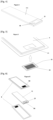
- each of the tabs 21 and their respective junctions with the body of the cell 1 matches the external surface 111, 112 of the cell 1 so as to limit the presence of roughness or surface variations likely to increase the risk of tearing or degradation of the tab 21 relative to the rest of the structure of the cell 1.
- the folding of the respective tabs 21 of the positive electrodes and negative at the level of different and opposite surfaces 111, 112 of the pocket 11 of cell 1 in particular authorizes a series assembly of several homologous cells 1 according to the invention juxtaposed.
- the folding of the flat tabs 21 against the external surfaces 111, 112 of the pocket 11 of cell 1 makes it possible to restrict or even eliminate the portion dedicated to the tabs in the length of cell 1.
- the cell 1 of the invention is able to comprise a body whose external surface is made by the pocket 11 which has a greater length, so as to occupy the space left vacant by the different folded tabs 21.
- the folding of tabs 21 against the external surfaces 111, 112 of the pocket 11 authorize the construction of cells 1 in which the part intended for the storage of electrical energy is more important than in the cells of the prior art, while allowing the installation of these cells 11 with greater storage capacity in existing accumulator blocks 9.
- the different electrodes 2 and separator films 3 planes are likely to correspond to electrodes 2 and separator films 3 of known type.
- the electrodes 2 are thus likely to be made, for example, based on graphite for the negative polarity electrode and based on a lithium manganese and cobalt nickel oxide for the positive polarity electrode.
- these electrodes 2 are likely to be associated with one or more liquid or solid electrolytes, inside the cell 1.
- At least one insulator 4 is placed between the contact tabs 21 of folded electrodes 2 and the corresponding surfaces 111, 112 of the pouch 11.
- This insulator 4 provides an interface between the surface of the tongue 21 and the corresponding surface 111, 112 of the pocket 11, so as to avoid a parasitic electrical connection between the tongue 21 and the surface 111, 112 of the pocket 11.
- This insulator 4 thus has a surface of dimensions at least greater than the dimensions of the surface of the folded tongue 21 capable of bearing against the corresponding surface 111, 112 of the pocket 11.
- this insulator 4 is capable of being made of polymer, Teflon, acrylonitrile butadiene styrene also called ABS.
- the electrodes 2 have substantially rectilinear and similar planar shapes with respective contact tabs 21 at the end so that, in the arrangement of electrodes 2 and separator films 3, the contact tab 21 of the positive electrodes 2 is positioned at an end opposite that of the contact tab 21 of the negative electrodes 2.
- the positioning of the contact tabs 21 at the respective ends and surfaces of the cell 1 authorizes a head-to-tail installation of homologous cells 1 according to the invention juxtaposed so that these cells 1 make a connection electrical via one of their tabs 21.
- This arrangement of the contact tabs 21 at different ends of the cell 1 also allows a juxtaposition of several cells 1 according to an electrical assembly in series inside an accumulator block 9 without a fan distribution phenomenon occurring due to the positioning of the contact tabs 21 at the same end of cell 1.
- the cell 1 also comprises a waterproof envelope 5 inside which the pocket 11 is housed, so that at at least one of its faces, the envelope 5 comprises an orifice 51 closed by a conductive contact interface 52, possibly in association with an insulating frame 53, this orifice 51 and the conductive contact interface 52 being arranged opposite folded contact tabs 21 of respective electrodes 2.
- the orifice 51 is heat sealed at its peripheral edge with the conductive contact interface 52.
- the junction between the edge of the orifice 51 and the conductive contact interface 52 involves an insulating frame 53 made of a suitable material to avoid any parasitic electrical conduction between the conductive contact interface 52 and the surface of the envelope 5.
- the insulating frame 53 on the one hand, is positioned and sealed along the entire interior edge of the orifice 51 of the envelope 5 and, on the other hand, sealingly surrounds the periphery of the conductive contact interface 52.
- the interior surface of the conductive contact interface 52 is arranged to be in electrical contact with one of the two negative or positive electrode contact tabs 21 of cell 1.
- the envelope 5 of cell 1 comprises two orifices 51 respectively positioned at opposite surfaces so that the conductive contact interfaces 52 associated with each of these orifices are positioned opposite a respective electrode contact tongue 21 with which an electrical contact is made, so that the exterior surface of each conductive contact interface 52 forms the electrical contact surface, negative or positive, of the cell 1 with an element exterior to the envelope 5.
- the elements positioned at the interior of the envelope 5 thus makes no direct contact with the exterior elements.
- the electrical contacts between the positive and negative electrodes 2 of the cell 1 and the exterior are made via the pair of tabs 21 respectively associated with a conductive contact interface 52.
- the envelope 5 remains completely waterproof while allowing electrical exchanges with the outside at the level of the pair of orifices 51 associated with the respective conductive contact interfaces 52.
- the electrical connection between two juxtaposed cells 1 takes place via these conductive contact interfaces 52 carried by respective cells 1 and positioned opposite each other.
- the conductive contact interface 52 which closes the orifice 51 of the envelope 5 comprises an arrangement comprising a relief having a height greater than the thickness of the envelope 5 so as to be able to cooperate with a conductive contact interface 52 carried by a juxtaposed homologous cell 1.
- the electrical conduction between a tab 21 for contacting electrodes 2 and the exterior must be carried out through the thickness of the envelope 5 at the level of the orifices 51.
- the effective thickness of the conductive contact interface 52 positioned at the level of the orifices 51 is greater than the thickness of the envelope 5.
- At least one of the surfaces of the conductive contact interface 52 comprises a relief, in particular the surface of the conductive contact interface 52 whose periphery is fixed to the orifice 51 of the envelope 5. This relief then has a height or thickness adapted to pass through the orifice 51 of the envelope 5 and thus allow effective electrical contact which is able to overcome the thickness of the envelope 5.
- the cell 1 comprises at least one contact reinforcement 54 fixed to one of the contact tabs 21 of folded electrodes and capable of cooperating with the interior surface of a conductive contact interface 52 fixed to the envelope 5.
- This contact reinforcement 54 is made of a conductive material so as not to limit the electrical exchanges between the tongue 21 and the interface conductive contact.
- this contact reinforcement 54 has greater rigidity than that of a tongue 21 so as to be able to withstand possible mechanical forces under the effect of pressure exerted through the conductive contact interface 52, while preventing the electrode contact tab 21 2 from being subject to any degradation resulting from these mechanical forces.
- the reinforcement 54 is thus fixed on the surface of the corresponding contact tab 21 prior to positioning the association of electrodes 2 and separator films 3 inside the envelope 5 of the cell 1.
- the envelope 5 is produced by cooperation of two half-shells assembled together by welding on their periphery.
- the envelope 5 having a substantially planar arrangement, each of the half-shells also has a substantially planar arrangement and integrates an orifice 51 associated with a conductive contact interface 52 possibly in association with an insulating frame 53.
- the invention also relates to an accumulator block 9 comprising a casing 91, characterized in that the accumulator block 9 comprises at least two cells 1 according to the invention housed inside the casing 91 so as to be juxtaposed parallel to each other and maintained in compression, so that, on the one hand, the tongue 21 of folded contact of the positive electrodes 2 of a first cell 1 are in electrical contact with a positive terminal block 92 and that, on the other hand, the folded contact tab 21 of the negative electrodes 2 of a second cell 1 are in electrical contact with a negative terminal block 92, the at least two cells 1 being connected in series between the two terminal blocks 92, positive and negative, of the accumulator block 9.
- the casing 91 of the accumulator block 9 can be constructed under the shape of two halves of casing 91 which, once assembled, provide the housing for receiving the at least two cells 1. Maintaining the cells 1 in compression inside the casing 91 of the accumulator block 9 involves elastic means specifically intended to maintain the position of the cells 1 pressing against each other and in electrical contact, in particular at the level of their conductive contact interfaces 52. These elastic means are likely to correspond to compression plates 94 associated with spring elements which carry out clamping by pinching the cells 1 juxtaposed in contact with each other by their main surfaces.
- the cells 1 having substantially planar arrangements, these cells 1 are juxtaposed inside the casing 91 while being supported by their surfaces, so that, by compression, the folded contact tab 21 of the positive electrodes 2 of a cell 1 is in electrical contact with the folded contact tab 21 of the negative electrodes 2 of another juxtaposed cell 1.
- connection bar is positioned as an intermediate contactor at the level of the electrical junction between the folded contact tab 21 of the positive electrodes 2 of a cell 1 and the folded contact tab 21 of the negative electrodes 2 of another cell 1 juxtaposed and connected in series with the first cell 1.
- This connection bar is thus capable of mechanically and electrically optimizing the junction between the least two cells 1 juxtaposed.
- the connection bar is capable of allowing an electrical connection between, on the one hand, the contact tabs 21 of the identical electrodes 2, positive or negative, respective of several cells 1 and, on the other hand, the contact tab 21 of the opposite electrodes 2 of another juxtaposed cell 1.
- the cells 1 having substantially planar arrangements, these cells 1 grouped inside the casing 91 of the accumulator block 9 in juxtaposed sets 12, the cells 1 being supported by their respective conductive contact interfaces 52 inside each set 12 and connected in series, so that the contact tab 21 of the positive electrodes 2 of a cell 1 are in electrical contact with the contact tab 21 of the negative electrodes of another juxtaposed cell 1, at least one connection bar being positioned as an intermediate contactor between two pairs of cells 1 respectively arranged in two juxtaposed sets 12.
- Such a connection bar thus makes it possible to operate a parallel connection of several cells 1 positioned inside the casing 92 of the accumulator block 9.
- the two juxtaposed sets 12 thus relate to two groupings of cells 1 arranged in compression parallel between them.
Landscapes
- Chemical & Material Sciences (AREA)
- Chemical Kinetics & Catalysis (AREA)
- Electrochemistry (AREA)
- General Chemical & Material Sciences (AREA)
- Engineering & Computer Science (AREA)
- Manufacturing & Machinery (AREA)
- Aviation & Aerospace Engineering (AREA)
- Secondary Cells (AREA)
Applications Claiming Priority (1)
| Application Number | Priority Date | Filing Date | Title |
|---|---|---|---|
| FR2212683A FR3142840B1 (fr) | 2022-12-02 | 2022-12-02 | Cellule pour accumulateur à arrangement optimisé |
Publications (1)
| Publication Number | Publication Date |
|---|---|
| EP4391131A1 true EP4391131A1 (de) | 2024-06-26 |
Family
ID=85569565
Family Applications (1)
| Application Number | Title | Priority Date | Filing Date |
|---|---|---|---|
| EP23214075.6A Pending EP4391131A1 (de) | 2022-12-02 | 2023-12-04 | Batteriezelle mit optimierter anordnung |
Country Status (2)
| Country | Link |
|---|---|
| EP (1) | EP4391131A1 (de) |
| FR (1) | FR3142840B1 (de) |
Citations (5)
| Publication number | Priority date | Publication date | Assignee | Title |
|---|---|---|---|---|
| US20040038124A1 (en) * | 2002-08-22 | 2004-02-26 | Nissan Motor Co., Ltd | Laminate cell, assembled battery, battery module and electric vehicle |
| US20140370367A1 (en) * | 2013-06-18 | 2014-12-18 | Denso Corporation | Structure of battery unit |
| US20170077466A1 (en) * | 2015-09-16 | 2017-03-16 | Hyundai Mobis Co., Ltd. | High voltage battery submodule |
| CN108417752A (zh) * | 2018-05-02 | 2018-08-17 | 杭州泓创新能源有限公司 | 电池组组成结构及其连接方法 |
| EP4040572A1 (de) * | 2021-02-08 | 2022-08-10 | Prime Planet Energy & Solutions, Inc. | Batteriepack |
-
2022
- 2022-12-02 FR FR2212683A patent/FR3142840B1/fr active Active
-
2023
- 2023-12-04 EP EP23214075.6A patent/EP4391131A1/de active Pending
Patent Citations (5)
| Publication number | Priority date | Publication date | Assignee | Title |
|---|---|---|---|---|
| US20040038124A1 (en) * | 2002-08-22 | 2004-02-26 | Nissan Motor Co., Ltd | Laminate cell, assembled battery, battery module and electric vehicle |
| US20140370367A1 (en) * | 2013-06-18 | 2014-12-18 | Denso Corporation | Structure of battery unit |
| US20170077466A1 (en) * | 2015-09-16 | 2017-03-16 | Hyundai Mobis Co., Ltd. | High voltage battery submodule |
| CN108417752A (zh) * | 2018-05-02 | 2018-08-17 | 杭州泓创新能源有限公司 | 电池组组成结构及其连接方法 |
| EP4040572A1 (de) * | 2021-02-08 | 2022-08-10 | Prime Planet Energy & Solutions, Inc. | Batteriepack |
Also Published As
| Publication number | Publication date |
|---|---|
| FR3142840B1 (fr) | 2025-07-18 |
| FR3142840A1 (fr) | 2024-06-07 |
Similar Documents
| Publication | Publication Date | Title |
|---|---|---|
| CA2697231C (fr) | Batterie constituee d'une pluralite de cellules positionnees et reliees entre elles, sans soudure | |
| FR2996063A1 (fr) | Element de stockage electrique | |
| FR2752089A1 (fr) | Generateur electrochimique cylindrique | |
| FR3007896A1 (fr) | Module de batterie pour vehicule electrique ou hybride integrant un echangeur de chaleur | |
| EP3523837B1 (de) | Akkumulator | |
| EP3020081B1 (de) | Modul mit mehreren entfernbaren zellen, batterie mit solch einem modul und fahrzeug mit solch einer batterie | |
| EP2564450B1 (de) | Akkumulatoranordnung für eine batterie eines elektro- oder hybridfahrzeuges mit verformbarer verbinderstütze | |
| EP2564451B1 (de) | Batterieeinheit für ein elektro- oder hybridfahrzeug | |
| EP2557579B1 (de) | Superkondensatorzelle und superkapazitives Modul, das mit mehreren solchen Zellen ausgestattet ist | |
| EP4391131A1 (de) | Batteriezelle mit optimierter anordnung | |
| FR2692077A1 (fr) | Accumulateurs à électrodes bipolaires. | |
| EP3809488A1 (de) | Dummy-batterie | |
| EP4162564A1 (de) | Verbindungselement zum verbinden zweier akkumulatoren | |
| WO2022243243A1 (fr) | Elément électrochimique pour batterie, et batterie correspondante | |
| EP4677673A1 (de) | Batteriezellenblock, insbesondere für ein kraftfahrzeug | |
| EP4078714A1 (de) | Elektrochemische zelle mit dreidimensionaler elektrodenstruktur | |
| EP4604261A1 (de) | Batteriezelle und anordnung solcher zellen | |
| EP4604233A1 (de) | Zellengehäuseschaufel, gehäuse dafür, batteriezelle mit solch einer gehäuseschale und anordnung solcher zellen | |
| FR3153470A1 (fr) | Ensemble comprenant un élément électrochimique et un élément électrique rechargeable et procédé de fabrication associé | |
| FR3143215A1 (fr) | Module de batterie ou pack-batterie, comprenant une pluralité d’accumulateurs de format cylindrique agencés en parallèles les uns aux autres, assemblés par emmanchement dans un flasque de bridage supportant les busbars des bornes de sortie des accumulateurs. | |
| EP4604232A1 (de) | Zellengehäuse, batteriezelle mit einem solchen zellengehäuse und anordnung solcher zellen | |
| FR3152654A1 (fr) | Cellule de batterie cylindrique et son procédé de fabrication | |
| FR3158386A1 (fr) | Dispositif de stockage d’énergie électrique, notamment pour motorisation électrique d’un véhicule automobile | |
| FR3165360A1 (fr) | Cellule électrochimique et module de batterie comprenant de telles cellules électrochimiques | |
| FR3143214A1 (fr) | Module de batterie ou pack-batterie, comprenant une matrice à accumulateurs de format cylindrique, logée et bridée dans un boitier périphérique. |
Legal Events
| Date | Code | Title | Description |
|---|---|---|---|
| PUAI | Public reference made under article 153(3) epc to a published international application that has entered the european phase |
Free format text: ORIGINAL CODE: 0009012 |
|
| STAA | Information on the status of an ep patent application or granted ep patent |
Free format text: STATUS: THE APPLICATION HAS BEEN PUBLISHED |
|
| AK | Designated contracting states |
Kind code of ref document: A1 Designated state(s): AL AT BE BG CH CY CZ DE DK EE ES FI FR GB GR HR HU IE IS IT LI LT LU LV MC ME MK MT NL NO PL PT RO RS SE SI SK SM TR |
|
| STAA | Information on the status of an ep patent application or granted ep patent |
Free format text: STATUS: REQUEST FOR EXAMINATION WAS MADE |
|
| 17P | Request for examination filed |
Effective date: 20241220 |