EP4391205A1 - Feuille d'électrode, ensemble électrode, élément de batterie, batterie et dispositif électrique - Google Patents
Feuille d'électrode, ensemble électrode, élément de batterie, batterie et dispositif électrique Download PDFInfo
- Publication number
- EP4391205A1 EP4391205A1 EP23844162.0A EP23844162A EP4391205A1 EP 4391205 A1 EP4391205 A1 EP 4391205A1 EP 23844162 A EP23844162 A EP 23844162A EP 4391205 A1 EP4391205 A1 EP 4391205A1
- Authority
- EP
- European Patent Office
- Prior art keywords
- battery
- tab portion
- welded zone
- tab
- body portion
- Prior art date
- Legal status (The legal status is an assumption and is not a legal conclusion. Google has not performed a legal analysis and makes no representation as to the accuracy of the status listed.)
- Pending
Links
Images


Classifications
-
- H—ELECTRICITY
- H01—ELECTRIC ELEMENTS
- H01M—PROCESSES OR MEANS, e.g. BATTERIES, FOR THE DIRECT CONVERSION OF CHEMICAL ENERGY INTO ELECTRICAL ENERGY
- H01M50/00—Constructional details or processes of manufacture of the non-active parts of electrochemical cells other than fuel cells, e.g. hybrid cells
- H01M50/50—Current conducting connections for cells or batteries
- H01M50/531—Electrode connections inside a battery casing
-
- H—ELECTRICITY
- H01—ELECTRIC ELEMENTS
- H01M—PROCESSES OR MEANS, e.g. BATTERIES, FOR THE DIRECT CONVERSION OF CHEMICAL ENERGY INTO ELECTRICAL ENERGY
- H01M10/00—Secondary cells; Manufacture thereof
- H01M10/05—Accumulators with non-aqueous electrolyte
- H01M10/052—Li-accumulators
-
- H—ELECTRICITY
- H01—ELECTRIC ELEMENTS
- H01M—PROCESSES OR MEANS, e.g. BATTERIES, FOR THE DIRECT CONVERSION OF CHEMICAL ENERGY INTO ELECTRICAL ENERGY
- H01M10/00—Secondary cells; Manufacture thereof
- H01M10/05—Accumulators with non-aqueous electrolyte
- H01M10/052—Li-accumulators
- H01M10/0525—Rocking-chair batteries, i.e. batteries with lithium insertion or intercalation in both electrodes; Lithium-ion batteries
-
- H—ELECTRICITY
- H01—ELECTRIC ELEMENTS
- H01M—PROCESSES OR MEANS, e.g. BATTERIES, FOR THE DIRECT CONVERSION OF CHEMICAL ENERGY INTO ELECTRICAL ENERGY
- H01M10/00—Secondary cells; Manufacture thereof
- H01M10/05—Accumulators with non-aqueous electrolyte
- H01M10/054—Accumulators with insertion or intercalation of metals other than lithium, e.g. with magnesium or aluminium
-
- H—ELECTRICITY
- H01—ELECTRIC ELEMENTS
- H01M—PROCESSES OR MEANS, e.g. BATTERIES, FOR THE DIRECT CONVERSION OF CHEMICAL ENERGY INTO ELECTRICAL ENERGY
- H01M10/00—Secondary cells; Manufacture thereof
- H01M10/05—Accumulators with non-aqueous electrolyte
- H01M10/058—Construction or manufacture
- H01M10/0587—Construction or manufacture of accumulators having only wound construction elements, i.e. wound positive electrodes, wound negative electrodes and wound separators
-
- H—ELECTRICITY
- H01—ELECTRIC ELEMENTS
- H01M—PROCESSES OR MEANS, e.g. BATTERIES, FOR THE DIRECT CONVERSION OF CHEMICAL ENERGY INTO ELECTRICAL ENERGY
- H01M4/00—Electrodes
- H01M4/02—Electrodes composed of, or comprising, active material
- H01M4/13—Electrodes for accumulators with non-aqueous electrolyte, e.g. for lithium-accumulators; Processes of manufacture thereof
-
- H—ELECTRICITY
- H01—ELECTRIC ELEMENTS
- H01M—PROCESSES OR MEANS, e.g. BATTERIES, FOR THE DIRECT CONVERSION OF CHEMICAL ENERGY INTO ELECTRICAL ENERGY
- H01M4/00—Electrodes
- H01M4/02—Electrodes composed of, or comprising, active material
- H01M4/64—Carriers or collectors
- H01M4/66—Selection of materials
- H01M4/665—Composites
- H01M4/667—Composites in the form of layers, e.g. coatings
-
- H—ELECTRICITY
- H01—ELECTRIC ELEMENTS
- H01M—PROCESSES OR MEANS, e.g. BATTERIES, FOR THE DIRECT CONVERSION OF CHEMICAL ENERGY INTO ELECTRICAL ENERGY
- H01M50/00—Constructional details or processes of manufacture of the non-active parts of electrochemical cells other than fuel cells, e.g. hybrid cells
- H01M50/10—Primary casings; Jackets or wrappings
- H01M50/102—Primary casings; Jackets or wrappings characterised by their shape or physical structure
- H01M50/103—Primary casings; Jackets or wrappings characterised by their shape or physical structure prismatic or rectangular
-
- H—ELECTRICITY
- H01—ELECTRIC ELEMENTS
- H01M—PROCESSES OR MEANS, e.g. BATTERIES, FOR THE DIRECT CONVERSION OF CHEMICAL ENERGY INTO ELECTRICAL ENERGY
- H01M50/00—Constructional details or processes of manufacture of the non-active parts of electrochemical cells other than fuel cells, e.g. hybrid cells
- H01M50/10—Primary casings; Jackets or wrappings
- H01M50/147—Lids or covers
- H01M50/148—Lids or covers characterised by their shape
- H01M50/15—Lids or covers characterised by their shape for prismatic or rectangular cells
-
- H—ELECTRICITY
- H01—ELECTRIC ELEMENTS
- H01M—PROCESSES OR MEANS, e.g. BATTERIES, FOR THE DIRECT CONVERSION OF CHEMICAL ENERGY INTO ELECTRICAL ENERGY
- H01M50/00—Constructional details or processes of manufacture of the non-active parts of electrochemical cells other than fuel cells, e.g. hybrid cells
- H01M50/40—Separators; Membranes; Diaphragms; Spacing elements inside cells
- H01M50/471—Spacing elements inside cells other than separators, membranes or diaphragms; Manufacturing processes thereof
- H01M50/474—Spacing elements inside cells other than separators, membranes or diaphragms; Manufacturing processes thereof characterised by their position inside the cells
-
- H—ELECTRICITY
- H01—ELECTRIC ELEMENTS
- H01M—PROCESSES OR MEANS, e.g. BATTERIES, FOR THE DIRECT CONVERSION OF CHEMICAL ENERGY INTO ELECTRICAL ENERGY
- H01M50/00—Constructional details or processes of manufacture of the non-active parts of electrochemical cells other than fuel cells, e.g. hybrid cells
- H01M50/50—Current conducting connections for cells or batteries
- H01M50/531—Electrode connections inside a battery casing
- H01M50/533—Electrode connections inside a battery casing characterised by the shape of the leads or tabs
-
- H—ELECTRICITY
- H01—ELECTRIC ELEMENTS
- H01M—PROCESSES OR MEANS, e.g. BATTERIES, FOR THE DIRECT CONVERSION OF CHEMICAL ENERGY INTO ELECTRICAL ENERGY
- H01M50/00—Constructional details or processes of manufacture of the non-active parts of electrochemical cells other than fuel cells, e.g. hybrid cells
- H01M50/50—Current conducting connections for cells or batteries
- H01M50/531—Electrode connections inside a battery casing
- H01M50/534—Electrode connections inside a battery casing characterised by the material of the leads or tabs
-
- H—ELECTRICITY
- H01—ELECTRIC ELEMENTS
- H01M—PROCESSES OR MEANS, e.g. BATTERIES, FOR THE DIRECT CONVERSION OF CHEMICAL ENERGY INTO ELECTRICAL ENERGY
- H01M50/00—Constructional details or processes of manufacture of the non-active parts of electrochemical cells other than fuel cells, e.g. hybrid cells
- H01M50/50—Current conducting connections for cells or batteries
- H01M50/531—Electrode connections inside a battery casing
- H01M50/536—Electrode connections inside a battery casing characterised by the method of fixing the leads to the electrodes, e.g. by welding
-
- H—ELECTRICITY
- H01—ELECTRIC ELEMENTS
- H01M—PROCESSES OR MEANS, e.g. BATTERIES, FOR THE DIRECT CONVERSION OF CHEMICAL ENERGY INTO ELECTRICAL ENERGY
- H01M50/00—Constructional details or processes of manufacture of the non-active parts of electrochemical cells other than fuel cells, e.g. hybrid cells
- H01M50/50—Current conducting connections for cells or batteries
- H01M50/572—Means for preventing undesired use or discharge
- H01M50/584—Means for preventing undesired use or discharge for preventing incorrect connections inside or outside the batteries
- H01M50/586—Means for preventing undesired use or discharge for preventing incorrect connections inside or outside the batteries inside the batteries, e.g. incorrect connections of electrodes
-
- H—ELECTRICITY
- H01—ELECTRIC ELEMENTS
- H01M—PROCESSES OR MEANS, e.g. BATTERIES, FOR THE DIRECT CONVERSION OF CHEMICAL ENERGY INTO ELECTRICAL ENERGY
- H01M50/00—Constructional details or processes of manufacture of the non-active parts of electrochemical cells other than fuel cells, e.g. hybrid cells
- H01M50/50—Current conducting connections for cells or batteries
- H01M50/572—Means for preventing undesired use or discharge
- H01M50/584—Means for preventing undesired use or discharge for preventing incorrect connections inside or outside the batteries
- H01M50/59—Means for preventing undesired use or discharge for preventing incorrect connections inside or outside the batteries characterised by the protection means
- H01M50/595—Tapes
-
- H—ELECTRICITY
- H01—ELECTRIC ELEMENTS
- H01M—PROCESSES OR MEANS, e.g. BATTERIES, FOR THE DIRECT CONVERSION OF CHEMICAL ENERGY INTO ELECTRICAL ENERGY
- H01M2220/00—Batteries for particular applications
- H01M2220/20—Batteries in motive systems, e.g. vehicle, ship, plane
-
- Y—GENERAL TAGGING OF NEW TECHNOLOGICAL DEVELOPMENTS; GENERAL TAGGING OF CROSS-SECTIONAL TECHNOLOGIES SPANNING OVER SEVERAL SECTIONS OF THE IPC; TECHNICAL SUBJECTS COVERED BY FORMER USPC CROSS-REFERENCE ART COLLECTIONS [XRACs] AND DIGESTS
- Y02—TECHNOLOGIES OR APPLICATIONS FOR MITIGATION OR ADAPTATION AGAINST CLIMATE CHANGE
- Y02E—REDUCTION OF GREENHOUSE GAS [GHG] EMISSIONS, RELATED TO ENERGY GENERATION, TRANSMISSION OR DISTRIBUTION
- Y02E60/00—Enabling technologies; Technologies with a potential or indirect contribution to GHG emissions mitigation
- Y02E60/10—Energy storage using batteries
Definitions
- This application relates to the field of battery technologies, and in particular, to an electrode plate, an electrode assembly, a battery cell, a battery, and an electric device.
- Embodiments of this application provide an electrode plate, an electrode assembly, a battery cell, a battery, and an electric device, which can reduce the probability of safety issues in battery production.
- an electrode plate including: a current collector, where the current collector includes an insulation layer and a conductive layer disposed on an outer surface of the insulation layer, and the conductive layer includes a body portion and a tab portion arranged along a first direction; and a conductive structure, where the conductive structure is welded to the tab portion to form a welded zone, the conductive structure extends in a direction leaving the body portion, and in a second direction, a size Li of an end of the welded zone near the body portion is greater than a preset threshold, where the preset threshold is inversely related to the thickness of the tab portion in a third direction, and the second direction is perpendicular to the first direction and parallel to the tab portion, where the third direction is perpendicular to the first direction and the second direction.
- the electrode plate includes the current collector and the conductive structure.
- the current collector includes the insulation layer and the conductive layer disposed on the outer surface of the insulation layer.
- the conductive layer includes the body portion and the tab portion disposed along the first direction.
- the conductive structure is welded to the tab portion to form the welded zone, and the size L 1 of the end of the welded zone near the body portion in the second direction is greater than a preset threshold.
- the preset threshold is inversely related to the thickness of the tab portion in the third direction.
- the conductive structure with sufficient current flow capacity is welded to the tab portion, allowing the current to flow from the body portion through the tab portion (a portion near the body portion and not welded to the conductive structure) to the welded zone and then to the conductive structure, thus providing sufficient current flow capacity.
- the end of the welded zone near the body portion is the starting end where the conductive structure is connected to the tab portion.
- the current flow capacity at this location is also affected by the current flow capacity of the tab portion. In addition, this location is the end portion of the welded zone.
- a size L 1 of the end of the welded zone near the body portion in the second direction is set greater than a preset threshold, and the preset threshold is inversely related to the thickness of the tab portion in the third direction. This reduces the possibility of the end portion of the welded zone near the body portion being fused due to insufficient current flow capacity when a short circuit occurs in the battery, thereby reducing the possibility of sparks occurring in the end portion of the welded zone near the body portion and reducing the probability of safety issues in battery production.
- the preset threshold is L 2 ⁇ H 2 H 1 ⁇ C ⁇ A , where H 2 indicates thickness of an adapter piece at a minimum current flow width thereof, L 2 indicates total width of connection surfaces between the conductive structure and the adapter piece at the minimum current flow width in the width direction of the adapter piece, H 1 indicates the thickness of the tab portion in the third direction, C indicates the number of conductive structures connected to one adapter piece, and A is a constant not less than 1.
- the size L 1 of the end portion of the welded zone near the body portion in the second direction needs to be greater than the preset threshold L 2 ⁇ H 2 H 1 ⁇ C ⁇ A , so that the total current flow area of the end portion of the welded zone near the body portion, formed on multiple conductive structures, is greater than the current flow area of the corresponding adapter piece connected to the multiple conductive structures.
- constant A 1 ⁇ A ⁇ 2.
- the size L 1 of the end portion of the welded zone should not be excessively large, so as to prevent lower plastics beneath the end cover from compressing the conductive structure. Therefore, the value of the constant A should not be excessively large, and the range of the constant A is 1 to 2.
- the tab portion includes a first tab portion and a second tab portion, where in the first direction, the first tab portion is disposed between the body portion and the second tab portion, and in the second direction, a size of the first tab portion is greater than a size of the second tab portion.
- the size of the first tab portion is greater than the size of the second tab portion in the second direction, that is, the first tab portion connected to the body portion has a relatively large size in the second direction. This can increase the contact area between the body portion and the tab portion, thereby increasing the connection strength, while the second tab portion has a relatively small size, which can reduce overall space occupied by the tab portion.
- the welded zone includes a first welded zone and a second welded zone, where the first welded zone is located at the first tab portion, the second welded zone is located at the second tab portion, and in the second direction, a size of the first welded zone is greater than a size of the second welded zone.
- the second welded zone is located at the second tab portion, which has a larger size in the second direction, so that the size L 1 of the end portion of the welded zone near the body portion in the second direction is greater than the preset threshold, where the welded zone is formed during the tab portion is welded to the conductive structure.
- the current flow area of the end portion of the welded zone near the body portion is relatively large. This reduces the possibility of the end portion of the welded zone near the body portion being fused due to insufficient current flow capacity when a short circuit occurs in the battery, thereby reducing the probability of safety issues in battery production.
- the welding area between the second welded zone and the second tab portion is relatively large, which can improve the connection strength between them.
- a protective layer is provided on a portion of an outer surface of the tab portion.
- the protective layer is provided between the conductive structure and an active substance layer on an outer surface of the body portion, providing support to the tab portion and preventing deformation of the tab portion from affecting the current flow capacity of the electrode plate.
- the protective layer is made of an insulation material to prevent the protective layer from conducting and affecting the current flow path in the electrode plate, ensuring electrical connection safety of the electrode plate.
- an electrode assembly including: the electrode plate according to the foregoing first aspect or any possible implementation of the first aspect.
- a battery cell including: the foregoing electrode assembly according to the second aspect or any possible embodiment of the second aspect, and a housing configured to accommodate the electrode assembly.
- the housing has an opening
- the battery cell further includes an end cover, where the end cover is configured to close the opening.
- a battery including: the foregoing battery cell according to the third aspect or any possible embodiment of the third aspect.
- an electric device including: the battery according to the fourth aspect or any possible embodiment of the fifth aspect, where the battery is configured to supply electrical energy.
- the electrode plate includes a current collector and a conductive structure.
- the current collector includes an insulation layer and a conductive layer disposed on the outer surface of the insulation layer.
- the conductive layer includes a body portion and a tab portion disposed along a first direction.
- the conductive structure is welded to the tab portion, and a size L 1 of the end of the welded zone near the body portion in the second direction is greater than a preset threshold.
- the preset threshold is inversely related to the thickness of the tab portion in the third direction.
- a conductive structure with sufficient current flow capacity is connected to the tab portion by welding, allowing the current to flow from the body portion through the tab portion (a portion near the body portion and not welded to the conductive structure) to the welded zone and then to the conductive structure, thus having sufficient current flow capacity.
- the end of the welded zone near the body portion is the starting end where the conductive structure is connected to the tab portion.
- the current flow capacity at this location is also affected by the current flow capacity of the tab portion. In addition, this location is the end portion of the welded zone.
- a size L 1 of the end of the welded zone near the body portion in the second direction is set greater than a preset threshold, and the preset threshold is inversely related to the thickness of the tab portion in the third direction. This reduces the possibility of the end portion of the welded zone near the body portion being fused due to insufficient current flow capacity when a short circuit occurs in the battery, thereby reducing the possibility of sparks occurring in the end portion of the welded zone near the body portion and reducing the probability of safety issues in battery.
- the battery cell may include a lithium-ion secondary battery, a lithium-ion primary battery, a lithium-sulfur battery, a sodium-lithium-ion battery, a sodium-ion battery, a magnesium-ion battery, or the like. This is not limited in the embodiments of this application.
- the battery cell may be cylindrical, flat, cuboid, or of other shapes, which is not limited in the embodiments of this application either. Battery cells are typically divided into three types by a packaging method: cylindrical cell, prismatic cell, and pouch cell. The type of battery is not limited in the embodiments of this application either.
- the battery mentioned in the embodiments of this application is a single physical module that includes one or more battery cells for providing a higher voltage and capacity.
- the battery mentioned in this application may include a battery module, a battery pack, or the like.
- a battery typically includes a box configured to enclose one or more battery cells. The box can prevent liquids or other foreign matter from affecting charging or discharging of the battery cell.
- the battery cell may include an electrode assembly and an electrolyte.
- the electrode assembly includes a positive electrode plate, a negative electrode plate, and a separator.
- the battery cell functions mainly rely on the migration of metal ions between the positive electrode plate and the negative electrode plate.
- the positive electrode plate includes a positive electrode current collector and a positive electrode active substance layer.
- the positive electrode active substance layer is applied on a surface of the positive electrode current collector. A current collector uncoated with the positive electrode active substance layer bulges out of a current collector coated with the positive electrode active substance layer, and the current collector uncoated with the positive electrode active substance layer is used as a positive electrode tab.
- a lithium-ion battery is used as an example, for which, the positive electrode current collector may be made of aluminum and the positive electrode active substance may be lithium cobaltate, lithium iron phosphate, ternary lithium, lithium manganate, or the like.
- the negative electrode plate includes a negative electrode current collector and a negative electrode active substance layer. The negative electrode active substance layer is applied on a surface of the negative electrode current collector. A current collector uncoated with the negative electrode active substance layer protrudes from the current collector coated with the negative electrode active substance layer and the current collector uncoated with the negative electrode active substance layer is used as a negative electrode tab.
- the negative electrode current collector may be made of copper, and the negative electrode active substance may be carbon, silicon, or the like.
- the separator may be made of polypropylene (PP), polyethylene (PE), or the like.
- the electrode assembly may be a wound structure or a stacked structure. This is not limited in the embodiments of this application.
- Electric vehicle batteries have been not only used in energy storage power supply systems such as hydroelectric power plants, thermal power plants, wind power plants, and solar power plants, but also widely used in many other fields including electric transportation tools such as electric bicycles, electric motorcycles, and electric vehicles, military equipment, and aerospace. With the continuous expansion of application fields of electric vehicle batteries, market demands for electric vehicle batteries are also increasing.
- performance parameters such as energy density, cycle life, discharge capacity, and charge and discharge rate, as well as safety of the battery.
- a composite current collector that is, the current collector includes an insulation material and a metal conductive layer coated on surface of the insulation material.
- thickness of the metal conductive layer is also reduced, reducing the risk of burrs on the metal conductive layer piercing the separator.
- less thickness of the metal conductive layer in the composite current collector leads to insufficient current flow capacity of the tab, affecting safety performance of the battery. Therefore, how the current flow capacity of the tab is improved and thereby reducing the probability of safety issues in battery production is an urgent problem that needs to be solved.
- the embodiments of this application provide an electrode plate, where the electrode plate includes a current collector and a conductive structure.
- the current collector includes an insulation layer and a conductive layer disposed on the outer surface of the insulation layer.
- the conductive layer includes a body portion and a tab portion disposed along a first direction.
- the conductive structure is welded to the tab portion to form the welded zone, and a size L 1 of the end of the welded zone near the body portion in the second direction is greater than a preset threshold.
- the preset threshold is inversely related to the thickness of the tab portion in the third direction.
- a conductive structure with sufficient current flow capacity is connected to the tab portion by welding, allowing the current to flow from the body portion through the tab portion (a portion near the body portion and not welded to the conductive structure) to the welded zone and then to the conductive structure.
- the size L 1 of the end of the welded zone near the body portion in the second direction is greater than a preset threshold to reduce the possibility of an end portion of the welded zone near the body portion being fused due to insufficient current flow capacity when a short circuit occurs in the battery, thereby reducing the possibility of sparks occurring at the end portion of the welded zone near the body portion and reducing the probability of safety issues in battery production.
- batteries for example, mobile phones, portable devices, notebook computers, electric bicycles, electric toys, electric tools, electric vehicles, ships, and spacecrafts.
- spacecrafts include airplanes, rockets, space shuttles, and spaceships.
- FIG. 1 is a structural schematic diagram of a vehicle 1 according to an embodiment of this application.
- the vehicle 1 may be a fuel vehicle, a gas vehicle, or a new energy vehicle, and the new energy vehicle may be a battery electric vehicle, a hybrid electric vehicle, an extended range electric vehicle, or the like.
- a motor 40, a controller 30, and a battery 10 may be provided inside the vehicle 1, where the controller 30 is configured to control the battery 10 to supply power to the motor 40.
- the battery 10 may be disposed at the bottom, front, or rear of the vehicle 1.
- the battery 10 may be configured to supply power to the vehicle 1.
- the battery 10 may be used as an operational power source for the vehicle 1 that is configured for a circuit system of the vehicle 1, for example, to satisfy power needs of start, navigation, and running of the vehicle 1.
- the battery 10 can be used not only as the operational power source for the vehicle 1, but also as a driving power source for the vehicle 1, replacing or partially replacing fossil fuel or natural gas to provide driving traction for the vehicle 1.
- the battery 10 may include multiple battery cells.
- FIG. 2 is a structural schematic exploded view of a structure of a battery 10 according to an embodiment of this application.
- the battery 10 may include multiple battery cells 20. Based on different power demands, battery cells 20 can be set in any quantity. Multiple battery cells 20 may be connected in series, in parallel, or in series-parallel to achieve greater capacity or power. Because the quantity of battery cells 20 included in each battery 10 may be large, for ease of installation, the battery cells 20 may be arranged in groups, and each group of battery cells 20 forms a battery module. The quantity of battery cells 20 included in the battery module is not limited, and may be set according to requirements.
- a battery may include multiple battery modules. These battery modules may be connected in series, parallel, or series-parallel.
- the battery 10 may further include other structures.
- the battery 10 may further include a busbar, where the busbar is configured to implement an electrical connection between multiple battery cells 20, for example, a parallel connection, a series connection, or a series-parallel connection.
- the busbar may implement electrical connection among the battery cells 20 by connecting electrode terminals of the battery cells 20.
- the busbar may be fixed to the electrode terminal of the battery cell 20 by welding. Electrical energy of the multiple battery cells 20 can be further drawn out of the box through a conductive mechanism.
- the conducting mechanism may also belong to the busbar.
- the battery 10 may further include a box 11 (or referred to as a cover), where the box 11 has a hollow structure inside, and the plurality of battery cells 20 are accommodated in the box 11.
- the box 11 can include two parts, referred to as upper box body 111 and lower box body 112, where the upper box body 111 and the lower box body 112 are snap-fitted with each other.
- a shape of the upper box body 111 and the lower box body 112 can be determined based on the configuration of multiple battery cells 20, and at least one of the upper box body 111 and lower box body 112 has an opening.
- the upper box body 111 and lower box body 112 of the box 11 can include only one hollow cuboid with an opening, and the other one is plate-shaped to cover the opening.
- the lower box body 112 is a hollow cuboid and has only one surface as an opening surface and the upper box body 111 is plate shaped.
- the upper box body 111 covers the opening of the lower box body 112 to form the box 11 with a closed cavity.
- the chamber may be used for accommodating the multiple battery cells 20.
- the upper box body 111 and lower box body 112 of the box 11 in the embodiments of this application can have other shapes.
- both the upper box body 111 and lower box body 112 can be hollow cuboids, each with only one surface as the opening surface, and the openings of the upper box body 111 and lower box body 112 are arranged opposite to each other, and the upper box body 111 and lower box body 112 are snap-fitted with each other to form a box 11 with a closed cavity.
- the multiple battery cells 20 are connected in parallel, in series, or in series-parallel, and then placed into the box formed after the upper box body 111 and the lower box body 112 are snap-fitted.
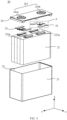
- FIG. 3 is a structural schematic diagram of a battery cell 20 according to an embodiment of this application.
- the battery cell 20 includes one or more electrode assemblies 22, a housing 21, and an end cover 24.
- the housing 21 and the end cover 24 form an outer shell or battery case. Walls of the housing 21 and the end covers 24 are all referred to as walls of the battery cell 20.
- the walls of the housing 21 include a bottom wall and four side walls, and the bottom wall and four side walls are connected to form an accommodating space 23 for accommodating the electrode assembly 22.
- the housing 21 depends on a combined shape of the one or more electrode assemblies 22.
- the housing 21 may be a hollow cuboid, a cube, or a cylinder, and one surface of the housing 21 has an opening for placing the one or more electrode assemblies 22 into the housing 21.
- one face of the housing 21 is an opening surface, which means that the face has no wall so that the inside and the outside of the housing 21 communicate with each other.
- the end face of the housing 21 is an opening surface, which means that the end face has no wall so that the inside and the outside of the housing 21 communicate with each other.
- the end cover 24 covers the opening of the accommodating space 23 and is connected to the housing 21 to form a closed chamber for accommodating the electrode assembly 22.
- the housing 21 is filled with an electrolyte such as a liquid electrolyte.
- the battery cell 20 may further include two electrode terminals 241, where the two electrode terminals 241 may be disposed on the end cover 24.
- the end cover 24 is typically in a flat plate shape, and the two electrode terminals 241 are fixed on a flat surface of the end covers 24.
- the two electrode terminals 241 are respectively a positive electrode terminal 241a and a negative electrode terminal 241b.
- Each electrode terminal 241 is provided with a corresponding connecting member 25, or a current collection member.
- the connecting member 25 is located between the end cover 24 and the electrode assembly 22 and is configured to electrically connect the electrode assembly 22 to the electrode terminal 241.
- one or more electrode assemblies 22 may be provided depending on an actual need. As shown in FIG. 3 , the battery cell 20 is provided with four independent electrode assemblies 22.
- the battery cell in the embodiments of this application can also be a pouch cell, where one or more electrode assemblies are directly packaged in a package, forming a pouch cell.
- the package can be made of aluminum-plastic film.
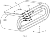
- FIG. 4 shows a structural schematic diagram of an electrode assembly 22 according to an embodiment of this application.
- the electrode assembly 22 is formed by winding electrode plates 221.
- the electrode plate 221 includes a current collector 2211 and a conductive structure 2212.
- the current collector 2211 includes an insulation layer 2211a and a conductive layer 2211b provided on an outer surface of the insulation layer 2211a.
- the conductive layer 2211b includes a body portion 2213 and a tab portion 2214 disposed along a first direction.
- the conductive structure 2212 is welded to the tab portion 2214, forming a welded zone 2215.
- the conductive structure 2212 extends away from the body portion 2213.
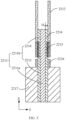
- the size L 1 of an end (such as L 1 shown in FIG. 6 ) of the welded zone 2215 near the body portion 2213 is greater than a preset threshold, where the preset threshold is inversely related to the thickness of the tab portion 2214 in a third direction.
- the first direction refers to an extending direction of the current collector 2211, for example, the first direction is direction x in FIG. 5 .
- the second direction is perpendicular to the first direction and parallel to the tab portion 2214, for example, the second direction is direction y in FIG. 6 .
- the third direction is perpendicular to both the first direction and the second direction, that is, perpendicular to the plane of the outer surface of the current collector, for example, the third direction is direction z in FIG. 5 .
- the current collector 2211 of the electrode plate 221 collects the current generated by the active substance layer to form a larger current output to the outside. Therefore, the current collector 2211 should be in sufficient contact with the active substance and have as low internal resistance as possible.
- the body portion 2213 of the conductive layer 2211b refers to a portion of the conductive layer 2211b that is located on an outer surface provided with the active substance layer 2217 and away from the insulation layer 2211a.
- an electrochemical reaction of the active substance layer 2217 converts chemical energy into electrical energy.
- the thickness of the conductive layer 2211b of the composite current collector is relatively small, resulting in insufficient current flow capacity of the tab.
- the conductive layer is widened to increase current flow capacity of the tab, but this also increases a space occupied, which may even affect the placement of other components inside the battery cell.
- a conductive structure 2212 with sufficient current flow capacity is welded to the conductive layer 2211b, so that the current flows from the body portion 2213 through the tab portion 2214 to the welded zone 2215, and then to the conductive structure 2212.
- the conductive structure 2212 is electrically connected to the electrode terminal 241 via the connecting member 25.
- the conductive structure 2212 has sufficient current flow capacity. After the conductive structure 2212 is welded to the tab portion 2214 to form the welded zone 2215, current flow capacity of a portion of the welded zone 2215 away from the body portion 2213 is mainly the current flow capacity of the conductive structure 2212. However, the end of the welded zone 2215 near the body portion 2213 is the starting end where the conductive structure 2212 is connected to the tab portion 2214. The current flow capacity at this location is also affected by the current flow capacity of the tab portion 2214. In addition, this location is the end portion of the welded zone 2215. If the current flow capacity is insufficient, a large amount of heat will be generated, and this end portion of the welded zone is prone to fuse, leading to repeated fusing and reconnection, which may cause sparks inside the battery.
- the electrode plate 221 includes a current collector 2211 and a conductive structure 2212.
- the conductive structure 2212 is welded to the tab portion 2214 of the current collector 2211, forming a welded zone 2215.
- the size L 1 of the end of the welded zone 2215 near the body portion 2213 in the second direction is greater than a preset threshold, where the preset threshold is inversely related to the thickness of the tab portion 2214 in the third direction.
- the preset threshold is L 2 ⁇ H 2 H 1 ⁇ C ⁇ A , where H 2 indicates thickness of an adapter piece at a minimum current flow width thereof 2212, L 2 indicates total width of connection surfaces between the conductive structure 2212 and the adapter piece at the minimum current flow width in the width direction of the adapter piece, H 1 indicates the thickness of the tab portion 2214 in the third direction, C indicates the number of conductive structures 2212 connected to one adapter piece, and A is a constant not less than 1.
- H 1 can be the thickness of the tab portion 2214 in the third direction z.
- the adapter piece can be the foregoing connecting member 25 in FIG. 3 .
- H 2 can be thickness of the connecting member 25 at a minimum current flow width in the first direction x
- L 2 can be total width of the connecting member 25 at the minimum current flow width in the second direction y, which is sum of the widths of the minimum current flow width on both sides of the connecting member 25 in FIG. 7 in the second direction y, or 2L 2 '. It should be understood that during the assembly process of the battery cell 20, multiple conductive structures 2212 are stacked together and connected to one adapter piece, so the number C of conductive structures 2212 connected to one adapter piece is introduced into the equation.
- the size L 1 of the end portion of the welded zone 2215 near the body portion 2213 in the second direction needs to be greater than the preset threshold L 2 ⁇ H 2 H 1 ⁇ C ⁇ A , so that the total current flow area of the end portion of the welded zone 2215 near the body portion 2213, formed on multiple conductive structures 2212, is greater than the current flow area of the corresponding adapter piece connected to the multiple conductive structures 2212.
- a total width L 2 of the connection surface between the adapter piece and the conductive structure 2212 at the minimum current flow width is 10 mm
- current flow area of the adapter piece is 8 mm 2 .
- the size L 1 of the end portion of the welded zone 2215 near the body portion 2213 in the second direction needs to be greater than 100 mm, so that the current flow capacity of the tab structure in the end portion of the welded zone 2215 near the body portion 2213 is greater than the current flow capacity of the corresponding adapter piece.
- the thickness H 2 at the minimum current flow width of the adapter piece is 0.8 mm
- a total width L 2 of the connection surface between the adapter piece and the conductive structure 2212 at the minimum current flow width is 20 mm
- the current flow area of the adapter piece is 16 mm 2 .
- the thickness H 1 of the tab portion 2214 in the third direction is 1 ⁇ m and the number C of conductive structures 2212 connected to one adapter piece is 120
- the size L 1 of the end portion of the welded zone 2215 near the body portion 2213 in the second direction needs to be greater than 134 mm, so that the current flow capacity of the tab structure in the end portion of the welded zone 2215 near the body portion 2213 is greater than the current flow capacity of the corresponding adapter piece.
- the constant A should be not less than 1.
- the size L 1 of the end portion of the welded zone 2215 should not be excessively large, so as to prevent lower plastics beneath the end cover 24 from compressing the conductive structure 2212. Therefore, the value of the constant A should not be excessively large, and the range of the constant A is 1 to 2.
- a protective layer 2216 is provided on a portion of the outer surface of the tab portion 2214.
- the protective layer 2216 is provided between the conductive structure 2212 and the active substance layer 2217, providing support to the tab portion 2214 and preventing deformation of the tab portion 2214 from affecting the current flow capacity of the electrode plate.
- the protective layer 2216 is made of an insulation material to prevent the protective layer 2216 from conducting and affecting the current flow path in the electrode plate 221, ensuring electrical connection safety of the electrode plate 221.
- the insulation material can include at least one of alumina trihydrate and hydroxide alumina.
- the protective layer 2216 can be formed on the outer surface of the tab portion 2214 via processes such as coating or plating.
- the tab portion 2214 includes a first tab portion 2214a and a second tab portion 2214b.
- the first tab portion 2214a is provided between the body portion 2213 and the second tab portion 2214b.
- the size of the first tab portion 2214a is greater than the size of the second tab portion 2214b.
- the size of the first tab portion 2214a is greater than the size of the second tab portion 2214b in the second direction y, that is, the first tab portion 2214a connected to the body portion 2213 has a relatively large size in the second direction y. This can increase the contact area between the body portion 2213 and the tab portion 2214, thereby increasing the connection strength, while the second tab portion 2214b has a relatively small size, which can reduce overall space occupied by the tab portion 2214.
- the size of the tab portion 2214 in the second direction y can change continuously and smoothly.
- the tab portion 2214 can have a triangular structure, trapezoidal structure, stepped structure, or the like.
- FIG. 6 illustrates an example where the tab portion 2214 is in a stepped structure.
- the welded zone 2215 includes a first welded zone 2215a and a second welded zone 2215b connected to the first welded zone 2215a.
- the first welded zone 2215a is located at the first tab portion 2214a
- the second welded zone 2215b is located at the second tab portion 2214b.
- the size of the first welded zone 2215a is greater than the size of the second welded zone 2215b.
- the second welded zone 2215b is located at the second tab portion 2214b, which has a larger size in the second direction y, so that the size L 1 of the end portion of the welded zone 2215 near the body portion 2213 in the second direction y is greater than the preset threshold, where the welded zone 2215 is formed during the tab portion 2214 is welded to the conductive structure 2212.
- the welding area between the second welded zone 2215b and the second tab portion 2214b is relatively large, which can improve the connection strength between them.
- the embodiments of this application further provide an electrode assembly 22, where the electrode assembly 22 can include the electrode plate 221 in the foregoing embodiments.
- the embodiments of this application further provide a battery cell 20, where the battery cell 20 can include a housing and the electrode assembly 22 in the foregoing embodiments.
- the housing is used for accommodating the electrode assembly 22.
- the housing has an opening
- the battery cell 20 further includes an end cover, where the end cover is configured to close the opening.
- the embodiments of this application further provide a battery 10, where the battery 10 can include the battery cell 20 in the foregoing embodiments.
- the battery 10 may further include other structures such as a box, busbars, and the like, which are not further described here.
- the embodiments of this application further provide an electric device, where the electric device can include the battery 10 in the foregoing embodiments.
- the electric device can be a vehicle 1, a ship, or a spacecraft, but this is not limited in the embodiments of this application.
Landscapes
- Chemical & Material Sciences (AREA)
- Chemical Kinetics & Catalysis (AREA)
- Electrochemistry (AREA)
- General Chemical & Material Sciences (AREA)
- Engineering & Computer Science (AREA)
- Materials Engineering (AREA)
- Manufacturing & Machinery (AREA)
- Composite Materials (AREA)
- Connection Of Batteries Or Terminals (AREA)
Applications Claiming Priority (2)
| Application Number | Priority Date | Filing Date | Title |
|---|---|---|---|
| CN202211374725.8A CN115425372B (zh) | 2022-11-04 | 2022-11-04 | 电极极片、电极组件、电池单体、电池和用电设备 |
| PCT/CN2023/083935 WO2024093100A1 (fr) | 2022-11-04 | 2023-03-26 | Feuille d'électrode, ensemble électrode, élément de batterie, batterie et dispositif électrique |
Publications (2)
| Publication Number | Publication Date |
|---|---|
| EP4391205A1 true EP4391205A1 (fr) | 2024-06-26 |
| EP4391205A4 EP4391205A4 (fr) | 2025-10-08 |
Family
ID=84207577
Family Applications (1)
| Application Number | Title | Priority Date | Filing Date |
|---|---|---|---|
| EP23844162.0A Pending EP4391205A4 (fr) | 2022-11-04 | 2023-03-26 | Feuille d'électrode, ensemble électrode, élément de batterie, batterie et dispositif électrique |
Country Status (4)
| Country | Link |
|---|---|
| US (1) | US20240243444A1 (fr) |
| EP (1) | EP4391205A4 (fr) |
| CN (1) | CN115425372B (fr) |
| WO (1) | WO2024093100A1 (fr) |
Cited By (2)
| Publication number | Priority date | Publication date | Assignee | Title |
|---|---|---|---|---|
| EP4668373A1 (fr) * | 2024-06-20 | 2025-12-24 | Samsung Sdi Co., Ltd. | Électrode et batterie secondaire |
| EP4687198A1 (fr) * | 2024-07-30 | 2026-02-04 | Samsung Sdi Co., Ltd. | Électrode et batterie secondaire |
Families Citing this family (9)
| Publication number | Priority date | Publication date | Assignee | Title |
|---|---|---|---|---|
| CN115425372B (zh) * | 2022-11-04 | 2023-04-14 | 江苏时代新能源科技有限公司 | 电极极片、电极组件、电池单体、电池和用电设备 |
| EP4421971A4 (fr) * | 2023-01-09 | 2025-07-09 | Contemporary Amperex Technology Hong Kong Ltd | Feuille d'électrode de batterie, ensemble électrode, élément de batterie, batterie et dispositif électrique |
| WO2024152260A1 (fr) * | 2023-01-18 | 2024-07-25 | 宁德时代新能源科技股份有限公司 | Élément de batterie, batterie et dispositif électrique |
| WO2024159413A1 (fr) * | 2023-01-31 | 2024-08-08 | 宁德时代新能源科技股份有限公司 | Élément de batterie, batterie et dispositif électrique |
| EP4475326A4 (fr) | 2023-04-24 | 2025-07-30 | Contemporary Amperex Technology Hong Kong Ltd | Feuille d'électrode, ensemble électrode, élément de batterie, batterie et dispositif électrique |
| CN116154416B (zh) * | 2023-04-24 | 2023-07-18 | 宁德时代新能源科技股份有限公司 | 极片、电极组件、电池单体、电池及用电设备 |
| CN117239058B (zh) * | 2023-11-13 | 2024-03-01 | 珠海冠宇电池股份有限公司 | 极片、电芯以及电池 |
| CN121794833A (zh) * | 2023-11-21 | 2026-04-03 | 珠海冠宇电池股份有限公司 | 极片、电芯及电池 |
| CN117691267B (zh) * | 2024-02-04 | 2024-04-12 | 蜂巢能源科技股份有限公司 | 电池及电池包 |
Family Cites Families (12)
| Publication number | Priority date | Publication date | Assignee | Title |
|---|---|---|---|---|
| CN106992313B (zh) * | 2016-01-20 | 2023-04-07 | 宁德新能源科技有限公司 | 二次电池 |
| CN111883740B (zh) * | 2018-06-22 | 2021-09-21 | 宁德时代新能源科技股份有限公司 | 一种极片及二次电池 |
| CN209087968U (zh) * | 2018-08-02 | 2019-07-09 | 宁德时代新能源科技股份有限公司 | 电极构件、电极组件及二次电池 |
| CN209183628U (zh) * | 2018-10-11 | 2019-07-30 | 宁德时代新能源科技股份有限公司 | 二次电池及其极片 |
| CN209747632U (zh) * | 2019-05-13 | 2019-12-06 | 宁德时代新能源科技股份有限公司 | 二次电池 |
| CN114975864A (zh) * | 2021-02-23 | 2022-08-30 | 北京小米移动软件有限公司 | 极片、电芯结构、锂电池以及电子设备 |
| CN113097662B (zh) * | 2021-03-31 | 2023-06-27 | 珠海冠宇电池股份有限公司 | 电池极片及其制备方法、锂离子电池 |
| CN215989130U (zh) * | 2021-08-19 | 2022-03-08 | 宁德时代新能源科技股份有限公司 | 电极组件、电池单体、电池以及用电装置 |
| CN216354652U (zh) * | 2021-11-30 | 2022-04-19 | 宁德时代新能源科技股份有限公司 | 电极组件及动力电池 |
| CN114566768A (zh) * | 2022-02-10 | 2022-05-31 | 东莞新能安科技有限公司 | 一种极片、电化学装置以及电子设备 |
| CN217589350U (zh) * | 2022-06-28 | 2022-10-14 | 中创新航科技股份有限公司 | 电池 |
| CN115425372B (zh) * | 2022-11-04 | 2023-04-14 | 江苏时代新能源科技有限公司 | 电极极片、电极组件、电池单体、电池和用电设备 |
-
2022
- 2022-11-04 CN CN202211374725.8A patent/CN115425372B/zh active Active
-
2023
- 2023-03-26 WO PCT/CN2023/083935 patent/WO2024093100A1/fr not_active Ceased
- 2023-03-26 EP EP23844162.0A patent/EP4391205A4/fr active Pending
-
2024
- 2024-03-31 US US18/623,015 patent/US20240243444A1/en active Pending
Cited By (2)
| Publication number | Priority date | Publication date | Assignee | Title |
|---|---|---|---|---|
| EP4668373A1 (fr) * | 2024-06-20 | 2025-12-24 | Samsung Sdi Co., Ltd. | Électrode et batterie secondaire |
| EP4687198A1 (fr) * | 2024-07-30 | 2026-02-04 | Samsung Sdi Co., Ltd. | Électrode et batterie secondaire |
Also Published As
| Publication number | Publication date |
|---|---|
| US20240243444A1 (en) | 2024-07-18 |
| CN115425372B (zh) | 2023-04-14 |
| WO2024093100A1 (fr) | 2024-05-10 |
| CN115425372A (zh) | 2022-12-02 |
| EP4391205A4 (fr) | 2025-10-08 |
Similar Documents
| Publication | Publication Date | Title |
|---|---|---|
| EP4391205A1 (fr) | Feuille d'électrode, ensemble électrode, élément de batterie, batterie et dispositif électrique | |
| EP4485660A1 (fr) | Boîtier, cellule de batterie, batterie et dispositif électrique | |
| CN218414936U (zh) | 电池单体、电池及用电设备 | |
| US20250105474A1 (en) | Battery cell, battery, and electric apparatus | |
| EP4258441A1 (fr) | Batterie, dispositif électrique et procédé et dispositif de préparation de batterie | |
| EP4297169A1 (fr) | Ensemble électrode, cellule de batterie, batterie et dispositif alimenté | |
| EP4068490A1 (fr) | Élément de batterie, batterie, dispositif électrique, et procédé et dispositif de fabrication pour élément de batterie | |
| EP4459767A1 (fr) | Couvercle supérieur de corps de boîtier de batterie, corps de boîtier de batterie, batterie et dispositif électrique | |
| US20230275296A1 (en) | Battery, power consumption device, and method and device for producing battery | |
| EP4354532A1 (fr) | Ensemble électrode, cellule de batterie, batterie et appareil électrique | |
| US20230268586A1 (en) | Battery, power consumption device, and method and device for producing battery | |
| EP4468485A1 (fr) | Élément de batterie, module de batterie, batterie et appareil consommateur d'énergie | |
| EP4250406A1 (fr) | Ensemble électrode et procédé et système de fabrication, cellule de batterie, batterie et appareil d'utilisation de puissance | |
| US20240339626A1 (en) | Electrode assembly, battery cell, battery, and electric device | |
| US20240339625A1 (en) | Battery electrode plate, electrode assembly, battery cell, battery, and electric device | |
| US20240332541A1 (en) | Electrode plate, electrode assembly, battery cell, battery, and electric device | |
| US12166242B2 (en) | Electrode plate, electrode assembly, battery cell, battery, and electric device | |
| US12249723B2 (en) | Battery, electric device, and method and device for preparing battery cell | |
| EP4571999A1 (fr) | Élément de batterie et son procédé de fabrication, batterie et dispositif électrique | |
| EP4432375A1 (fr) | Élément de batterie, batterie et dispositif électrique | |
| EP4683101A1 (fr) | Élément de connexion, élément de batterie, batterie et dispositif électrique | |
| EP4428998A1 (fr) | Élément de batterie, batterie et dispositif électrique | |
| EP4661204A1 (fr) | Élément de batterie, batterie et dispositif électronique | |
| CN223757523U (zh) | 电池单体、电池装置和用电装置 | |
| US20250391962A1 (en) | Battery cell, battery, electric device, and method for assembling battery |
Legal Events
| Date | Code | Title | Description |
|---|---|---|---|
| STAA | Information on the status of an ep patent application or granted ep patent |
Free format text: STATUS: UNKNOWN |
|
| STAA | Information on the status of an ep patent application or granted ep patent |
Free format text: STATUS: THE INTERNATIONAL PUBLICATION HAS BEEN MADE |
|
| PUAI | Public reference made under article 153(3) epc to a published international application that has entered the european phase |
Free format text: ORIGINAL CODE: 0009012 |
|
| STAA | Information on the status of an ep patent application or granted ep patent |
Free format text: STATUS: REQUEST FOR EXAMINATION WAS MADE |
|
| 17P | Request for examination filed |
Effective date: 20240131 |
|
| AK | Designated contracting states |
Kind code of ref document: A1 Designated state(s): AL AT BE BG CH CY CZ DE DK EE ES FI FR GB GR HR HU IE IS IT LI LT LU LV MC ME MK MT NL NO PL PT RO RS SE SI SK SM TR |
|
| A4 | Supplementary search report drawn up and despatched |
Effective date: 20250909 |
|
| RIC1 | Information provided on ipc code assigned before grant |
Ipc: H01M 50/533 20210101AFI20250903BHEP Ipc: H01M 4/13 20100101ALI20250903BHEP Ipc: H01M 10/052 20100101ALI20250903BHEP Ipc: H01M 10/0525 20100101ALI20250903BHEP Ipc: H01M 10/054 20100101ALI20250903BHEP Ipc: H01M 50/536 20210101ALI20250903BHEP Ipc: H01M 50/586 20210101ALI20250903BHEP Ipc: H01M 50/595 20210101ALI20250903BHEP Ipc: H01M 4/66 20060101ALI20250903BHEP Ipc: H01M 10/0587 20100101ALI20250903BHEP Ipc: H01M 50/531 20210101ALI20250903BHEP Ipc: H01M 50/534 20210101ALI20250903BHEP |
|
| DAV | Request for validation of the european patent (deleted) | ||
| DAX | Request for extension of the european patent (deleted) |