EP4391277A1 - Procédé de déconnexion d'un ensemble batterie d'un dispositif électronique et procédé de fonctionnement d'un ensemble électronique - Google Patents
Procédé de déconnexion d'un ensemble batterie d'un dispositif électronique et procédé de fonctionnement d'un ensemble électronique Download PDFInfo
- Publication number
- EP4391277A1 EP4391277A1 EP22215073.2A EP22215073A EP4391277A1 EP 4391277 A1 EP4391277 A1 EP 4391277A1 EP 22215073 A EP22215073 A EP 22215073A EP 4391277 A1 EP4391277 A1 EP 4391277A1
- Authority
- EP
- European Patent Office
- Prior art keywords
- battery
- electronic device
- disconnected
- arrangement
- string
- Prior art date
- Legal status (The legal status is an assumption and is not a legal conclusion. Google has not performed a legal analysis and makes no representation as to the accuracy of the status listed.)
- Pending
Links
Images


Classifications
-
- H—ELECTRICITY
- H02—GENERATION; CONVERSION OR DISTRIBUTION OF ELECTRIC POWER
- H02J—ELECTRIC POWER NETWORKS; CIRCUIT ARRANGEMENTS OR SYSTEMS FOR SUPPLYING OR DISTRIBUTING ELECTRIC POWER; SYSTEMS FOR STORING ELECTRIC ENERGY
- H02J7/00—Circuit arrangements for charging or discharging batteries or for supplying loads from batteries
- H02J7/50—Circuit arrangements for charging or discharging batteries or for supplying loads from batteries acting upon multiple batteries simultaneously or sequentially
-
- H—ELECTRICITY
- H02—GENERATION; CONVERSION OR DISTRIBUTION OF ELECTRIC POWER
- H02J—ELECTRIC POWER NETWORKS; CIRCUIT ARRANGEMENTS OR SYSTEMS FOR SUPPLYING OR DISTRIBUTING ELECTRIC POWER; SYSTEMS FOR STORING ELECTRIC ENERGY
- H02J7/00—Circuit arrangements for charging or discharging batteries or for supplying loads from batteries
- H02J7/60—Circuit arrangements for charging or discharging batteries or for supplying loads from batteries including safety or protection arrangements
- H02J7/663—Circuit arrangements for charging or discharging batteries or for supplying loads from batteries including safety or protection arrangements using battery or load disconnect circuits
-
- H—ELECTRICITY
- H02—GENERATION; CONVERSION OR DISTRIBUTION OF ELECTRIC POWER
- H02J—ELECTRIC POWER NETWORKS; CIRCUIT ARRANGEMENTS OR SYSTEMS FOR SUPPLYING OR DISTRIBUTING ELECTRIC POWER; SYSTEMS FOR STORING ELECTRIC ENERGY
- H02J7/00—Circuit arrangements for charging or discharging batteries or for supplying loads from batteries
- H02J7/855—Circuit arrangements for charging or discharging batteries or for supplying loads from batteries with circuits adapted for supplying loads from the battery
-
- H—ELECTRICITY
- H02—GENERATION; CONVERSION OR DISTRIBUTION OF ELECTRIC POWER
- H02J—ELECTRIC POWER NETWORKS; CIRCUIT ARRANGEMENTS OR SYSTEMS FOR SUPPLYING OR DISTRIBUTING ELECTRIC POWER; SYSTEMS FOR STORING ELECTRIC ENERGY
- H02J2105/00—Networks for supplying or distributing electric power characterised by their spatial reach or by the load
- H02J2105/30—Networks for supplying or distributing electric power characterised by their spatial reach or by the load the load networks being external to vehicles, i.e. exchanging power with vehicles
Definitions
- the invention relates to the field of battery arrangements.
- the invention relates to a method for disconnecting a battery arrangement from an electronic device, and to a method for operating an electronic arrangement, which comprises the battery arrangement and the electronic device.
- An increasing number of vehicles e.g. cars, trains, subways, busses, is equipped with battery cells, in particular high-performance battery cells.
- a typical standard or high-performance battery cell may have a nominal capacity between 1 Ah and 1000 Ah and may be used for driving the corresponding vehicle, in particular for providing energy to a power train of the corresponding vehicle.
- Conventional high-performance battery cells may be encapsulated in battery modules, wherein the battery modules may be fully assembled as battery strings. Then, the battery strings may be combined in one battery arrangement, wherein the battery strings may be electrically coupled to each other in parallel.
- Each of the battery strings may comprise a separate switch for disconnecting the corresponding battery string from an electronic device which may be external with respect to the battery arrangement.
- This electronic device may be a load or a generator, or a converter, an inverter, or a rectifier, e.g. for coupling the battery arrangement to the load or the generator.
- the battery arrangements may be arranged in the vehicles, e.g. for driving the vehicles.
- the battery arrangements are not designed to be removed easily, e.g. in order to check, maintain, and/or exchange one or more of the battery strings or its switches.
- intense efforts have to be taken to check, maintain or exchange the battery strings and/or their switches, and/or to find out which battery string has caused a defect of the battery arrangement.
- the same battery string and/or switch is the last, because of fixed product tolerances of the battery strings and, respectively, corresponding switches. This contributes to that the last battery string and the corresponding last switch wears very fast compared to all other battery strings and corresponding switches. This may contribute to relatively short maintenance intervals and/or a short lifetime of the corresponding switch and thereby of the corresponding battery string and of the battery arrangement.
- an objective of the present invention is achieved by a method for disconnecting a battery arrangement from an electronic device, wherein the battery arrangement comprises two or more battery strings and wherein the battery strings are electrically coupled to the electronic device in parallel.
- the method comprises disconnecting the battery strings from the electronic device one after the other in accordance with a predetermined temporal sequence until all of the battery strings are disconnected from the electronic device. This may contribute to that wear of the battery arrangement may be distributed over the battery strings over time in a known manner. This may contribute to an easy and quick maintenance of the battery arrangement, when necessary.
- Each of the battery strings may comprise one or more battery modules, wherein each of the battery modules may comprise one or more battery cells and one or more electronic components for driving the battery cells.
- the battery cells may be high-performance battery cells having a nominal capacity between 1 Ah and 1000 Ah, e.g. between 20 Ah and 500 Ah, e.g. between 25 Ah and 100 Ah.
- the temporal sequence is predetermined such that every time the battery strings are disconnected from the electronic device, the last battery string to be disconnected is one predetermined battery string of the battery strings.
- one of the battery strings may be predetermined to be the last one to be disconnected every time the battery arrangement is disconnected from the electronic device.
- This predetermined battery string may be referred to as "sacrificial battery string”. This may contribute to that the wear of the battery arrangement is focused on the sacrificial battery string. So, after a predetermined time or if the battery arrangement has a failure, it is known with a very high reliability, which one of the battery strings has to be maintained, i.e. the sacrificial battery string.
- the sacrificial battery string may be maintained and/or fully or partly exchanged first and because the remaining battery strings may be maintained and/or fully or partly exchanged later or not at all. Further, the sacrificial battery string may be formed and/or arranged such that it may be maintained and/or fully or partly exchanged easily compared to the other battery strings.
- the temporal sequence may stay the same over all or at least several disconnection operations.
- the temporal sequence may refer to one disconnection operation only, wherein the disconnection operation may refer to the disconnection of the battery arrangement from the electronic device.
- the temporal sequence may be altered such that the order of the battery strings to be disconnected is altered from one disconnection operation to the next disconnection operation, wherein only the sacrificial battery string stays the same, i.e. the last of the battery strings to be disconnected.
- the temporal sequence may refer to two or more of the disconnection operations, wherein the sacrificial string to be disconnected at last may be the fixpoint of the temporal sequence over these disconnection operations.
- the temporal sequence is predetermined such that the last battery string to be disconnected from the electronic device is one of the battery strings in one disconnection operation and another one of the battery strings in another disconnection operation. This contributes to that the last battery string to be disconnected from the electronic device is not always the same of the battery strings, and that the last battery string to be disconnected from the electronic device is altered. This may contribute to a long lifetime of the battery strings and as such of the battery arrangement.
- the temporal sequence is predetermined such that every time the battery arrangement is disconnected from the electronic device, the last battery string to be disconnected from the electronic device is another battery string than that one which has been disconnected from the electronic device at last the last time the battery arrangement has been disconnected from the electronic device, i.e. in the previous disconnection operation.
- the order according to which the battery strings are disconnected from the electronic device and the last battery string to be disconnected may change every time the battery arrangement is disconnected from the electronic device. This contributes to that the wear of the battery arrangement is distributed over all of the battery strings. This may contribute to that the lifetime of the battery strings and thereby of the battery arrangement is increased and/or that a maintenance interval for maintaining the battery arrangement may be very long.
- the temporal sequence may refer to two or more of the disconnection operations, wherein the battery string to be disconnected at last may alter from one disconnection operation to the other disconnection operation.
- the temporal sequence is predetermined such that when all of the battery strings have been the last battery string to be disconnected from the electronic device, e.g. for a given amount of times, the battery string to be disconnected at last is the same battery string which has been disconnected at last when the temporal sequence has been started the previous time.
- the temporal sequence starts with disconnecting that battery string at last which has been disconnected at last firstly, and the temporal sequence may start again. This may contribute to that the wear is distributed over all of the battery strings, at least after the amount of disconnection operations equals the amount of battery strings.
- the temporal sequence is predetermined such that over several disconnection operations it is equally distributed over all of the battery strings which of the battery strings has been the last one to be disconnected from the electronic device.
- the temporal sequence may be predetermined such that after a given amount of disconnection operations each of the battery strings has been the last one to be disconnected for the amount divided by the number of battery strings.
- the battery arrangement comprises for example three battery strings
- the temporal sequence may be predetermined such that after for example 100 disconnection operations each of the battery strings has been the last one to be disconnected for about 33 times. This contributes to that the wear of the battery arrangement is distributed over all of the battery strings equally. This may contribute to that the lifetime of the battery strings and thereby of the battery arrangement may be long and/or that a maintenance interval for maintaining the battery arrangement may be very long.
- each of the battery strings comprises a corresponding switch for disconnecting the corresponding battery string from the electronic device, wherein the battery strings are disconnected from the electronic device by opening the corresponding switch.
- the switches may be electronic switches.
- each of the switches has an individual delay for disconnecting the corresponding battery string from the electronic device after being actuated
- the predetermined temporal sequence comprises several consecutive time intervals, after each of the time intervals one of the switches is actuated, and each of the time intervals is larger than the maximum delay of all delays of the switches. This may contribute to that the switches disconnect the corresponding battery string from the electronic device in a manner which is predetermined by the predetermined temporal sequence. In particular, this may contribute to that the switches disconnect the corresponding battery string from the electronic device in the same order in which the switches are actuated, which is in accordance with the predetermined temporal sequence.
- the switch is an electronic switch.
- the switch may be actuated mechanically or electronically.
- the switch may be a contactor, a relay, a semiconductor switch, or a circuit breaker.
- the electronic device is a generator, a load, a converter, an inverter, or a rectifier.
- the electronic device may be an electrical machine which may be operated in a motor mode or in a generator mode, or the electronic device may be electrically coupled to the electrical machine.
- An objective of the present invention is achieved by a method for operating an electronic arrangement, wherein the electronic arrangement comprises a battery arrangement and at least one electronic device, the method comprising: disconnecting the battery arrangement from the electronic device by the method in accordance with one of the preceding claims.
- the electronic device may be a part of the electronic arrangement but may be external with respect to the battery arrangement.
- Fig. 1 schematically shows a side view of an exemplary embodiment of an electronic arrangement 20.
- the electronic arrangement 20 may be arranged in a car, a train, a subway, a bus, etc.
- the electronic arrangement comprises a battery arrangement 22 and an electronic device 24.
- the battery arrangement 22 comprises two or more battery strings, e.g. n battery strings, e.g. a first battery string 30, a second battery string 32, and an n th battery string 34, wherein n is a natural number equal or larger than two.
- the battery strings 30, 32, 34 are electrically arranged in parallel.
- Each of the battery strings 30, 32, 34 may comprise one or more battery modules, with each of the battery modules comprising one or more battery cells.
- the battery arrangement 22 may be referred to as battery pack.
- the battery arrangement 22 may comprise a housing (not shown).
- the battery arrangement 22 may be configured for providing energy to an electric motor and/or to receive and store electric energy by a generator, wherein the battery arrangement 22 and/or the electronic device 24 may be electrically coupled to an electric machine which may be operated as the electric motor or as the generator.
- the battery cells may be high-performance battery cells. Each of the high-performance battery cells may have a nominal capacity between 1 Ah and 1000 Ah. The nominal capacity may be between 20 Ah and 500 Ah, e.g. between 25 Ah and 100 Ah.
- Each of the battery strings 30, 32, 34 may comprise a switch.
- the first battery string 30 may comprise a first switch 40
- the second battery string 32 may comprise a second switch 42
- the third battery string 34 may comprise a third switch 44.
- the switches 40, 42, 44 may be configured for disconnecting the corresponding battery string 30, 32, 34 from the electronic device 24, wherein the battery strings 30, 32, 34 may be disconnected from the electronic device 24 by opening the corresponding switch 40, 42, 44.
- the switches may be electronic switches.
- the switches may be actuated mechanically or electronically.
- each of the switches 40, 42, 44 may be a contactor, a relay or a circuit breaker.
- Each of the switches 40, 42, 44 may have an individual delay for disconnecting the corresponding battery string 30, 32, 34 from the electronic device 24 after being actuated. In fact, even if the same type of switch is used for all of the switches 40, 42, 44 their individual reaction times may differ from each other a little bit, because of production tolerances. So, even if the switches 40, 42, 44 are actuated simultaneously, in particular for disconnecting the corresponding battery string 30, 32, 34 from the electronic device 24, the switches 40, 42, 44 may disconnect the battery strings 30, 32, 34 one after the other.
- the switch 40, 42, 44 with the longest delay in other words the "slowest" switch 40, 42, 44 may stay the same.
- the slowest switch 40, 42, 44 is not known in advance. This may lead to problems in case of a maintenance and/or failure of the battery arrangement 22, as explained in the introductory part of this application and in the following with respect to figures 2 and 3 . Therefore, the battery arrangement 22 may be operated in accordance with a predetermined temporal sequence, as explained below and with respect to figure 4 .
- the electronic device 24 may be a load, e.g. the electric machine, a converter, an inverter, or a rectifier.
- the electronic device 24 is external with respect to the battery arrangement 22.
- the electronic arrangement 20 may comprise a battery management system (BMS) (not shown) for controlling the switches 40, 42, 44.
- BMS battery management system
- the battery arrangement 22, e.g. one or more of the battery strings 30, 32, 34, may comprise the BMS or a part of the BMS.
- the switches 40, 42, 44 may be controlled by a device (not shown) which is external with respect to the electronic arrangement 20.
- Fig. 2 schematically shows examples of a first current diagram 50, a voltage diagram 52, and an energy diagram 54, each showing the corresponding parameter vs. time t.
- the battery arrangement 22 comprises three battery strings 40, 42, 44 ("String 1", “String 2", and “String 3" in figure 2 ), so in this case the above-mentioned parameter n is 3.
- the time-axis of the diagrams 50, 52, 54 is separated in several time intervals depending on the switches 40, 42, 44 which are connected to the electronic device 24.
- a first time interval 56 all three battery strings 30, 32, 34 are connected to the electronic device 24 and the switches 40, 42, 44 are closed, wherein the switches 40, 42, 44 may be contactors, relays, or circuit breakers in this embodiment.
- a second time interval 58 one of the battery strings 30, 32, 34 is disconnected from the electronic device 24 and the corresponding switch 40, 42, 44 is opened.
- a third time interval 60 another one of the battery strings 30, 32, 34 is disconnected from the electronic device 24 and the corresponding switch 40, 42, 44 is opened.
- a total current I ESS over all three battery strings 30, 32, 34 is distributed equally over all of the three battery strings 30, 32, 34, as it is normal for battery strings 30, 34, 34 which are electrically arranged in parallel. So, each of the battery strings 30, 32, 34 carries one third of the total current less, i.e. I ESS /3.
- commutation point 64 At the beginning of the second and third time intervals 58, 60 there is a commutation point 64 each. At each of the commutation points 64, one of the battery strings 30, 32, 34 is disconnected from the electronic device 24, in particular by an opening of the corresponding switch 40, 42, 44. At the time of these commutation points 64, the voltage diagram 52 shows a slight voltage increase 68, which is sufficient to push the current from the disconnected one of the battery strings 30, 32, 34 to firstly the remaining battery strings 30, 32, 34, and then to the last remaining battery string 30, 32, 34.
- the two connected ones of the battery strings 30, 32, 34 carry the half of the total current I ESS , i.e. I ESS /2
- the last connected one of the battery strings 30, 32, 34 ( “String 3" in figure 2 ) carries the total current less, i.e. I ESS /2.
- a time which is needed to push the current from the disconnected battery string 30, 32, 34 to the remaining battery string(s) 30, 32, 34 may be several milliseconds, wherein 1 kA may be commutated in these several milliseconds.
- the last one of the battery strings 30, 32, 34 is disconnected from the electronic device 24.
- the corresponding curve in the first diagram 50 shows a break point 66 at which the current drops from nearly the total current I ESS towards zero.
- the voltage over the same battery string 30, 32, 34 (“String 3" in figure 2 ) correspondingly increases to its maximum value, e.g. 750 V in the example shown in figure 2 .
- the energy diagram 54 shows an energy distribution of an energy which is released, e.g. by a corresponding arc at the corresponding switch 40, 42, 44.
- the energy of the corresponding arc is negligible in the first to third time intervals 56, 58, 60.
- the energy 70 at the last battery string 30, 32, 34 to be disconnected may jump up to almost 100 %, because the last battery string 30, 32, 34, in particular the last switch 40, 42, 44, to be opened ("String 3" in figure 2 ) has to break nearly 100 % of the current, which may cause an arc.
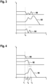
- FIG. 3 schematically shows an example of a second current diagram.
- figure 3 shows the currents within the battery strings 30, 32, 34 in one single disconnection operation, in which all of the battery strings 30, 32, 34 are disconnected from the electronic device 24, as it is known in the prior art.
- the second current diagram shows a first curve 80 being representative for the current within the first string 30, a second curve 82 being representative for the current within the second string 32, and a third curve 84 being representative for the current within the n th string 34.
- the last or slowest one of the battery strings 30, 32, 34 which is the second battery string 32 in this example, has to firstly carry all the current and then the corresponding switch 42, which is the second switch 42 in this example, has to break all the current.
- FIG. 4 schematically shows an example of a third current diagram.
- figure 4 shows the currents within the battery strings 30, 32, 34 in another single disconnection operation, in which all of the battery strings 30, 32, 34 are disconnected from the electronic device 24 in accordance with the predetermined temporal sequence.
- the third current diagram shows a fourth curve 90 being representative for the current within the first string 30, a fifth curve 92 being representative for the current within the second string 32, and a sixth curve 84 being representative for the current within the n th string 34.
- the first battery string 30 is disconnected from the electronic device 24, in particular by actuating the first switch 40.
- the second battery string 32 is disconnected from the electronic device 24, in particular by actuating the second switch 42.
- the n th battery string 34 is disconnected from the electronic device 24, in particular by actuating the n th switch 44.
- the time points t 1 , t 2 , t 3 may be chosen such that a time difference ⁇ t between the time points t 1 , t 2 , t 3 may be always the same.
- the time differences ⁇ t are larger than the delay of the slowest battery string 30, 32, 34, in particular the slowest switch 40, 42, 44.
- the predetermined temporal sequence may comprise several consecutive time intervals, and after each of the time intervals one predetermined one of the switches 40, 42, 44 may be actuated, wherein each of the time intervals may be larger than the maximum delay of all delays of the switches 40, 42, 44. So, because of the predetermined temporal sequence, the battery string 30, 32, 34 and/or the switch 40, 42, 44 which wears most and/or at the fastest may be known in advance.
- a method for disconnecting the battery arrangement 22 from the electronic device 24 may comprise disconnecting the battery strings 30, 32, 34 from the electronic device 24 one after the other in accordance with the predetermined temporal sequence until all of the battery strings 30, 32, 34 are disconnected from the electronic device 24.
- the temporal sequence may be predetermined such that every time the battery strings 30, 32, 34 are disconnected from the electronic device, in other words for each disconnection operation, the last battery string 30, 32, 34 to be disconnected is one predetermined battery string of the battery strings 30, 32, 34.
- one of the battery strings 30, 32, 34 may be predetermined to be the last one to be disconnected every time the battery arrangement 22 is disconnected from the electronic device 24.
- This predetermined battery string 30, 32, 34 may be referred to as sacrificial battery string, and may be the n th battery string in the example presented by figure 4 .
- the wear of the battery arrangement 22 is focused on the sacrificial battery string only. So, after a predetermined time or if the battery arrangement 22 has a failure, it is known with a very high reliability, which one of the battery strings 30, 32, 34 has to be maintained and/or exchanged, i.e. the sacrificial battery string.
- the sacrificial battery string may be formed and/or arranged such that it may be maintained and/or exchanged easily compared to the other battery strings 30, 32, 34.
- the temporal sequence may stay the same over all or at least several disconnection operations.
- the temporal sequence may refer to one disconnection operation only.
- the temporal sequence may be altered such that the order of the battery strings 30, 32, 34 to be disconnected is altered from one disconnection operation to the next disconnection operation, wherein only the sacrificial battery string stays the same.
- the temporal sequence may refer to two or more of the disconnection operations, wherein the sacrificial battery string to be disconnected at last may be the fixpoint of the temporal sequence over these disconnection operations.
- the temporal sequence may be predetermined such that the last battery string 30, 32, 34 to be disconnected from the electronic device 24 is one of the battery strings 30, 32, 34 in one disconnection operation and another one of the battery strings 30, 32, 34 in another disconnection operation. So, the "last" battery string 30, 32, 34 may be altered such that the wear may be distributed over more than one battery string 30, 32, 34, independent from their individual delay.
- the temporal sequence may be predetermined such that every time the battery arrangement 22 is disconnected from the electronic device 24, the last battery string 30, 32, 34 to be disconnected from the electronic device 24 is another battery string 30, 32, 34 than that one which has been disconnected from the electronic device 24 at last the last time the battery arrangement 22 has been disconnected from the electronic device 24.
- the order according to which the battery strings 30, 32, 34 are disconnected from the electronic device 24 may change, e.g. every time, when the battery arrangement 22 is disconnected from the electronic device 24. This may contribute to that the wear of the battery arrangement 22 is distributed over all of the battery strings 30, 32, 34 and, in particular, switches 40, 42, 44.
- the temporal sequence may refer to two or more of the disconnection operations, wherein the battery string 30, 32, 34 to be disconnected at last may alter from one disconnection operation to the other disconnection operation.
- the temporal sequence may be predetermined such that when all of the battery strings 30, 32, 34 have been the last battery string 30, 32, 34 to be disconnected from the electronic device 24, e.g. for a given amount of times, the battery string 30, 32, 34 to be disconnected at last is the same battery string 30, 32, 34 which has been disconnected at last when the temporal sequence has been started the previous time.
- the temporal sequence may start with disconnecting that battery string 30, 32, 34 at last which has been disconnected at last firstly, and the temporal sequence may start again.
- the temporal sequence may be predetermined such that over several disconnection operations it is equally distributed over all of the battery strings 30, 32, 34 which of the battery strings 30, 32, 34 has been the last one to be disconnected from the electronic device 24.
- the battery arrangement 22 comprises a given number of battery strings 30, 32, 34
- the temporal sequence may be predetermined such that after a given amount of disconnection operations each of the battery strings 30, 32, 34 has been the last one to be disconnected for the amount divided by the number of battery strings.
- the battery arrangement 22 comprises for example the above three battery strings 30, 32, 34
- the temporal sequence may be predetermined such that after for example 100 disconnection operations each of the battery strings 30, 32, 34 has been the last one to be disconnected for about 33 times. This contributes to that the wear of the battery arrangement 22 is distributed over all of the battery strings 30, 32, 34 equally.
Landscapes
- Engineering & Computer Science (AREA)
- Power Engineering (AREA)
- Charge And Discharge Circuits For Batteries Or The Like (AREA)
Priority Applications (1)
| Application Number | Priority Date | Filing Date | Title |
|---|---|---|---|
| EP22215073.2A EP4391277A1 (fr) | 2022-12-20 | 2022-12-20 | Procédé de déconnexion d'un ensemble batterie d'un dispositif électronique et procédé de fonctionnement d'un ensemble électronique |
Applications Claiming Priority (1)
| Application Number | Priority Date | Filing Date | Title |
|---|---|---|---|
| EP22215073.2A EP4391277A1 (fr) | 2022-12-20 | 2022-12-20 | Procédé de déconnexion d'un ensemble batterie d'un dispositif électronique et procédé de fonctionnement d'un ensemble électronique |
Publications (1)
| Publication Number | Publication Date |
|---|---|
| EP4391277A1 true EP4391277A1 (fr) | 2024-06-26 |
Family
ID=84547266
Family Applications (1)
| Application Number | Title | Priority Date | Filing Date |
|---|---|---|---|
| EP22215073.2A Pending EP4391277A1 (fr) | 2022-12-20 | 2022-12-20 | Procédé de déconnexion d'un ensemble batterie d'un dispositif électronique et procédé de fonctionnement d'un ensemble électronique |
Country Status (1)
| Country | Link |
|---|---|
| EP (1) | EP4391277A1 (fr) |
Citations (4)
| Publication number | Priority date | Publication date | Assignee | Title |
|---|---|---|---|---|
| US20170120772A1 (en) * | 2015-10-30 | 2017-05-04 | Faraday&Future Inc. | Electric vehicle battery charge and discharge management |
| US20190288538A1 (en) * | 2018-03-19 | 2019-09-19 | Dell Products L.P. | System and Method to Improve Battery Performance with Cycled Current Transfer |
| EP4084035A1 (fr) * | 2021-04-29 | 2022-11-02 | Volvo Truck Corporation | Agencement de commutation |
| EP4084265A1 (fr) * | 2021-04-29 | 2022-11-02 | Volvo Truck Corporation | Procédé de fonctionnement d'un agencement de commutation d'un système de stockage d'énergie |
-
2022
- 2022-12-20 EP EP22215073.2A patent/EP4391277A1/fr active Pending
Patent Citations (4)
| Publication number | Priority date | Publication date | Assignee | Title |
|---|---|---|---|---|
| US20170120772A1 (en) * | 2015-10-30 | 2017-05-04 | Faraday&Future Inc. | Electric vehicle battery charge and discharge management |
| US20190288538A1 (en) * | 2018-03-19 | 2019-09-19 | Dell Products L.P. | System and Method to Improve Battery Performance with Cycled Current Transfer |
| EP4084035A1 (fr) * | 2021-04-29 | 2022-11-02 | Volvo Truck Corporation | Agencement de commutation |
| EP4084265A1 (fr) * | 2021-04-29 | 2022-11-02 | Volvo Truck Corporation | Procédé de fonctionnement d'un agencement de commutation d'un système de stockage d'énergie |
Similar Documents
| Publication | Publication Date | Title |
|---|---|---|
| US11052843B2 (en) | Battery arrangement for a motor vehicle | |
| US10919467B2 (en) | HV battery arrangement for a motor vehicle, onboard network, motor vehicle, and method for controlling an HV battery arrangement | |
| US10464426B2 (en) | High-voltage vehicle electrical system having a pyrotechnic disconnecting device, and method for operating the high-voltage vehicle electrical system | |
| CN113195297B (zh) | 用于机动车尤其是混合动力车或电动车的电路装置 | |
| JP6214540B2 (ja) | バッテリーのセルブロックをスイッチングすることによってバッテリーの充放電レベルを平衡化するための方法 | |
| KR102161639B1 (ko) | 배터리 시스템 및 이의 작동 방법 | |
| CN106960943A (zh) | 具有更高可靠性的牵引电池 | |
| CN109649216B (zh) | 驱动电池的自动连接 | |
| US9997938B2 (en) | Circuit arrangement and a method for charging a dc link capacitor, as well as a battery and motor vehicle comprising such a circuit arrangement | |
| JP6024801B1 (ja) | スイッチング装置、移動体、電力供給システム及びスイッチング方法 | |
| JP2012517003A (ja) | 使用性が向上した駆動バッテリー | |
| CN115943535A (zh) | 配电模块 | |
| US9331504B2 (en) | Method for charging a battery | |
| EP3564062A1 (fr) | Système de circuit pour véhicule ferroviaire | |
| EP4391277A1 (fr) | Procédé de déconnexion d'un ensemble batterie d'un dispositif électronique et procédé de fonctionnement d'un ensemble électronique | |
| US12191092B2 (en) | Contactor device and energy storage system | |
| US20240097459A1 (en) | Electrical circuit for a high-voltage network of a vehicle | |
| EP3618141B1 (fr) | Emplacement de fusibles dans un système de stockage de batterie | |
| CN112714979A (zh) | 用于分离电池的方法 | |
| CN117879081A (zh) | 用于车辆的高压网络的电路 | |
| KR102729874B1 (ko) | 차량의 다중 모터 구동 시스템 | |
| US10807473B2 (en) | On-board network for a motor vehicle and method for operating an on-board network for a motor vehicle | |
| EP3618142B1 (fr) | Concept de mise à la terre et de déconnexion de service pour système de stockage de batterie | |
| US20250388184A1 (en) | Power supply apparatus | |
| EP4498552A1 (fr) | Système de distribution d'énergie à voies multiples |
Legal Events
| Date | Code | Title | Description |
|---|---|---|---|
| PUAI | Public reference made under article 153(3) epc to a published international application that has entered the european phase |
Free format text: ORIGINAL CODE: 0009012 |
|
| STAA | Information on the status of an ep patent application or granted ep patent |
Free format text: STATUS: THE APPLICATION HAS BEEN PUBLISHED |
|
| AK | Designated contracting states |
Kind code of ref document: A1 Designated state(s): AL AT BE BG CH CY CZ DE DK EE ES FI FR GB GR HR HU IE IS IT LI LT LU LV MC ME MK MT NL NO PL PT RO RS SE SI SK SM TR |
|
| STAA | Information on the status of an ep patent application or granted ep patent |
Free format text: STATUS: REQUEST FOR EXAMINATION WAS MADE |
|
| 17P | Request for examination filed |
Effective date: 20241015 |
|
| RBV | Designated contracting states (corrected) |
Designated state(s): AL AT BE BG CH CY CZ DE DK EE ES FI FR GB GR HR HU IE IS IT LI LT LU LV MC ME MK MT NL NO PL PT RO RS SE SI SK SM TR |