EP4391297A1 - Unterbrechungsfreie stromversorgung - Google Patents
Unterbrechungsfreie stromversorgung Download PDFInfo
- Publication number
- EP4391297A1 EP4391297A1 EP23213207.6A EP23213207A EP4391297A1 EP 4391297 A1 EP4391297 A1 EP 4391297A1 EP 23213207 A EP23213207 A EP 23213207A EP 4391297 A1 EP4391297 A1 EP 4391297A1
- Authority
- EP
- European Patent Office
- Prior art keywords
- power supply
- supply circuit
- terminals
- circuit
- uninterruptible power
- Prior art date
- Legal status (The legal status is an assumption and is not a legal conclusion. Google has not performed a legal analysis and makes no representation as to the accuracy of the status listed.)
- Pending
Links
Images



Classifications
-
- H—ELECTRICITY
- H02—GENERATION; CONVERSION OR DISTRIBUTION OF ELECTRIC POWER
- H02J—ELECTRIC POWER NETWORKS; CIRCUIT ARRANGEMENTS OR SYSTEMS FOR SUPPLYING OR DISTRIBUTING ELECTRIC POWER; SYSTEMS FOR STORING ELECTRIC ENERGY
- H02J9/00—Circuit arrangements for emergency or stand-by power supply, e.g. for emergency lighting
- H02J9/04—Circuit arrangements for emergency or stand-by power supply, e.g. for emergency lighting in which the distribution system is disconnected from the normal source and connected to a standby source
- H02J9/06—Circuit arrangements for emergency or stand-by power supply, e.g. for emergency lighting in which the distribution system is disconnected from the normal source and connected to a standby source with automatic change-over, e.g. UPS systems
- H02J9/062—Circuit arrangements for emergency or stand-by power supply, e.g. for emergency lighting in which the distribution system is disconnected from the normal source and connected to a standby source with automatic change-over, e.g. UPS systems for AC powered loads
-
- H—ELECTRICITY
- H02—GENERATION; CONVERSION OR DISTRIBUTION OF ELECTRIC POWER
- H02M—APPARATUS FOR CONVERSION BETWEEN AC AND AC, BETWEEN AC AND DC, OR BETWEEN DC AND DC, AND FOR USE WITH MAINS OR SIMILAR POWER SUPPLY SYSTEMS; CONVERSION OF DC OR AC INPUT POWER INTO SURGE OUTPUT POWER; CONTROL OR REGULATION THEREOF
- H02M1/00—Details of apparatus for conversion
- H02M1/0083—Converters characterised by their input or output configuration
- H02M1/009—Converters characterised by their input or output configuration having two or more independently controlled outputs
-
- H—ELECTRICITY
- H02—GENERATION; CONVERSION OR DISTRIBUTION OF ELECTRIC POWER
- H02M—APPARATUS FOR CONVERSION BETWEEN AC AND AC, BETWEEN AC AND DC, OR BETWEEN DC AND DC, AND FOR USE WITH MAINS OR SIMILAR POWER SUPPLY SYSTEMS; CONVERSION OF DC OR AC INPUT POWER INTO SURGE OUTPUT POWER; CONTROL OR REGULATION THEREOF
- H02M1/00—Details of apparatus for conversion
- H02M1/42—Circuits or arrangements for compensating for or adjusting power factor in converters or inverters
- H02M1/4208—Arrangements for improving power factor of AC input
- H02M1/4233—Arrangements for improving power factor of AC input using a bridge converter comprising active switches
-
- H—ELECTRICITY
- H02—GENERATION; CONVERSION OR DISTRIBUTION OF ELECTRIC POWER
- H02M—APPARATUS FOR CONVERSION BETWEEN AC AND AC, BETWEEN AC AND DC, OR BETWEEN DC AND DC, AND FOR USE WITH MAINS OR SIMILAR POWER SUPPLY SYSTEMS; CONVERSION OF DC OR AC INPUT POWER INTO SURGE OUTPUT POWER; CONTROL OR REGULATION THEREOF
- H02M3/00—Conversion of DC power input into DC power output
- H02M3/22—Conversion of DC power input into DC power output with intermediate conversion into AC
- H02M3/24—Conversion of DC power input into DC power output with intermediate conversion into AC by static converters
- H02M3/28—Conversion of DC power input into DC power output with intermediate conversion into AC by static converters using discharge tubes with control electrode or semiconductor devices with control electrode to produce the intermediate AC
- H02M3/325—Conversion of DC power input into DC power output with intermediate conversion into AC by static converters using discharge tubes with control electrode or semiconductor devices with control electrode to produce the intermediate AC using devices of a triode or a transistor type requiring continuous application of a control signal
- H02M3/335—Conversion of DC power input into DC power output with intermediate conversion into AC by static converters using discharge tubes with control electrode or semiconductor devices with control electrode to produce the intermediate AC using devices of a triode or a transistor type requiring continuous application of a control signal using semiconductor devices only
- H02M3/33569—Conversion of DC power input into DC power output with intermediate conversion into AC by static converters using discharge tubes with control electrode or semiconductor devices with control electrode to produce the intermediate AC using devices of a triode or a transistor type requiring continuous application of a control signal using semiconductor devices only having several active switching elements
- H02M3/33576—Conversion of DC power input into DC power output with intermediate conversion into AC by static converters using discharge tubes with control electrode or semiconductor devices with control electrode to produce the intermediate AC using devices of a triode or a transistor type requiring continuous application of a control signal using semiconductor devices only having several active switching elements having at least one active switching element at the secondary side of an isolation transformer
- H02M3/33584—Bidirectional converters
-
- H—ELECTRICITY
- H02—GENERATION; CONVERSION OR DISTRIBUTION OF ELECTRIC POWER
- H02M—APPARATUS FOR CONVERSION BETWEEN AC AND AC, BETWEEN AC AND DC, OR BETWEEN DC AND DC, AND FOR USE WITH MAINS OR SIMILAR POWER SUPPLY SYSTEMS; CONVERSION OF DC OR AC INPUT POWER INTO SURGE OUTPUT POWER; CONTROL OR REGULATION THEREOF
- H02M5/00—Conversion of AC power input into AC power output, e.g. for change of voltage, for change of frequency, for change of number of phases
- H02M5/02—Conversion of AC power input into AC power output, e.g. for change of voltage, for change of frequency, for change of number of phases without intermediate conversion into DC
- H02M5/04—Conversion of AC power input into AC power output, e.g. for change of voltage, for change of frequency, for change of number of phases without intermediate conversion into DC by static converters
- H02M5/22—Conversion of AC power input into AC power output, e.g. for change of voltage, for change of frequency, for change of number of phases without intermediate conversion into DC by static converters using discharge tubes with control electrode or semiconductor devices with control electrode
- H02M5/275—Conversion of AC power input into AC power output, e.g. for change of voltage, for change of frequency, for change of number of phases without intermediate conversion into DC by static converters using discharge tubes with control electrode or semiconductor devices with control electrode using devices of a triode or transistor type requiring continuous application of a control signal
- H02M5/293—Conversion of AC power input into AC power output, e.g. for change of voltage, for change of frequency, for change of number of phases without intermediate conversion into DC by static converters using discharge tubes with control electrode or semiconductor devices with control electrode using devices of a triode or transistor type requiring continuous application of a control signal using semiconductor devices only
- H02M5/2932—Conversion of AC power input into AC power output, e.g. for change of voltage, for change of frequency, for change of number of phases without intermediate conversion into DC by static converters using discharge tubes with control electrode or semiconductor devices with control electrode using devices of a triode or transistor type requiring continuous application of a control signal using semiconductor devices only with automatic control of output voltage, current or power
-
- H—ELECTRICITY
- H02—GENERATION; CONVERSION OR DISTRIBUTION OF ELECTRIC POWER
- H02M—APPARATUS FOR CONVERSION BETWEEN AC AND AC, BETWEEN AC AND DC, OR BETWEEN DC AND DC, AND FOR USE WITH MAINS OR SIMILAR POWER SUPPLY SYSTEMS; CONVERSION OF DC OR AC INPUT POWER INTO SURGE OUTPUT POWER; CONTROL OR REGULATION THEREOF
- H02M7/00—Conversion of AC power input into DC power output; Conversion of DC power input into AC power output
- H02M7/42—Conversion of DC power input into AC power output without possibility of reversal
- H02M7/44—Conversion of DC power input into AC power output without possibility of reversal by static converters
- H02M7/48—Conversion of DC power input into AC power output without possibility of reversal by static converters using discharge tubes with control electrode or semiconductor devices with control electrode
- H02M7/53—Conversion of DC power input into AC power output without possibility of reversal by static converters using discharge tubes with control electrode or semiconductor devices with control electrode using devices of a triode or transistor type requiring continuous application of a control signal
- H02M7/537—Conversion of DC power input into AC power output without possibility of reversal by static converters using discharge tubes with control electrode or semiconductor devices with control electrode using devices of a triode or transistor type requiring continuous application of a control signal using semiconductor devices only, e.g. single switched pulse inverters
Definitions
- the invention relates to an uninterruptible power supply circuit, in particular an uninterruptible power supply circuit configured to power a second alternating electrical network from a first alternating electrical network, and in the event of failure of the first alternating electrical network, supply the second alternating electrical network from a direct voltage source.
- UPS Uninterruptible power supplies
- ASI Systems using ASIs include banks, hospitals, universities, or data centers.
- a UPS is configured to perform two electrical conversions.
- the UPS implements an alternating-alternating (AC/AC) conversion in which energy taken from the alternating electrical network is delivered to the alternating electrical system.
- AC/AC alternating-alternating
- DC/AC direct-to-alternating
- the DC voltage source is rechargeable. Its voltage level must be sufficient to supply the alternating electrical system, at least during a transient period.
- the direct voltage source is rechargeable via an independent electrical charger, which will charge the direct voltage source from the first alternating electrical network. To ensure power to the alternative electrical system in the event of a breakdown of the alternative electrical network, a UPS circuit and an electrical charger circuit are therefore required.
- a UPS circuit and an electrical charger circuit are therefore required.
- a solution is therefore sought to make it possible to limit the electrical components in the use of an uninterrupted power supply allowing power supply from an emergency DC voltage source, and an electrical charger intended to charge the emergency DC voltage source. .
- a power supply of the second alternating electrical network by the first alternating electrical network can be carried out by transferring the energy from the first alternating electrical network to the direct voltage source, then from the direct voltage source to the second alternating electrical network.
- the direct voltage source serves to transiently store the energy flowing from the first alternating electrical network to the second alternating electrical network. On this occasion, part of the energy can then be used to charge the DC voltage source.
- the electric charger is integrated into the uninterruptible power supply. We therefore avoid the use of an independent electric charger.
- the uninterruptible power supply circuit is configured to allow an exchange of energy between the first electrical network and the direct voltage source, and between the second electrical network and the DC voltage source. From a functional point of view, it can be considered that in the case of energy exchange between the first and the second alternating electrical network, it is carried out via the direct voltage source.
- the power supply circuit is configured so that the switch circuits are controlled by phase shifts, said energy exchanges being a function of the phase shifts between the first, the second, and the third circuits .
- the uninterruptible power supply circuit is configured such that a voltage at the second terminals of the uninterruptible power supply circuit is determined by a phase shift between the third circuit and the second circuit.
- the uninterruptible power supply circuit is configured so that a voltage at the third terminals of the power supply circuit uninterrupted power supply and/or a current at the first terminals of the uninterruptible power supply circuit are determined by a phase shift between the first circuit and the third circuit.
- the uninterruptible power supply circuit comprises a control unit configured to determine said phase offsets and control said switches as a function of said phase offsets.
- the first control block is configured to deliver a first setpoint power to the third terminals of the uninterruptible power supply circuit as a function of a difference between a setpoint voltage and an instantaneous voltage to the third terminals of the power supply circuit. uninterrupted power supply.
- the first control block is configured to deliver a second setpoint power as a function of a power to be injected into the first terminals of the uninterruptible power supply circuit.
- the first control block is configured to deliver the first target power in the event of an exchange of energy from the first terminals to the third terminals; and to deliver the second setpoint power in the event of an exchange of energy from the third terminals to the first terminals.
- said control unit comprises a fourth control block configured to determine the phase shift between the third circuit and the second circuit as a function of a difference between a set voltage at the second terminals of the uninterruptible power supply circuit and an instantaneous voltage at the second terminals of the uninterruptible power supply circuit.
- said control unit is configured so as to control two of the three switch circuits with phase shifts relative to the remaining switch circuit, called “reference circuit”.
- the switches of the first, second, and third circuits respectively form a full bridge of switches or a half-bridge of switches.
- the power supply circuit 100 comprises first terminals B1 which are configured to be connected to a first alternating electrical network 110 having a voltage Ve.
- the power supply circuit 100 also includes second terminals B2 configured to be connected to a second alternating electrical network 120 having a voltage Vs.
- Third terminals B3 are configured to be connected to a direct voltage source 130 having a voltage Vbat.
- the function of the power supply circuit 100 is to allow power supply of the second alternating electrical network 120 from the first alternating electrical network 110. And in the event of failure, allow emergency power supply of the second electrical network 120 from the DC voltage source 130.
- the DC voltage source 130 is rechargeable.
- the DC voltage source 130 can be, among others, a battery, such as for example a lithium/lead battery, or a super capacity.
- the battery can be embedded in a rack of the uninterrupted power circuit.
- the power supply circuit 100 is in the form of a dual active bridge converter (or “Dual active Bridge” in English).
- a dual active bridge converter or “Dual active Bridge” in English.
- the inventors have discovered that such a topology known in itself is particularly advantageous for the implementation of a resonance power supply circuit, in particular in that it makes it possible to integrate a charging function of the direct voltage source 130 in the uninterruptible power supply circuit 100.
- the double active bridge converter topology allows direct AC/AC conversion without the need for intermediate rectification at the input or output of the uninterruptible power supply circuit; and resonant switching operation, which greatly reduces switching losses.
- the uninterruptible circuit according to the invention has an improved efficiency compared to the prior art, in particular greater than 97%.
- resonant switching operation allows very high frequency switching of the switches, for example greater than 100kHz. While a prior art uninterruptible power supply circuit typically switches at a frequency between 20 and 50kHz. Thanks to this very high frequency operation, the size of the uninterruptible power supply circuit can be reduced compared to the prior art.
- the power supply circuit 100 comprises a transformer 140 which comprises a primary 141 and a first secondary 142.
- the primary 141 of the transformer 140 is part of a first electrical branch 145 connected, in particular at its terminals, to a first circuit of switches S1.
- the first secondary 142 is part of a second electrical branch 146 connected, in particular at its terminals, to a second switch circuit S2.
- a second secondary 144 is connected to a third switch circuit S3.
- the second circuit of switches S2 makes it possible to control the energy exchanged between the second terminals B2 and the rest of the uninterrupted power supply circuit 100, in particular between the second alternating electrical network 120 and the rest of the uninterrupted circuit 100.
- the third switch circuit S3 makes it possible to control the energy exchanged between the third terminals B3 and the rest of the uninterrupted power supply circuit 100, in particular between the direct voltage source 130 and the rest of the power supply circuit 100.
- a first inductor L1 is in series with the primary 141; and in the second electrical branch 146, a second inductance L2 is in series with the first secondary 142.
- the first L1 and second L2 inductances make it possible to insert the direct voltage source 130 in the energy path between the first electrical network alternating current 110 and the second alternating electrical network 120.
- the direct voltage source 130 thus makes it possible to transiently store energy between the first alternating electrical network 110 and the second alternating electrical network 120.
- This circuit architecture makes it possible to independently control an energy exchange between the primary 141 and the second secondary 144 on the one hand and on the other hand between the second secondary 144 and the first secondary 142. Thus, a portion of the energy received by the DC voltage source 130 can be used to charge the DC voltage source 130.
- the example of uninterruptible power supply 100 includes ammeters A and voltmeters V which are optional and make it possible to obtain current and voltage measurements in the circuit 100.
- the uninterrupted power supply circuit 100 can include capacities or filter inductances between on the one hand the first electrical network 110, the second electrical network 120, and the direct voltage source 130 and on the other hand the respective terminals B1, B2, B3 of the uninterruptible power supply circuit 100 to which they connected.
- These filtering elements notably form CEM filters (for “electromagnetic compatibility”) to comply with the standards for emitting electromagnetic disturbances with respect to surrounding devices.
- CEM filters for “electromagnetic compatibility”
- each switch circuit S1, S2, S3 comprises two switch arms connected between its respective terminals B1, B2, B3.
- the electrical bank 145, 146 is connected to the midpoints of the two arms.
- the third switch circuit S3, the second secondary 144 is connected to the midpoints of the arms.
- the switches could be arranged in a half-bridge, a switch arm being replaced in particular by a capacity arm.
- the switches of the first S1 and second S2 circuits are preferably bidirectional so as to allow direct switching of the alternating current, thus making it possible to do without a rectification stage.
- the switches of the third circuit S3 can be unidirectional, which would be sufficient for operation with the direct voltage source 130.
- the switches are in particular semiconductor switches, such as for example in GaN or SiC technology. Components in GaN or SiC technology are fast and well suited to high-frequency operation. Silicon technology components are also possible, although possibly with a degradation in efficiency.
- the switches of the first S1, second S2, and third S3 switch circuits are preferably controlled by phase shift.
- FIG 2 presents a simplified electrical diagram of the electrical power supply circuit 100.
- the first inductance L1 forms an input resonance inductance and the second inductance forms an output resonance inductance L2.
- the second secondary 144 and the third switch circuit S3 form an intermediate circuit between on the one hand the primary 141 and the first switch circuit S1 and on the other hand the first secondary 142 and the second switch circuit S2.
- the graphs in the lower part of the figure 2 respectively represent the current flowing in the primary 141 which is connected to the first switch circuit S1, the second secondary 144 which is connected to the third circuit S3, and the first secondary 142 which is connected to the second switch circuit S2.
- the switches of the switch circuits S1, S2, S3 are controlled with the same switching frequency and the same duty cycle.
- the switching frequency is for example between 100 and 500kHz, in particular equal to 100kHz.
- the duty cycle is for example 1 2 .
- the phase shift ⁇ 13 between the first switch circuit S1 and the third switch circuit S3 determines the voltage at the third terminals B3, that is to say the direct voltage Vbat of the direct voltage source 130
- this phase shift ⁇ 13 determines in particular the current flowing through the first terminals B1 of the uninterruptible power supply circuit S1.
- the current circulating through the first terminals B1 is regulated so as to be in phase with the voltage Ve delivered by the first electrical network 110.
- the phase shift ⁇ 32 between the third switch circuit S3 and the second switch circuit S2 determines the voltage at the second terminals B2, that is to say the alternating voltage Vs of the second alternating electrical network 120.
- the uninterruptible power supply 100 notably comprises a control unit 170 shown schematically in Figure 3 .
- the control unit 170 notably implements pulse width modulation (or PWM for “Pulse Width Modulation”), by delivering opening/closing signals to switches of switch circuits S1, S2, S3.
- the control unit 170 comprises a processing unit 6 which delivers signals PWM1, PWM2, PWM3 respectively to the first S1, second S2, and third S3 switch circuits.
- the processing unit 6 is in particular an electronic unit, such as a microcontroller for example.
- the processing unit 6 calculates the signals PWM1, PWM2, PWM3 from phase shifts determined by control blocks 1-5 described in the following.
- a first control block 1 determines a setpoint power to be delivered to the third terminals B3.
- the first control block 1 forms in particular a regulation loop.
- a unit 12 calculates a difference between a set voltage V bat0 and an instantaneous voltage Vbat at the third terminals B3.
- Such a set voltage V bat0 corresponds to a nominal voltage of the direct voltage source 130, which is in particular necessary to ensure its emergency power supply function.
- the instantaneous voltage Vbat can be measured between the third terminals B3. From this difference, the target power, that is to say the power to be delivered to the direct voltage source 130 to obtain a target voltage V bat0 at its terminals, is determined, in particular using of an integral proportional corrector PI.
- the instantaneous voltage Vbat can be filtered by a low-pass filter 14 to improve the quality of the control block 1.
- An activation circuit 16 can be used to activate the block 1 when the direct voltage source 130 must be used by the uninterruptible power supply circuit 100.
- a second control block 2 determines a target current to be obtained at the first terminals B1 from the target power delivered by the first block 1 and the instantaneous voltage Ve between the first terminals B1, that is to say the voltage delivered by the first electrical network 110.
- the second block 2 obtains the target current by dividing the target power by the squared effective voltage and multiplying it by the instantaneous voltage Ve, the effective voltage being obtained from the voltage instant Ve.
- the set current is determined so as to be in phase with the voltage Ve between the first terminals B1, and thus correct a power factor at the input of the uninterruptible power supply circuit 100.
- a third control block 3 determines the phase shift ⁇ 13 between the first S1 and the third S3 circuit.
- the third control block 3 forms in particular a regulation loop.
- a unit 32 calculates a difference between the set current delivered by the second block 2 and an instantaneous current at the first terminals B1.
- the instantaneous current le can be measured at one of the first terminals B1.
- the phase shift ⁇ 13 is determined from this difference, in particular using a proportional integral corrector PI.
- the instantaneous current can be filtered by a low-pass filter 34 to improve the quality of the control block 2.
- An activation circuit 36 can be used to activate the second block 2 when the first alternating electrical network 110 must be used by the uninterruptible power supply circuit 100.
- the phase shift ⁇ 13 between the first S1 and the third S3 circuit is therefore determined from two dynamics.
- One is implemented by the first control block 1 and aims to regulate the voltage between the third terminals B3, that is to say the voltage Vbat across the terminals of the direct voltage source 130.
- Another dynamic is implemented by the second control block 2, which aims to ensure a correction of the power factor at the first terminals B1 of the uninterruptible power supply circuit 100.
- the third block 3 which aims to adjust the current at the first terminals B1 can be updated at the same frequency as the second control block 2.
- the first control block 1 has a slower update frequency than that of the second 2 and the third 3 block, which allows parallel operation of these two dynamics.
- the first control block 1 preferably has an update frequency lower than the frequency of the first alternating electrical network 110.
- the second 2 and the third 3 control block preferably have higher update frequencies. higher than the frequency of the first alternating electrical network 110. This is to ensure that the current delivered by the first alternating electrical network 110 is in phase with the voltage.
- the first control block 1 has an update frequency at least ten times lower, or even 100 to 1000 times lower, than the frequency of the first alternating electrical network 110.
- the second 2 and the third 3 control block notably have update frequencies at least twenty times, or even at least a hundred times, greater than the frequency of the first alternating electrical network 110.
- An additional control block 5 can be inserted between the second block 2 and the third block 3.
- This additional block 3 is known per se, and aims to avoid potential malfunctions when the voltage Ve delivered by the first network goes to zero.
- alternating electric current 110 For this purpose, when the voltage Ve becomes lower than a first voltage threshold, the output value is taken to zero.
- block 5 is put into sleep mode.
- the first and the second threshold are between 10 and 20V. The first and second thresholds are in particular equal.
- the control unit 170 notably comprises a fourth control block 4, which determines the phase shift ⁇ 32 between the third S3 and the second S2 circuit.
- the fourth control block 4 forms in particular a regulation loop.
- a unit 42 calculates a difference between a set voltage V S0 at the second terminals B2, that is to say a set voltage of the second alternating electrical network 120, and an instantaneous voltage V S at the second terminals B2 .
- the instantaneous voltage V S can be measured between the second terminals B2.
- the phase shift ⁇ 32 is determined from this difference, in particular using a proportional integral corrector PI.
- the instantaneous voltage V S can be filtered by a low-pass filter 44 to improve the quality of the control block 4.
- An activation circuit 46 can be used to activate the fourth block 4 when the second alternating electrical network 120 must be used by the uninterruptible power supply circuit 100.
- t is the time in seconds
- W d is the switching pulse
- sign is the function which returns the value of the sign of its argument
- An activation circuit 66 can be used to activate the transmission of the PWM2 modulation signal to the second switch circuit S2 when the second alternating electrical network 120 must be used by the uninterruptible power supply circuit 100.
- a signal 67 can be used to inhibit the transmission of the modulation signal PWM1 to the first switch circuit S1 when the first alternating electrical network 110 is not available. As illustrated for example in figure 1 , this same signal 67 can be used to open a switch 102 so as to disconnect the first alternating electrical network 110 from the first terminals B1 of the power supply circuit 100. This is particularly the case when the first electrical network 110 is faulty.
- the activation circuits 16, 36, 46, 66 are particularly useful for allowing sequencing of the start-up of the uninterrupted power supply circuit 100. They therefore make it possible in particular to activate the elements of the circuit feed 100 in the correct order.
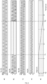
- FIG. 4 represents an example of currents and voltages flowing through the power supply circuit 100 during its operation.
- Graph a) represents the voltage Ve of the first alternating electrical network 110.
- Graph b) represents the current circulating in the first terminals B1 of the uninterrupted power supply circuit 100.
- Graph c) represents the voltage Vs delivered to the second alternating electrical network 120.
- Graph d) represents the current I S circulating in the second terminals B2 of the circuit uninterruptible power supply 100.
- Graph e) represents the voltage Vbat of the direct voltage source 130.
- the first alternating electrical network 110 is connected to the uninterrupted power supply circuit 100 and delivers an alternating voltage Ve to it.
- the voltage Ve delivered by the first alternating electrical network 110 is characterized for example by a peak voltage of 325 V or an effective voltage of 230V for a frequency of 50Hz.
- the input current le is regulated so as to be in phase with the voltage Ve delivered by the first alternating electrical network 110 and to allow a substantially constant voltage Vbat, for example approximately 198V, across the direct voltage source 130.
- a voltage Vs delivered to the second alternating electrical network 120 is for example regulated at a peak voltage of 325 V or an effective voltage of 230V for a frequency of 60Hz.
- a sinusoidal current Is in phase with the voltage Vs circulates in the second terminals B2 of the uninterruptible power supply circuit 100, because in this example the load connected to the second terminals B2 is a resistance. But the current Is could be out of phase with the voltage Vs, particularly if the load was inductive or capacitive.
- the first alternating electrical network 100 is disconnected from the uninterrupted power supply circuit 100.
- the voltage VS across the direct voltage source 130 decreases because it then supplies the second alternating electrical network 120. It can be seen that the voltage Vs and the current Is are not impacted by this disconnection and are maintained thanks to the emergency power supplied by the direct voltage source 130.
- the first alternating electrical network 110 is reconnected to the uninterrupted power supply circuit 100.
- the voltage Vs and the current Is maintain their shape.
- the voltage Vbat across the direct voltage source 130 gradually increases, thanks to the energy supplied by the first alternating electrical network 110.
- the speed of charging the direct voltage source 130 can be more or less rapid depending on the power devoted to charging by the uninterruptible power supply circuit.
- the uninterrupted power supply circuit 100 therefore correctly performs its backup power function for the second alternating electrical network 120, while allowing charging of the direct voltage source 130 when the first alternating electrical network 110 is operational.
- the uninterruptible power supply circuit 100 allows energy exchanges in all directions.
- the direct voltage source 130 or the second alternating electrical network 120 can send energy to the first alternating electrical network 110.
- the second alternative electrical network 120 can provide energy when it contains energy production means, for example decentralized renewable energy production means.
- the energy exchanges mentioned above between the first alternating electrical network 110 and the direct voltage source 130 and/or between the direct voltage source 130 and the second alternating electrical network 130 can thus be negative.
- the uninterruptible power supply circuit according to the invention can thus be used for network storage, that is to say the storage and restitution of energy between the first alternating network 110 and the direct voltage source 130, while by providing quality and uninterrupted alternating voltage to the second alternating electrical network 120.
- the uninterrupted power supply circuit operates 100 so as to ensure uninterrupted power supply to the second alternating electrical network 120.
- Energy is taken from the first alternating electrical network 110 to ensure the charging the direct voltage source 130, for example by regulation based on a set voltage, and to ensure the needs of the second alternating electrical network 120.
- the first network 110 then provides the accumulation of power necessary for charging the direct voltage source 130 and the power necessary for the second network 120 (through the direct voltage source).
- the energy destocking phase corresponds to an injection, into the first alternating electrical network 110, of part of the energy stored in the energy source. direct voltage 130.
- the uninterrupted power supply circuit 100 then behaves as a producer of electrical energy with respect to the first alternating electrical network 110. This may be desired, for example, to carry out storage/removal arbitrations depending on variations in the price of electricity, or as a support service for the supply-demand balance of electricity on the first alternative electricity network 110.
- This service can for example be a frequency regulation assistance service on the first alternative electrical network 110.
- Such a regulation assistance service includes in particular the injection thereon of an electrical power which is a function of the deviation of the frequency of the first alternative electrical network 110 relative to its reference frequency, especially below it.
- the reference frequency is 50Hz.
- the power to be injected into the first alternating electrical network 110 can be known. This power is in particular released from the direct voltage source 130 which thus provides both the power injected into the first alternating electrical network 110 as well as the power necessary for the second alternating electrical network 120.
- the uninterrupted power supply circuit 100 may comprise a control unit 180 represented schematically in Figure 5 .
- This control unit 180 is similar to the control unit 170 illustrated in Figure 3 , except that the first control block 1 includes a sub-control block 1'.
- the control sub-block 1' makes it possible to select either a first power determined as a function of the difference between a set voltage and an instantaneous voltage at the third terminals B3 of circuit 100, or a second power Pinj to be injected into the first electrical network alternative 110.
- the sub-block 1' may comprise a selection unit MUX which selectively connects the circuit delivering the first power or the circuit delivering the second power.
- An activation circuit 16' can be used to activate the sub-block 1' when the DC voltage source 130 must be used for energy removal by the uninterruptible power supply circuit 100.
- the control sub-block 1' then delivers the selected power to the following control blocks, as the setpoint power.
- the other control blocks work as described previously.
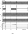
- FIG. 6 represents an example of currents and voltages flowing through the power supply circuit 100 during such storage and retrieval operation with respect to the first electrical network 110, while ensuring uninterrupted power supply to the second electrical network 120.
- Graph a) represents the voltage Ve of the first alternating electrical network 110.
- Graph b) represents the current circulating in the first terminals B1 of the uninterrupted power supply circuit 100.
- Graph c) represents the voltage Vs delivered to the second network alternating electric current 120.
- Graph d) represents the current I S circulating in the second terminals B2 of the uninterrupted power supply circuit 100.
- Graph e) represents the input power Pe, that is to say the power exchanged with the first alternative electrical network 110.
- the circuit without power supply 100 operates in a manner similar to the operation illustrated in Figure 4 .
- the power supply circuit 100 operates so that the first electrical network 110 supplies both the direct voltage source 130 - by charging it if necessary - and the second electrical network 120.
- the input power Pe is positive.
- the circuit without power supply 100 switches to autonomous operation in which the second electrical network 120 is powered only by the direct voltage source.
- the input power Pe is then zero, since the first electrical network 110 is disconnected.
- the first electrical network 110 becomes available again, and begins to power the second electrical network 120 again, as well as recharging the direct voltage source 130 which was partially discharged during the autonomous operation phase.
- the input power Pe is greater than that over the period T0-T1, due to the fact that the direct voltage source 130 has been partly discharged and therefore requires recharging.
- the circuit without power supply 100 switches to a mode in which it injects electrical power into the first electrical network 110.
- the input power becomes negative and is for example regulated at -100W .
- the target power delivered by the first control block is -100W.
- an electrical power of 100W is injected into the first network, coming from the direct voltage source 130; while the second electrical network 120 continues to be supplied without interruption also from the direct voltage source 130.
- This injection of power onto the first electrical network 110 is typically carried out by an injection of a current I on the first electrical network 110 in phase opposition with the voltage Ve of the first electrical network 110.
- the injected power value of 100W is purely illustrative. Other values are possible depending on the need of the first electrical network 110 and the storage capacities of the direct voltage source 130 and/or the second electrical network 120.
- the second electrical network 120 is correctly supplied without interruption during all successive phases of operation. This shows the proper functioning of the uninterrupted power supply circuit 100, particularly in a context of network storage/retrieval or other services to the first network 110 requiring the injection of electricity available from the direct voltage source 130 or the second electrical network 120.
- the first control block 1 can be configured to determine a set power to be delivered to the third terminals B3 of the uninterrupted power supply circuit 100 in function of a difference between a set voltage V bat0 and an instantaneous voltage V bat at the third terminals B3 of the uninterruptible power supply circuit 100, as for example illustrated in figures 3 And 5 .
- the first control block can also be configured to determine the setpoint power as a function of a power Pinj to be delivered to the first terminals B1 of the uninterruptible power supply circuit 100, as for example illustrated in figure 5 .
Landscapes
- Engineering & Computer Science (AREA)
- Power Engineering (AREA)
- Business, Economics & Management (AREA)
- Emergency Management (AREA)
- Stand-By Power Supply Arrangements (AREA)
- Inverter Devices (AREA)
Applications Claiming Priority (1)
| Application Number | Priority Date | Filing Date | Title |
|---|---|---|---|
| FR2214316A FR3144436B1 (fr) | 2022-12-22 | 2022-12-22 | Circuit d’alimentation sans interruption |
Publications (1)
| Publication Number | Publication Date |
|---|---|
| EP4391297A1 true EP4391297A1 (de) | 2024-06-26 |
Family
ID=85792208
Family Applications (1)
| Application Number | Title | Priority Date | Filing Date |
|---|---|---|---|
| EP23213207.6A Pending EP4391297A1 (de) | 2022-12-22 | 2023-11-30 | Unterbrechungsfreie stromversorgung |
Country Status (3)
| Country | Link |
|---|---|
| US (1) | US12506355B2 (de) |
| EP (1) | EP4391297A1 (de) |
| FR (1) | FR3144436B1 (de) |
Citations (1)
| Publication number | Priority date | Publication date | Assignee | Title |
|---|---|---|---|---|
| US20190386509A1 (en) * | 2018-06-19 | 2019-12-19 | Delta Electronics, Inc. | Power supply circuit and ups auxiliary power supply system having the same |
Family Cites Families (3)
| Publication number | Priority date | Publication date | Assignee | Title |
|---|---|---|---|---|
| JP3825020B2 (ja) * | 2002-08-01 | 2006-09-20 | 株式会社アイ・ヒッツ研究所 | 分散給電システム |
| US9263968B2 (en) * | 2011-06-22 | 2016-02-16 | Eetrex, Inc. | Bidirectional inverter-charger |
| JP7186381B2 (ja) * | 2019-09-18 | 2022-12-09 | パナソニックIpマネジメント株式会社 | 電力変換装置 |
-
2022
- 2022-12-22 FR FR2214316A patent/FR3144436B1/fr active Active
-
2023
- 2023-11-30 EP EP23213207.6A patent/EP4391297A1/de active Pending
- 2023-12-04 US US18/528,676 patent/US12506355B2/en active Active
Patent Citations (1)
| Publication number | Priority date | Publication date | Assignee | Title |
|---|---|---|---|---|
| US20190386509A1 (en) * | 2018-06-19 | 2019-12-19 | Delta Electronics, Inc. | Power supply circuit and ups auxiliary power supply system having the same |
Also Published As
| Publication number | Publication date |
|---|---|
| FR3144436B1 (fr) | 2025-01-10 |
| FR3144436A1 (fr) | 2024-06-28 |
| US20240213798A1 (en) | 2024-06-27 |
| US12506355B2 (en) | 2025-12-23 |
Similar Documents
| Publication | Publication Date | Title |
|---|---|---|
| EP0654887B1 (de) | Unterbrechungsfreie Stromversorgung mit gemeinsamem Nullleiter und Doppelaufwärtskonverter | |
| EP3607644B1 (de) | Verfahren zur steuerung einer aufladevorrichtung an bord eines elektro- oder hybridfahrzeugs | |
| EP2532069B1 (de) | Ladungsausgleichssystem für batterien | |
| EP0749191B1 (de) | Ladegerät für elektrischen Akkumulator | |
| EP2532068B1 (de) | Ladungsausgleich für batterien | |
| EP3554887A1 (de) | Verfahren zur steuerung einer aufladevorrichtung an bord eines elektro- oder hybridfahrzeugs | |
| EP2567443A2 (de) | Ausgleichssystem für strombatterie und entsprechende lastverteilungsmethode | |
| EP2524397A2 (de) | System zur verwaltung und steuerung von pv-modulen | |
| FR3029709A1 (fr) | Dispositif d'alimentation et convertisseur de tension continue ameliore | |
| FR2987509A1 (fr) | Circuit de charge d'une installation de stockage d'energie et son procede de charge | |
| FR2906787A1 (fr) | Systeme et procede d'alimentation en courant continu d'un reseau electrique a bord d'un aeronef | |
| FR2987510A1 (fr) | Circuit de charge d'une installation d'alimentation en energie et son procede d'application | |
| EP0237369A1 (de) | Elektrisches Speisegerät mit Wechselspannungsausgang | |
| FR2987512B1 (fr) | Circuit de charge d'une installation d'alimentation en energie et son procede d'application | |
| CA3183945A1 (fr) | Procede de pilotage de charge et de decharge d'une pluralite de dispositifs de stockage d'energie electrique | |
| EP3721543A1 (de) | Gleichspannungswandler mit vorladung eines ersten stromnetzes aus einem zweiten stromnetz | |
| FR3089721A1 (fr) | Dispositif de charge réversible pour véhicule automobile | |
| FR3144436A1 (fr) | Circuit d’alimentation sans interruption | |
| FR2987524A1 (fr) | Dispositif de prise de tension continue pour une installation de stockage d'energie et procede pour generer une tension continue a partir d'une installation de stockage d'energie | |
| EP2504912A1 (de) | Dc-dc-wandler für strom mit einer gleichstromquelle | |
| FR2987511A1 (fr) | Dispositif de prise de tension continue pour une installation de stockage d'energie et procede pour generer une tension continue a partir d'une installation de stockage d'energie | |
| EP3685485A1 (de) | Verfahren zur steuerung eines ladesystems einer traktionsbatterie | |
| EP4014309B1 (de) | Induktive halteschaltung | |
| EP4465482A1 (de) | Unterbrechungsfreie stromversorgungsschaltung mit abwärts- und aufwärtswandler | |
| EP4732404A1 (de) | Verfahren zur steuerung einer vorrichtung zur übertragung elektrischer energie basierend auf induktion |
Legal Events
| Date | Code | Title | Description |
|---|---|---|---|
| PUAI | Public reference made under article 153(3) epc to a published international application that has entered the european phase |
Free format text: ORIGINAL CODE: 0009012 |
|
| STAA | Information on the status of an ep patent application or granted ep patent |
Free format text: STATUS: REQUEST FOR EXAMINATION WAS MADE |
|
| 17P | Request for examination filed |
Effective date: 20231130 |
|
| AK | Designated contracting states |
Kind code of ref document: A1 Designated state(s): AL AT BE BG CH CY CZ DE DK EE ES FI FR GB GR HR HU IE IS IT LI LT LU LV MC ME MK MT NL NO PL PT RO RS SE SI SK SM TR |
|
| RAP3 | Party data changed (applicant data changed or rights of an application transferred) |
Owner name: COMMISSARIAT A L'ENERGIE ATOMIQUE ET AUX ENERGIESALTERNATIVES |
|
| STAA | Information on the status of an ep patent application or granted ep patent |
Free format text: STATUS: EXAMINATION IS IN PROGRESS |